

Page 1
GB/DAS
Installation Instructions
Devi ex™ heating cables
™
Devi ex
for thin oor constructions,
cement oors, etc.
DTIE-10/17
www.devi.com
Page 2

Notes
Page 3

Devi ex™ DTIE-10 and DTIE 17 heating cables
Devi ex™ type DTIE is a 2-wire heating cable. The cable is CE-Marked, and
NEMKO certi ed in accordance with
IEC 60800. The cable is suitable for both
indoor and outdoor use, and may be
Areas of use
Installation Normal W/m
120
150
Bathroom oor
Living room
Porch
Hall
WC
Bedroom
Corridor
Child’s bedroom
Basement room
Laundry room
Ground heat
Kindergarten
Thin oors
O ce
Gutters,
per metre gutter
80
120
100
70
70
70
70
70
120
40
50
80
30
100
150
140
100
100
100
100
100
150
60
70
-
100
-
40
-
Max. W/m
attached directly to any mesh reinforcement.
Please consult the table below for the
correct choice of cable.
DTIE-10
200
100
200
200
200
100
200
100
100
200
100
DTIE-17
X
X
X
X
X
X
X
X
X
X
X
X
X
X
X
X
X
X
X
X
X
Cable speci cations
Cable
Type
Voltage
Output
Diameter
Cold tail
Conductor
insulation
Inner casing
Sheath
Max. temperature
Devi ex™ DTIE-10, and
DTIE-17
2-wire with screen
230 V
10 og 17 W/m
Ø 6 mm
2,5 m - 2 x 1,5 mm
with screen
Flourplast
PEX (polyethylene)
Polyole n
65ºC
Recommended areas of use – Devi ex™ DTIE-10
Surface
Standard
concrete
Thin oor
construction
Recommended areas of use – Devi ex™ DTIE-17
Vanlig støp
Standard
concrete
Bathroom
Thin oor
construction
output
50-80 W/m
80-125 W/m
Surface
output
75-200 W/m
125 -200 W/m
125-150 W/m
c-c distance
20 - 12 cm
20 - 12 cm
12 - 8 cm
c-c distance
22 - 8 cm
22 – 8 cm
15 - 8 cm
14 - 11 cm
Page 4

General Installation instructions
The following guidelines must be
observed when installing the heating
cable:
The heating cable must be
1.
installed with a xed connection
(not a plug socket).
An authorized electrician must con-
2.
nect the heating cable to the thermostat.
The speci ed maximum output for
3.
various installation and operating
conditions must be respected.
The heating cable must be
4.
protected against mechanical
stress at all times and must never
be stretched.
Clean the surface and remove any
5.
sharp objects.
The ex diameter of the cable
6.
must not be less than 6 x the cable
diameter.
Ensure that the cable do not touch
7.
or cross one another.
Do not lay the connection box and
8.
the end of the heating cable in wet
areas such as showers or under bathtubs, etc.
9.
Do not lay the heating cable under
built-in baths, cupboards, walls, etc.
10.
Connect the earth wire of the
heating cable in accordance with
regulations.
11.
Do not shorten the heating cable
as this will increase the output per
metre cable.
12.
Check the insulation resistance and
the resistance of the heating cable
once it has been installed, both
before and after the concrete is
poured. The resistance of the cable
must be as speci ed on the label: -5
– +10%.
13.
It should still be possible to move
the heating cable after attaching any
type of xing strips.
14.
The heating cable must be equipped
with a circuit breaker. In addition, we
recommend the use of a Devireg™
thermostat.
15.
The cable is marked every
one-meter but please note that
smaller deviations compared to the
cable’s actual length might occur.
The meter marking is only meant as
a help when laying out the cable.
Fig. 1
The heating cable should not be installed at temperatures below –7°C. If you have
to lay the cable at low temperatures, try connecting the cable for a short while as this
will make it easier to install. Please note that the cable must, in this case, be rolled out
to keep the cable temperature from getting too high.
Page 5

Installing the cable in thin oor constructions
Thin oor constructions are particularly
relevant in connection with house renovations and in places where construction
height and drying times, etc. must be
taken into account.
Please note that, in case of thin oor
constructions, it is important to choose
the right cable for the oor in question.
The C-C distance must not exceed 12 cm.
DEVI o ers the complete heating solution.
Thin oor construction on concrete
with ceramic tiles
Fig. 2
Any instructions relating to the concrete
mixture must be closely observed, and
the supplier of the oor covering must
be informed that under oor heating has
been installed in order to ensure that the
most suitable product is chosen.
When installing a wood/laminate oor,
we recommend the use of a combination thermostat that limits the oor
temperature, such as the Devireg™ 132,
522, 535.
Tiles
Damp proof membrane in all
wet rooms
Concrete
Sensor
™
Devi ex
heating cable
™
Devifast
xing strips
Existing oor
Thin oor construction on wooden
oor
Fig. 3
Local building regulations for wet rooms must be
observed. In wet rooms, the membrane should be
applied to the top of the concrete.
Tiles
Damp proof membrane in all wet
rooms
Concrete
Sensor
™
Devi ex
heating cable
™
Devifast
xing strips, possibly mesh
or glued to base
Fire retardant base
Existing oor
Page 6
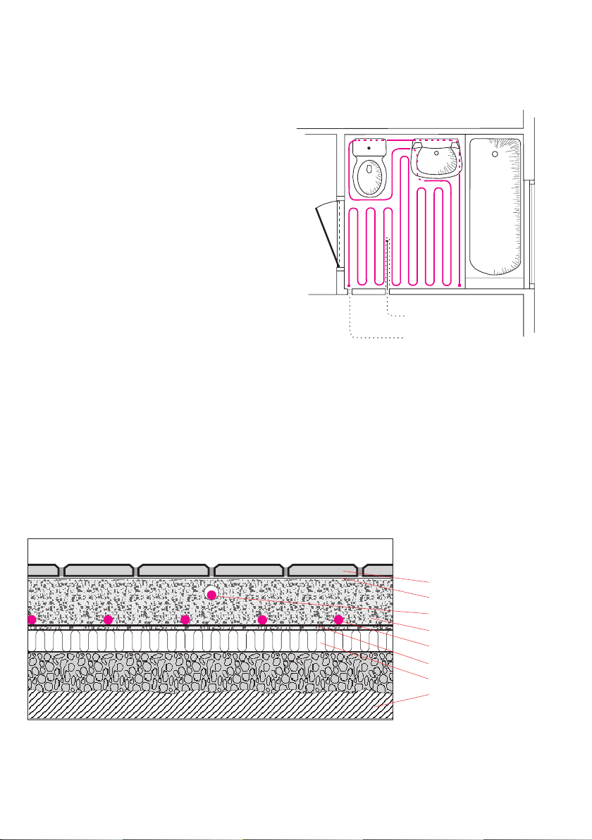
Installing the heating cable in cement oors
Lay the heating cable evenly across
the oor, avoiding any obstacles. The
surface must be clean and free from
sharp objects. For quick and simple
installation, we recommend the use of
Devifast
™
xing strips.
A Devireg™ thermostat should be used
at all times. If a oor sensor is used, it
should be installed in a pipe. The pipe
should be placed in the concrete between the cable loops and the end of the
pipe must be sealed. We recommend
that you draw a simple sketch showing
the cable’s position.
A decision must be made as to
whether or not the oor should be
insulated. This depends on the existing
oor construction, the location of the
oor, the construction height, etc. The
under oor heating must not be used
until the concrete has hardened, i.e. after
approximately 6–8 weeks or as speci ed.
Fig. 4
Thermostat sensor
Connection to heating cable
Traditional concrete
Fig. 5
*) Membrane must be applied in accordance with local building regulations.
Flooring
Membrane (optional)*
Sensor
Concrete 3-5 cm (reinforced)
™
heating cable
Devi ex
™
xing strip
Devifast
Insulation (optional)
Foundation
Page 7

Installing devi ex in market gardens and
greenhouses, etc.
To improve growing conditions for
plants the installed output must not
2
exceed 90 W/m
when using Devi ex™
cables. The heating cable should be
installed at su cient depth in order to
Fig. 6
Calculating C-C distances
Centre distances for choice of cable in accor-
dance with output per m2 for
c/c 17
5 cm
6 cm
7 cm
8 cm
9 cm
10 cm
11 cm
12 cm
13 cm
14 cm
15 cm
16 cm
17 cm
18 cm
19 cm
20 cm
DTIE-10/17
DTIE-17
340
283
243
212
189
170
154
142
131
121
113
106
100
94
89
85
10
DTIE-10
200
167
143
125
111
100
91
83
77
71
67
62
59
55
53
50
ensure that it is not damaged when the
soil is worked, i.e. at a depth of 25 cm
with a covering of netting wire, or at a
depth of 10 cm with a covering of
agstones or similar.
10-15 cm earth
Tiles
(or other protection)
2-3 cm sand
Devi ex™ heating cable
Devifast™ xing strips
2-3 cm sand
2-3 cm styropor (optional)
Earth
c-c distance
in metres =
c-c distance
in cm =
Output per metre cable
Output per m
2
open space
m2 open space x 100
Cable length
Example:
A bathroom measures 5 m2 and requires 140
2
W/m
. The choice is DTIE-17 – 700 W – 41 m.
5 x 100
= 12,2 cm c-c distance
41
Page 8

Control and adjustment
Devi ex™ heating cables must be thermostat controlled. Optimum control
will be achieved with the use of Devireg™
electronic thermostats designed to
provide rapid and e ective control
taking both comfort and economy into
consideration.
Thermostats
Devireg™ 130 series, wall-mounted
Typ e
130
131
132
Devireg™ 530 series, ush-mounted
Type Temp. range
530
531
532
Temp. range Sensor Amp Nightly reduction
5ºC - 45ºC
5ºC - 35ºC
5ºC - 35ºC
5ºC - 45ºC
5ºC - 35ºC
5ºC - 35ºC
Floor
Room
Dual
Sensor
Floor
Room
Dual
A wide range of Devireg™ thermostats is
available to meet various requirements
for individual installations.
The sensor may be extended by up to 50
m using min. 1.5 mm
10
10
10
Amp
10
10
10
2
installation cable.
5ºC
5ºC
5ºC
Nightly reduction
5ºC
5ºC
5ºC
Devireg™ 330 for DIN rails – supplied without sensor
Type Temp. range
330
330
Devireg™ 540/550 series, ush-mounted
Type Temp. range
550
5ºC - 45ºC
15ºC - 30ºC
5ºC - 45ºC
Sensor
All
All
Sensor
Dual
Sensors and other accessories
– Floor sensor at 4 and 10 metres
– Devifast™ xing strips
Amp
16/10
16/10
Amp
16
Nightly reduction
5ºC
5ºC
Nightly reduction
0-15ºC
Page 9

Notes
Page 10

Use this page to
sketch the cable’s
position.
Page 11

The DEVI Guarantee
™
You have purchased a Deviheat
which we are sure will serve to improve
the comfort and economy of your home.
Deviheat
™
provides a complete heating
solution with Devi ex™ heating cables or
Devimat™ heating mats, Devireg™ thermostats and Devifast™ xing strips.
system
DEVI shall undertake any repair free of
charge or supply the customer with a
new unit. Repairs shall be carried out
at no further cost to the customer. In
the case of faulty Devireg
™
thermostats,
DEVI reserves the right to repair the
unit free of charge and without any
unreasonable delays for the customer.
Should you, against all expectations,
experience a problem with your
Deviheat™ system, you will nd that
DEVI, whose products are manufactured in Denmark and sold throughout
the European Union, is subject to the
standard regulations pertaining to
product liability as speci ed in EU directive 85/374/CEE as well as all applicable
legislation in the individual countries on
the following conditions:
DEVI o ers a 10-year guarantee on all
Devi ex
™
heating cables and Devimat™
heating mats, and a 2-year guarantee
against material defects and production
defects in connection with any other
DEVI products.
The guarantee shall be valid only if the
GUARANTEE CERTIFICATE is completed
correctly and in accordance with the
instructions, and provided the fault is
inspected by or submitted to DEVI or an
authorised DEVI dealer.
The DEVI Guarantee shall not cover
installations that have been carried
out by non-authorised electricians,
faults which arise as a result of misuse
by other suppliers, damage caused by
third parties, incorrect installations or
consequential damage. All work will
be invoiced in full if DEVI is required
to inspect or repair faults that have
arisen as a result of any of the above.
The DEVI Guarantee shall not extend
to equipment which has not been paid
in full.
DEVI will, at all times, provide a rapid,
e ective and honest response to all
queries and reasonable demands from
our customers.
The above guarantee covers product
liability only, while purchases are subject to Danish legislation.
Please note that the GUARANTEE CERTIFICATE must be completed in English, and
that the ISO code Must be GB/DAS,
should be printed in the top left-hand
corner on the front of the Installation
Guidelines.
Page 12
GUARANTEE CERTIFICATE
The DEVI Guarantee is o ered to:
Name:
Adress:
Telephone:
Post code:
Please note!
The DEVI Guarantee shall be applicable only if the following
information has been supplied. Please refer to the back of this
certi cate for additional conditions.
Electrician:
Electrical installation carried out by:
Cable length:
Stock code: Cabelcode:
Anvendelse:
❑ Cement ❑ Pipe ❑ Earth
❑ Wooden oor ❑ Roof and gutters
Watt:
Date cable
installed:
Date of installation
Code on
coupling box:
Supplier’s stamp:
DEVI A/S
Ulvehavevej 61
7100 Vejle
Denmark
Tel.: +45 76 42 47 00
Fax: +45 76 42 47 03
Internet: www.devi.com
E-mail: info@devi.com
08090810 01.01
 Loading...