

Installation guide
Wire position sensor
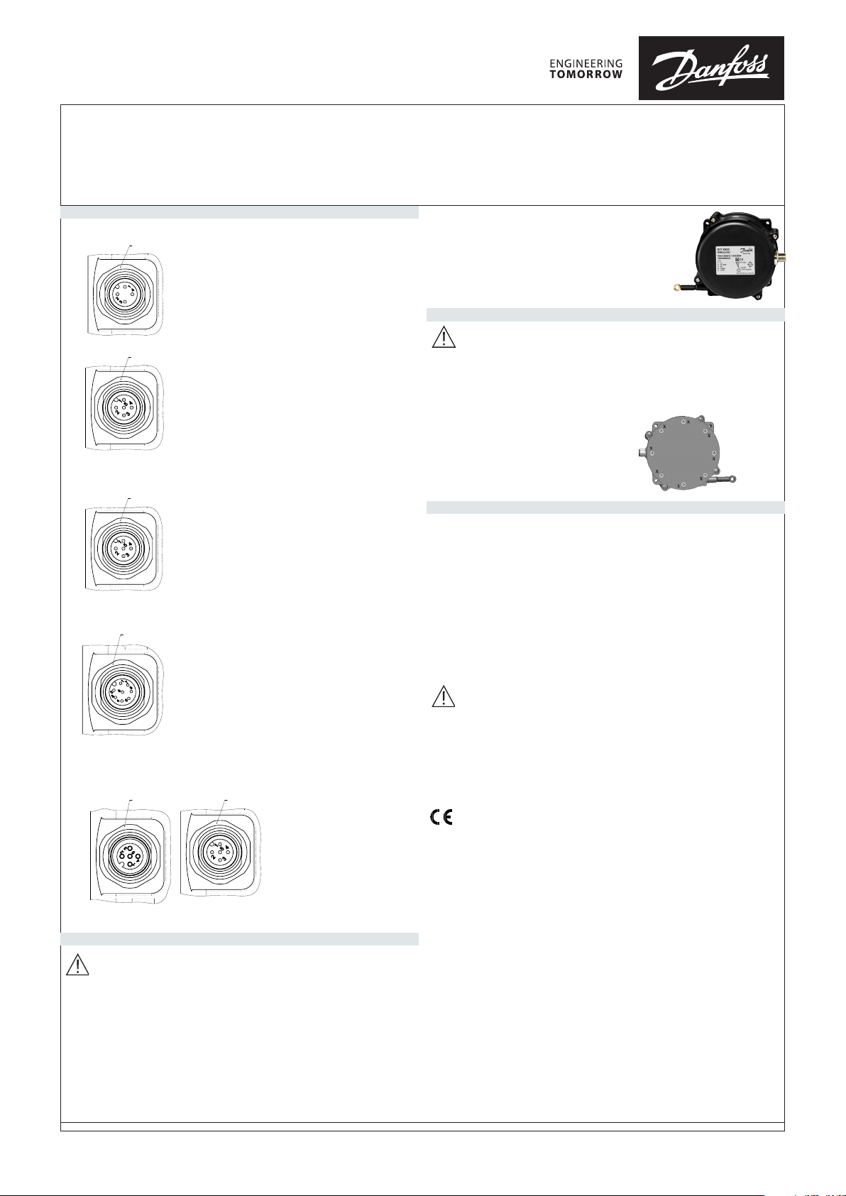
DST X800
ELECTRICAL CONNECTIONS
SINGLE VERSION
098R0004
HALF-REDUNDANT VERSION
REDUNDANT VERSION
SINGLE/REDUNDANT/HALF-REDUNDANT VERSION
M12 x 1, 4-pin
Male connector
M12 x 1, 5-pin
Male connector
M12 x 1, 5-pin
Male connector
M12 x 1, 8-pin
Male connector
M12 x 1, 8-pin
Female connector
CONNECTIONS
1. + SUPPLY
2. GROUND
3. OUTPUT
4. n.c.
CONNECTIONS
1. + SUPPLY
2. n.c.
3. GROUND
4. OUTPUT
5. n.c.
CAN CONNECTIONS
1.GROUND
2. + SUPPLY
3. GROUND
4. CAN-H
5. CAN-L
CONNECTIONS
1. + SUPPLY 1
2. GROUND 1
3. OUTPUT 1
4. n.c.
5. + SUPPLY 2
6. GROUND 2.
7. OUTPUT 2
8. n.c.
M12 x 1, 8-pin
Male connector
CAN CONNECTIONS
1. + SUUPLY
2. GROUND
3. CAN-H
4. CAN-L
CAN CONNECTIONS
1. n.c.
2. + SUPPLY
3. GROUND
4. CAN-H
5. CAN-L
CAN CONNECTIONS
1. + SUPPLY 1
2. GROUND 1
3. CAN-H 1
4. CAN-L 1
5. + SUPPLY 2
6. GROUND 2
7. CAN-H 2
8. CAN- L 2
DST X800
WIRE POSITION
SENSOR (CONTACTLESS)
Danfoss A/S 6430 Nordborg Denmark
www.danfoss.com
MOUNTING AND POSSIBLE CONFIGURATIONS
• Do not open sensor
• Do not exceed maximum operating voltage
• Do not travel over range
• Do not let snap the cable
• Do not damage/snap/crack the cable
• Special attention during mounting and operation of metal
cable and sensor
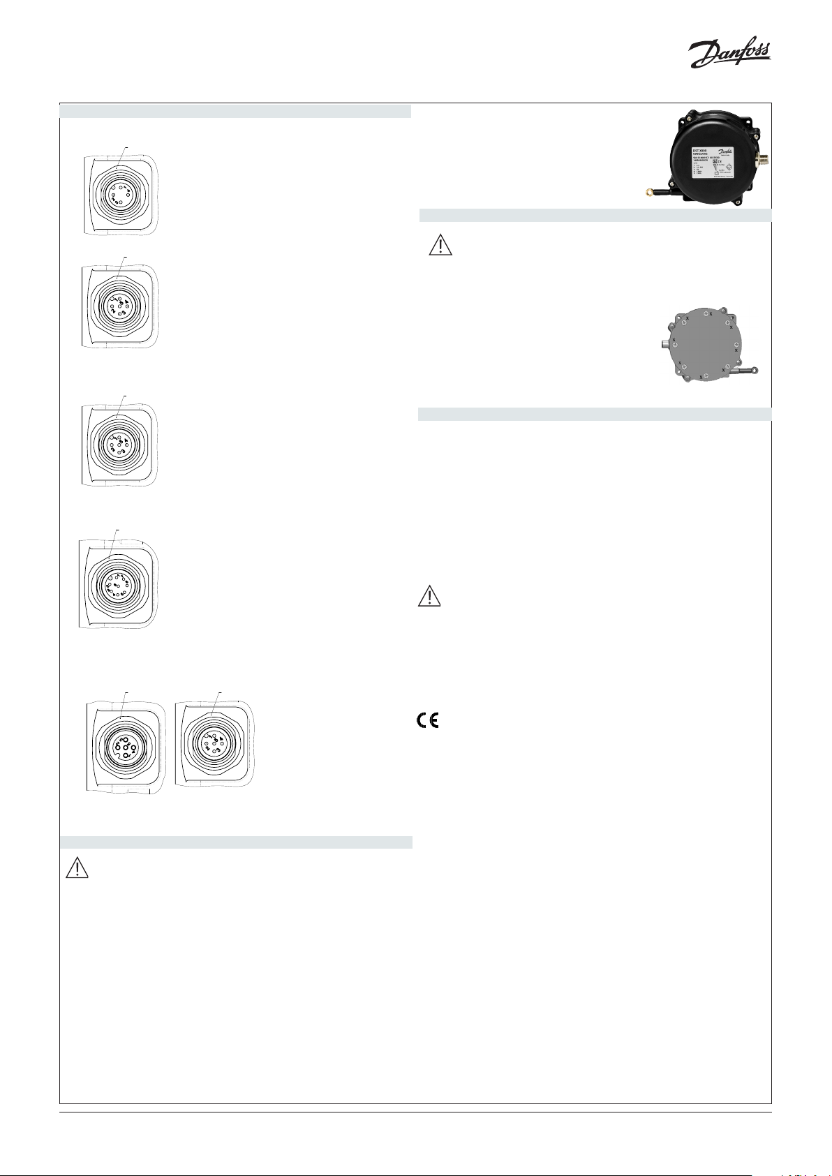
ATTENTION
For safety reasons, never screw off
the 8 screw of the rear body, shown
at the photo and marked with the X
WARNINGS AND SAFETY
Although all of the information in this manual has
been carefully checked, Danfoss A/S assumes no
liability regarding the presence of any errors or regarding
damage to property and/or harm to individuals due to any improper use
of this manual. Danfoss A/S also reserves the right to make changes to the
contents and form of this manual and to the characteristics of the devices
illustrated at any time and without prior warning.
The installation of the dev ices illustrated in the manual must be carried out by
qualified technicians in compliance with the laws and standards in force and
in agreement with the instructions contained in the manual.
LOAD CONDITIONS
+0.5Vdc…+4.5Vdc output (powered at +10..36VDC) and 0..10VDC output
(powered at +11..36VDC): apply a load resistance >100Kohm
4..20mA output (powered at < + 15..36VDC): maximum allowed load resistance is 200 ohm
4..20mA output (powered at > + 15..36VDC): maximum allowed load resistance is 500 ohm
098R0004
CAN CONNECTIONS
1. GROUND
2. + SUPPLY
3. GROUND
4. CAN-H
5. CAN-L
Danfoss A/S products with the “CE” mark are manufactured according with
the Community Directives and the related National
Legislation of concepition:
- 2011/65/EU Restriction of the use of certain hazardous substances
(RoHS)
- 2014/30/EU Electromagnetic Compatibility (EMC)
- 2001/95/EC General product safety
and that the following (parts/articles of) harmonized standards and
WARNINGS
Release of spring under tension can result in injury.
Uncontrolled cable retraction can break off cable fixing.
Broken fixing and cable can result in injury.
Cable must not be oiled or lubricated.
Do not drag cable along objects,
Cable travel should be axial to cable outlet.
Use of the transducer outside the specifications are not suitable for the unit
and can cause damages to the unit, with risk of personal injury.
regulation have been applied:
- EN 50581:2012 Technical documentation for the assessment of electri
cal and electronic products with respect to the restriction of hazardous
substances
- EN 61326-1: 2013 Electrical equipment for measurement, control
and laboratory use - EMC requirements - Part 1:
General requirements
- EN 61326-2-3: 2013 Electrical equipment for measurement, control and
laboratory use - EMC requirements - Part 2-3:
Particular requirements
Test configuration, operational conditions and perfromance creteria for
transducers with integrated or remote signal conditioning.
© Danfoss | DCS (im) | 2019.04 AN30144864079901-000101 | IC.PD.P20.FA.2Q | 1
© Danfoss | DCS (im) | 2019.04
ELEKTRISCHE ANSCHLÜSSE
EINFACHE VERSION
M12 x 1, 4-pin
Steckverbinder
M12 x 1, 5-pin
Steckverbinder
ANSCHLÜSSE
1. + SUPPLY
2. GROUND
3. OUTPUT
4. n.c.
ANSCHLÜSSE
1. + SUPPLY
2. n.c.
3. GROUND
4. OUTPUT
5. n.c.
CAN ANSCHLÜSSE
1. + SUUPLY
2. GROUND
3. CAN-H
4. CAN-L
CAN ANSCHLÜSSE
1. n.c.
2. + SUPPLY
3. GROUND
4. CAN-H
5. CAN-L
HALBREDUNDANTE VERSION
M12 x 1, 5-pin
Steckverbinder
CAN ANSCHLÜSSE
1.GROUND
2. + SUPPLY
3. GROUND
4. CAN-H
5. CAN-L
REDUNDANTE VERSION
M12 x 1, 8-pin
Steckverbinder
ANSCHLÜSSE
1. + SUPPLY 1
2. GROUND 1
3. OUTPUT 1
4. n.c.
5. + SUPPLY 2
6. GROUND 2.
7. OUTPUT 2
8. n.c.
CAN ANSCHLÜSSE1.
+ SUPPLY 1
2. GROUND 1
3. CAN-H 1
4. CAN-L 1
5. + SUPPLY 2
6. GROUND 2
7. CAN-H 2
8. CAN- L 2
EINZEL-/REDUNDANTE/HALBREDUNDANTE VERSION
M12 x 1, 8-pin
Buchse
M12 x 1, 8-pin
Steckverbincer
DST X800
SEILZUGAUFNEHMER
(BERÜHRUNGSLOS)
Danfoss A/S 6430 Nordborg Denmark
www.danfoss.com
INSTALLATION UND KONFIFURATIONEN
• Den Sensor nich öffnen
• Nicht die maximale Betriebsspannung überschreiten
• Nich die vorgesehene auszugslänge des Seizugs überschreiten
• Das Seil nich lose zurückschnellen lassen
• Das Seil nich beschädigen
• Bei Einbau und betrieb des Sensors und des Metallseils muss
grösste Vorsicht geboten
ACHTUNG
Aus Sicherheitsgründen dürfen die 8 Verschlussschrauben der hinteren Gehäuseabdeckung,
die in der Abbildung mit “X” gekennzeichnet sind,
keinesfalls entfernt werden.
WARN- UND SICHERHEITSHINWEISSE
Obgleich alle in diesem Dokument enthaltenen Informationen sorgfältig
geprüft wurden, übernimmt Danfoss A/S keinerlei Gewähr für die
Fehlerfreiheit. Sie haftet auch nicht für Sach- oder Personenschäden
aufgrund des zweckwidrigen Gebrauchs dieser Anleitung. Danfoss A/S behält
sich das Recht vor, jederzeit und ohne Ankündigung Änderungen an Inhalt
und Form dieses Dokuments sowie an den Eigenschaften der beschriebenen
Geräte vorzunehmen. Das in dieser Anleitung beschriebene Gerät darf nur
von ausgebildeten Fachkräften in Einklang mit den geltenden Gesetzen
und Bestimmungen und den in dieser Anleitung enthaltenen Anweisungen
installiert werden.
LASTBEDINGUNGEN
Ausgang +0,5VDC…+4,5VDC (Versorgung +10...36VDC) und Ausgang
0...10VDC (Versorgung
+11...36VDC): empfohlener Lastwiderstand > 100 kOhm
Ausgang +4...20 mA mit Versorgung < + 15..36VDC: max. zulässiger
Lastwiderstand 200 Ohm
Ausgang +4...20 mA mit Versorgung > + 15..36VDC: max. zulässiger
Lastwiderstand 500 Ohm
CAN ANSCHLÜSSE1.
GROUND
2. + SUPPLY
3. GROUND
4. CAN-H
5. CAN-L
SICHERHEITSHINWEISE
Durch die innenliegende gespannte Antriebsfeder kann es zu
auch schweren Verletzungen kommen.
Durch den Peitscheneffekt kann seine Befestigung beschädigt
werden.
Durch den Riss des Seils und den Bruch der Befestigung kann
es zu Verletzungen kommen.
Das Seil weder ölen noch schmieren.
Das Seil nicht an Gegenständen entlang schleifen lassen.
Das Seil muss lotrecht zum Seilausgang geführt werden.
Eine von den Spezifikationen abweichende Verwendung kann zu
irreparablen Schäden am Sensor führen.
Die Produkte mit CE-Kennzeichnung von Danfoss A/S entsprechen den
EU-Richtlinien und den entsprechenden nationalen.
Umsetzungsbestimmungen:
- 2011/65/EU Restriction of the use of certain hazardous substances
(RoHS)
- 2014/30/EU Electromagnetic Compatibility (EMC)
- 2001/95/EC General product safety
Folgenden (Teile / Artikel) harmonisierter Normen und Vorschriften
wurden angewandt:
- EN 50581: 2012 Technische Dokumentation zur Beurteilung von
elektrischen und elektronischen Produkten in Bezug auf
die Beschränkung gefährlicher Stoffe
- EN 61326-1: 2013 Elektrische Ausrüstung für Mess-, Steuer- und
Laboranwendungen - EMV-Anforderungen - Teil 1:
Allgemeine Anforderungen
- EN 61326-2-3: 2013 Elektrische Ausrüstung für Mess-, Steuer- und
Laboranwendungen - EMV-Anforderungen - Teil 2-3:
Besondere Anforderungen
Testkonfiguration, Betriebsbedingungen und Leistungskriterien für
Messumformer mit integriertem oder Fernsignal
© Danfoss | DCS (im) | 2019.04 AN30144864079901-000101 | IC.PD.P20.FA.2Q | 2

CONNEXIONS ELECTRIQUES
VERSION SIMPLE
M12 x 1, 4-pin
Connecteur mâle
CONNEXIONS
1. + SUPPLY
2. GROUND
3. OUTPUT
4. n.c.
M12 x 1, 5-pin
Connecteur mâle
CONNEXIONS
1. + SUPPLY
2. n.c.
3. GROUND
4. OUTPUT
5. n.c.
CAN CONNEXIONS
1. + SUUPLY
2. GROUND
3. CAN-H
4. CAN-L
CAN CONNEXIONS
1. n.c.
2. + SUPPLY
3. GROUND
4. CAN-H
5. CAN-L
VERSION SEMI-REDONDANTE
M12 x 1, 5-pin
Connecteur mâle
CAN CONNEXIONS
1.GROUND
2. + SUPPLY
3. GROUND
4. CAN-H
5. CAN-L
VERSION REDONDANTE
M12 x 1, 8-pin
Connecteur mâle
CONNEXIONS
1. + SUPPLY 1
2. GROUND 1
3. OUTPUT 1
4. n.c.
5. + SUPPLY 2
6. GROUND 2.
7. OUTPUT 2
8. n.c.
CAN CONNEXIONS
1. + SUPPLY 1
2. GROUND 1
3. CAN-H 1
4. CAN-L 1
5. + SUPPLY 2
6. GROUND 2
7. CAN-H 2
8. CAN- L 2
VERSION SIMPLE/REDONDANTE/SEMI-REDONDANTE
M12 x 1, 8-pin
Connecteur femelle
M12 x 1, 8-pin
Connecteur mâle
CAN CONNEXIONS
1. GROUND
2. + SUPPLY
3. GROUND
4. CAN-H
5. CAN-L
DST X800
TRANSDUCTEUR DE POSITION A FIL
(SANS CONTACT )
Danfoss A/S 6430 Nordborg Denmark
www.danfoss.com
INSTALLATION ET CONFIGURATIONS
• Ne pas ouvrir le capteur
• Ne pas dépasser la tension de fonctionnement maximale
• Ne pas voyager au dessus de la plage
• Ne laissez pas casser le câble
• Ne pas endommager/casser/casser le câble
• Attention particulière lors du montage et du fonctionnement
du câble métallique et du capteur
ATTENTION
Pour des raisons de sécurité, ne jamais dévisser la
vis 8 de la partie arrière, illustrée sur la photo et
marquée du X
AVERTISSEMENTS ET SÉCURITÉ
Malgré tout le soin apporté à la rédaction des
informations contenues dans ce document Danfoss A/S ne
pourra être tenue pour responsable des erreurs éventuelles
ou des dommages au x personnes ou aux biens dus à une utilisatio n impropre
de ce manuel. Danfoss A/S se réserve en outre d’apporter, à tout moment et
sans préavis, toute modification au contenu et à la forme de ce manuel ainsi
qu’aux caractéristiques des dispositifs illustrés. L’installation du dispositif
illustré dans ce guide doit être effectuée par des tech-niciens agréés dans le
respect de la législation et des réglementations en vigueur et en accord avec
les instructions imparties dans ce manuel.
CONDITIONS DE CHARGE
Sorties +0.5Vdc...+4.5 Vdc avec alimentation +10...36Vdc et +0..10Vdc avec
alimentation +11..36Vdc: il est recommandé une résistance de charge > 100
KΩ
Sorties +4...20mA avec alimentation < + 15..36Vcc: la résistance de charge
maximum admissible est de 200Ω
Sorties +4...20mA avec alimentation > + 15..36Vcc: la résistance de charge
maximum admissible est de 500Ω
Les produits Gefran affichant le marquage “CE” sont conformes aux
Directives européennes et à leurs lois nationales de
SÉCURITÉ
Le relâchement du ressort peut provoquer de graves
dommages corporels
Toute rétroaction non maîtrisée du câble peut provoquer la
rupture de sa fixation
La rupture du câble et de sa fixation peut provoquer des
dommages corporels
Ne jamais lubrifier le câble
Ne pas entraîner le câble le long d’objets
Le déplacement du câble doit toujours être axial par rapport à
sa sortie
Un usage autre que celui prévu par les spécifications peut endommager
irrémédiablement le capteur
transposition respectives:
- 2011/65/EU Restriction of the use of certain hazardous substances (RoHS)
- 2014/30/EU Electromagnetic Compatibility (EMC)
- 2001/95/EC General product safety
et que les (parties/articles) suivants des règlementations et normes
harmonisées ont été appliqués :
- EN 50581:2012 Technical documentation for the assessment of electrical
and electronic products with respect to the
restriction of hazardous substances
- EN 61326-1: 2013 Electrical equipment for measurement, control and
laboratory use - EMC requirements - Part 1:
General requirements
- EN 61326-2-3: 2013 Electrical equipment for measurement, control and
laboratory use - EMC requirements - Part 2-3:
Particular requirements
Test configuration, operational conditions and performance criteria for
transducers with integrated or remote signal
conditioning
© Danfoss | DCS (im) | 2019.04 AN30144864079901-000101 | IC.PD.P20.FA.2Q | 3

CONNESSIONI ELETTRICHE
VERSIONE SINGOLA
M12 x 1, 4-pin
Connettore maschio
CONNESSIONI
1. + SUPPLY
2. GROUND
3. OUTPUT
4. n.c.
M12 x 1, 5-pin
Connettore maschio
CONNESSIONI
1. + SUPPLY
2. n.c.
3. GROUND
4. OUTPUT
5. n.c.
CAN CONNESSIONI
1. + SUUPLY
2. GROUND
3. CAN-H
4. CAN-L
CAN CONNESSIONI
1. n.c.
2. + SUPPLY
3. GROUND
4. CAN-H
5. CAN-L
VERSIONE SEM-RIDONDANTE
M12 x 1, 5-pin
Connettore maschio
CAN CONNESSIONI
1.GROUND
2. + SUPPLY
3. GROUND
4. CAN-H
5. CAN-L
VERSIONE RIDONDANTE
M12 x 1, 8-pin
Connettore maschio
CONNESSIONI
1. + SUPPLY 1
2. GROUND 1
3. OUTPUT 1
4. n.c.
5. + SUPPLY 2
6. GROUND 2.
7. OUTPUT 2
8. n.c.
CAN CONNESSIONI
1. + SUPPLY 1
2. GROUND 1
3. CAN-H 1
4. CAN-L 1
5. + SUPPLY 2
6. GROUND 2
7. CAN-H 2
8. CAN- L 2
VERSIONE SINGOLE/RIDONDANTE/SEMI-RIDONDANTE
M12 x 1, 8-pin
Connettore femmina
M12 x 1, 8-pin
Connettore maschio
DST X800
TRASDUTTORE DI POSIZIONE A
FILO (SENZA CONTATTO)
Danfoss A/S 6430 Nordborg Denmark
www.danfoss.com
MOUNTING AND POSSIBLE CONFIGURATIONS
• Non aprire il sensore
• Non eccedere il massimo voltaggio operativo
• Non utilizzare il sensore in extracorsa
• Non rilasciare bruscamente il cavo
• Non danneggiare/strappare/rompere il cavo
• Prestare attenzione durante il montaggio ed il funzionamento
del sensore e del cavo metallico
ATTENZIONE
Per ragioni di sicurezza, non svitare
mai le 8 viti di chiusura del corpo
posteriore evidenziate nel disegno
con la X
AVVERTENZE e SICUREZZA
Sebbene tutte le informazioni contenute all’interno
di questo documento siano state attentamente verificate,
Danfoss A/S non si assume alcuna responsabilità circa la
possibile presenza di errori, o al danneggiamento di cose o persone dovuto a
un utilizzo improprio di tale manuale.
Danfoss A/S si riserva inoltre il diritto di apportare modifiche al contenuto e
alla forma di questo documento, come pure alle
caratteristiche dei dispositivi illustrati, in qualsiasi momento e senza alcun
avviso.
L’installazione del dispositivo illustrato nella guida deve essere effettuata da
tecnici abilitati, seguendo le leggi e normative in vigore e in
accordo con le istruzioni contenute nel presente manuale. Il sistema va usato
esclusivamente in accordo al grado di protezione previsto.
Il sensore deve essere utilizzato in accordo con le caratteristiche ambientale e
alle prestazioni dello strumento.
CONDIONI DI CARICO
CAN CONNESSIONI
1. GROUND
2. + SUPPLY
3. GROUND
4. CAN-H
5. CAN-L
SICUREZZA
Il rilascio della molla in tensione può provocare gravi lesioni
Una incontrollata retroazione del cavo può romperne il
fissaggio
La rottura sia del cavo che del fissaggio può provocare lesioni
Il cavo non deve essere oliato o lubrificato
Non trascinare il cavo lungo oggetti
La movimentazione del cavo deve essere assiale rispetto
all’uscita del cavo
Un uso differente dalle specifiche può portare ad un irreparabile
danneggiamento del sensore
Uscita +0.5Vdc…+4.5Vdc (alimentata +10..36Vdc) e uscita 0..10Vdc
(alimentata +11..36Vdc): si raccomanda una resistenza di carico >100Kohm
Uscita 4..20mA con alimentazione < + 15..36Vdc: la resistenza di carico
massima ammissibile è 200 ohm
Uscita 4..20mA con alimentazione > + 15..36Vdc: la resistenza di carico
massima ammissibile è 500 ohm
I prodotti Danfoss A/S riportanti la marcatura “CE” sono in accordo con le
Direttive Comunitarie e con la relativa legislazione
nazionale di recepimento:
- 2011/65/EU Restriction of the use of certain hazardous substances (RoHS)
- 2014/30/EU Electromagnetic Compatibility (EMC)
- 2001/95/EC General product safety
e che sono state applicate le seguenti (parti/articoli di) norme
armonizzate:
- EN 50581: 2012 Documentazione tecnica per la valutazione di prodotti
elettrici ed elettronici rispetto al Restrizioni per sostanze pericolose
- EN 61326-1: 2013 Apparecchiature elettriche per la misurazione, il
controllo e l’uso in laboratorio - Requisiti EMC - Parte 1:
Requisiti generali
- EN 61326-2-3: 2013 Apparecchiature elettriche per misurazione,
controllo e uso in laboratorio - Requisiti EMC - Parte 2-3:
Requisiti particolari
Test di configurazione, condizioni operative e criteri di prestazione per
trasduttori con segnale integrato o remoto
condizionat
© Danfoss | DCS (im) | 2019.04 AN30144864079901-000101 | IC.PD.P20.FA.2Q | 4
 Loading...