


Data Sheet
Inclination position sensor
Type DST X710
For mobile hydraulic applications
The Danfoss DST X710 entry level Inclination
sensors are developed to ensure a robust and
high-performance solution for applications
such as agricultural- and construction
machines, as well as material handling
equipments. These sensors are typically used in
safety applications in order to keep the
inclination of a machine, or just a part of it, a
safety zone for working people, under control.
Danfoss DST X710 series uses contactless MEMS
technology for both single and dual axis with
measurement ranges up to 360°.
All sensors are designed for o-highway
applications and resistant to shock and
vibrations and with high electromagnetic
compatibility and comes with either analogue
or CANopen output.
Danfoss DST X710 is designed to be double
mounted with specic spacers in order to have
a full redundant space-saving version.
Features
• MEMS technology for almost innite sensor
life time
• Dual axis up to ±85°, Single axis 360° (±180°)
• Output: Analogue or CANopen
• Electrical connector: AMP Superseal 6p
282108-1 or cable
• Accuracy: < ± 0.5% FS
• Resolution; 0.01°
• IP protection level IP67 - IPX9K with female
mating connector
AI301440806781en-000501
Inclination position sensor, type DST X710
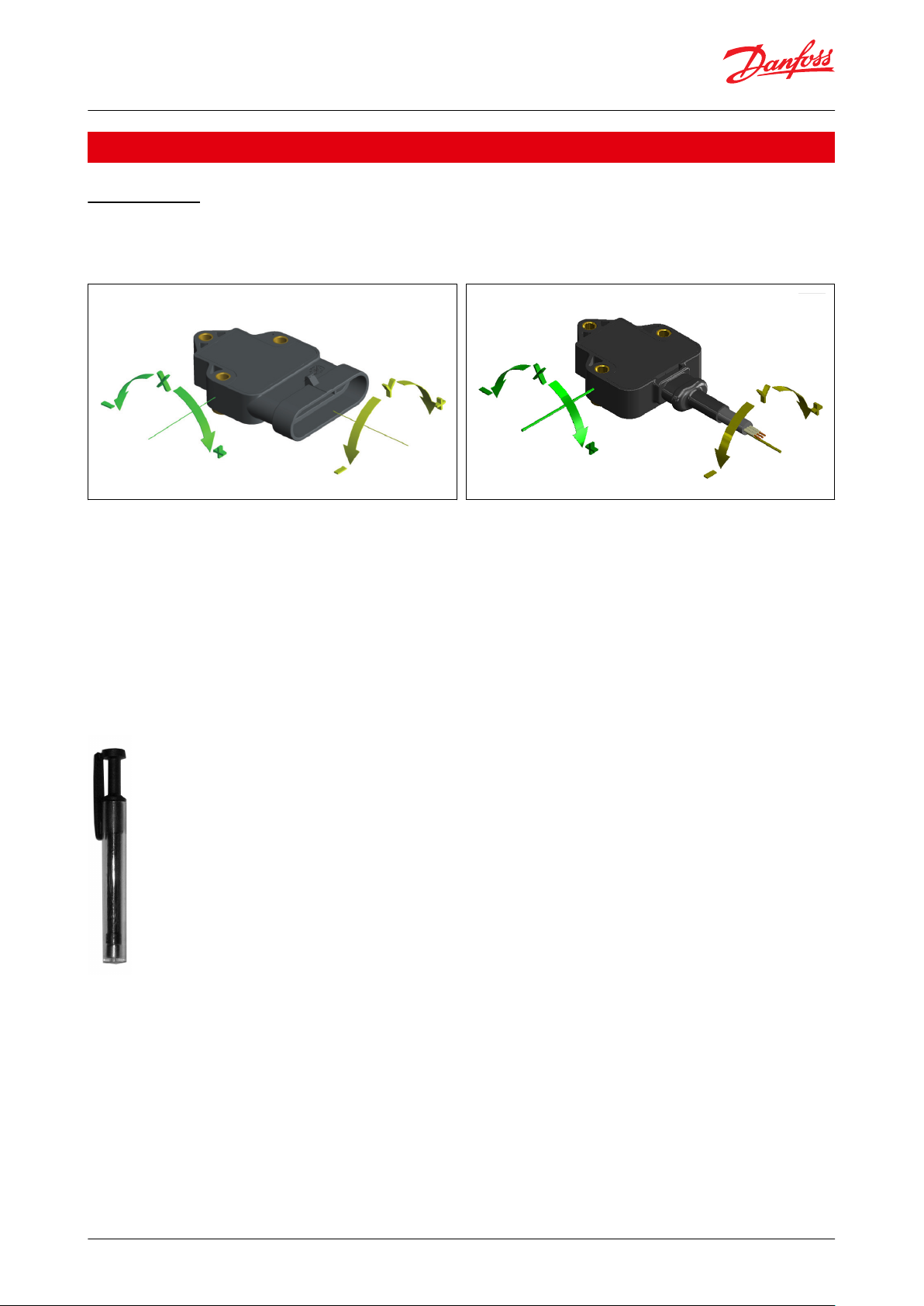
Functions
Zero function
Available for analog single circuit versions in DST X710
XY conguration (dual axis)
To activate the Autozero function make sure that:
• sensor is powered
• xing surface is free of dust or grease
• sensor is xed on the horizontal plane with suitable screws
ATTENTION:
The Autozero function can be dened within a maximum range of ±4.5° from the original zero position (factory set).
Hold the magnetic pen (accessory to order PKIT312) to the ZERO POINT indicated on the product label.
Hold the position for at least 3-5 seconds so that the operation is successful.
Figure 1: Magnetic pen
© Danfoss | Climate Solutions | 2021.02 AI301440806781en-000501 | 2

Measuring range
±10° ±15° ±20° ±30° ±45° ±60° ±85° (single axis Z / dual axis XY) 360° (±180°) single axis Z
Accuracy (Factory verication @25 °C)
< ± 0.5% FS
Temperature coecient @ 0°
Typical < ±0.006°/°K
Long term repeatability
Single axis: Typical <±0.5° in the range ±180°
Dual axis: Typical <±0.5° in the range ≤ ± 60°, ± 2° otherwise
Resolution
0.01° CANopen output; 12 bit analog output
Electrical connections
AMP Superseal 6P 282108-1, cable or cable +M12 5Pin
Output signal
CANopen, Ratiometric 10-90% of Vs, 0.5 - 4.5 V DC, 0-10 V DC or 4-20 mA
Supply voltage
CANopen, 0.5 – 4.5 V DC, 4 – 20 mA: 10 – 36 V DC; 0–10 V DC : 11–36 V DC
Ratiometric: 10 - 90% of Vs: 5 V DC
Current consumption
Analogue: < 20 mA (no load)
CANopen: < 15 mA (no load)
MTTFd [Years]
CANopen: 496
Analogue: 554
Operating temperature range
-40 – 85 °C
EMC
Emission
EN 55011
Immunity
EN 61236-3-2
Transient on supply lines
ISO 7637-2
Bulk current injection
ISO 11452-4
Vibration stability
Sinusoidal
20 g, 10 Hz – 2,000 kHz
IEC 60068-2-6
Shock resistance
Impulsive on 3 axes
50 g, 11 ms
IEC 60068-2-27
IP rating
IP67 - IPX9K with female mating
connector
Materials
Enclosure
PBT (Polybutylene terephthalate)
Net weight
0.036 kg (without cable)
Inclination position sensor, type DST X710
Product specication
Technical data
Table 1: Performance
Table 2: Electrical specications
Table 3: Environmental conditions
Table 4: Mechanical characteristics
© Danfoss | Climate Solutions | 2021.02 AI301440806781en-000501 | 3

Dual axis tilt sensor (XY) X-axis Dual axis tilt sensor (XY) - Y-axis
-45°
CLAMP LO
W
20m
A
CLAMP LOW
12m
A
4 m
A
CLAMP HIGH
4.5 V
2.5 V
0.5 V
10 V
5 V
0 V
A3
A1
A2
Level diagnosis (A1-A3 Models )
CLAMP LO
W
20m
A
CLAMP LOW
12m
A
4 m
A
CLAMP HIGH
4.5 V
2.5 V
0.5 V
10 V
5 V
0 V
A3
A1
A2
Level diagnosis (A1-A3 Models )
0° +45° -45° 0° +45°
-180°
CLAMP LO
W
20m
A
CLAMP LOW
12m
A
4 m
A
CLAMP HIGH
4.5 V
2.5 V
0.5 V
10 V
5 V
0 V
A3
A1
A2
Level diagnosis (A1-A3 Models )
0° +180°-90° +90°
Single axis tilt sensor (±180°) - Z-axis
Inclination position sensor, type DST X710
Sensor output graph
Load conditions
0.5 - 4.5 V DC output with power + 5 V DC: It is recommended a load resistance > 10 KΩ
© Danfoss | Climate Solutions | 2021.02 AI301440806781en-000501 | 4

3x
0
-0.05
Ø 4.2
27.1
22.6 ±0.20
18.7
38.3
43.8
AMP Superseal 6p
Metal insert
Max. torque: 2.5 Nm
32 ±0.20
41
24.4
65.4
37.7
34.71
34.4
0
22 AWG wires
Metal insert
Maximum torque: 2.5 Nm
Pur sheath ø5.5
Ø 8.3
10
3348.8
1 12.9
13.9
3x Ø 4.2 -0.05
16.3
32 ±0.20
=24.4=
22.6 ±0.20
27.1
18.7
18.7
31.7
Inclination position sensor, type DST X710
Dimensions
Figure 2: AMP version
Figure 3: Cable version
© Danfoss | Climate Solutions | 2021.02 AI301440806781en-000501 | 5

12345
6123456
Black
Red
Yellow
Green
Blue
White
Black
Red
Blue
White
Figure 4: AMP version
AMP Superseal 6 pole 282108-1
connector
Mated with connector
AMP 282090-1
PIN 1
PIN 6
Single axis Dual axis
123456
Connections
Ground
± Supply
Output X (dual axis)/Z(single axis)
Output Y (dual axis)/n.c (single axis)
n.c.
n.c.
CAN Connections
Ground
± Supply
n.c.
n.c.
CAN L
CAN H
Items marked n.c. should not be connected
Figure 5: Cable version
TOP
Dual axis
Single axis
Connections
Ground
± Supply
Output X
Output Y
n.c.
n.c.
CAN Connections
Ground
± Supply
CAN L
CAN H
Inclination position sensor, type DST X710
Electrical connections
AMP full redundant version
Danfoss DST X710 tilt sensor is designed to be double mounted with specic spacers (BUS027) in order to have a full
redundant space-saving version.
Please pay attention how to install the two DST X710 sensors:
Please position them both always face up or both face down.
© Danfoss | Climate Solutions | 2021.02 AI301440806781en-000501 | 6

12345612345
6
AMP Superseal 6 pole 282108-1
connector
Mated with connector
AMP 282090-1
PIN 6 PIN 1PIN 1
TOP
Single axis Dual axis
Connections
Ground
± Supply
Output Xn.c.
Output Y
n.c.
n.c.
Items marked n.c. should not be connected
CAN Connections
Ground
± Supply
n.c.
n.c.
CAN L
CAN H
Inclination position sensor, type DST X710
Figure 6: DST X710 sensors
© Danfoss | Climate Solutions | 2021.02 AI301440806781en-000501 | 7

132451324
5
3x
0
-0.05
Ø 4.2
27.1
22.6 ±0.20
18.7
38.3
43.8
AMP Superseal 6p
Metal insert
Max. torque: 2.5 Nm
32 ±0.20
41
24.4
65.4
37.7
34.71
34.4
Face up
PUR sheath Ø 5.5
M12, 5-pin
male connector
Analog connection
+ Supply
Output X
Ground
Output Y
n.c.
CAN connection
n.c.
+ Supply
Ground
CAN L
CAN H
Inclination position sensor, type DST X710
AMP Dimensions
Figure 7: AMP Version
Cable + M12 version
Figure 8: M12 connection pin
© Danfoss | Climate Solutions | 2021.02 AI301440806781en-000501 | 8

Type
Output signal
Cogurations
Code no.
DST X710
CANopen
Single axis; ±180°; 36V
098G2500
CANopen
Dual axis; ±85°; 36V
098G2501
Electrical connections
AMP Superseal 6P connector
A
Cable (specify cabel length)
F
Axis type
Dual axis (XY axis)
O
Single axis (Z axis)
V
Measuring range
(Measuring range (indicate) ±10° ±15° ±20° ±30° ±45° ±60° ±85°
(single axis Z for analogue output-dual axis XY); 360° (±180°) for single Z axis only
xxx
Measuring range (Not available)
(Redundant option not available)
000
Supply voltage
+5Vdc (only for A1 output)
L
+10…+36Vdc
(see output signal for right supply voltage)
H
Output type
0.5 - 4.5 V DC output
(available with supply L = ratiometric output and with supply H = 0.5 - 4.5 V output)
A1
0 - 10 V DC output (powered at 11 - 36 V DC
A2
4 - 20 mA output (powered at 10 - 36 V DC)
A3
CANopen output (powered at 10 - 36 V DC)
C1
Cable
Cable without connector (always “0” in case of DST X710 A MP Superseal)
0
Cable (100 mm) + M12, 5-pin male overprinted connector
1
Certicate
No certicate attached
0
Linearity curve to be attached
L
Version
Standard
033
Accessories
No accessories
X
Magnetic pen (PKIT 312)
Y
3 x spacers for redundant version (BUS027)
A
Cable length
100 mm
01
200 mm
02
500 mm
05
1 m102 m20Other length on request
-
Inclination position sensor, type DST X710
Ordering
Table 5: Ordering type
Others on request
Ordering code - on request
© Danfoss | Climate Solutions | 2021.02 AI301440806781en-000501 | 9

A
AMP Superseal 6p
0
Dual Axis (XY axis)
045
±45°
000NAH
9 - 36 V DC
C1
CANopen
0
AMP version
0
No certicate
033
Standard
X
No accessories
00
Not dened (only cable version)
Inclination position sensor, type DST X710
Table 6: Example of ordering: DST X710-A0045000HC10 0033X00
© Danfoss | Climate Solutions | 2021.02 AI301440806781en-000501 | 10

Document name
Document type
Document topic
Approval authority
098R0009
EU Declaration
EMCD/ROHS
Danfoss
Inclination position sensor, type DST X710
Certicates, declarations, and approvals
The list contains all certicates, declarations, and approvals for this product type. Individual code number may have
some or all of these approvals, and certain local approvals may not appear on the list.
Some approvals may change over time. You can check the most current status at danfoss.com or contact your local
Danfoss representative if you have any questions.
Table 7: Declarations
Conformity
• CE
• RoHS
© Danfoss | Climate Solutions | 2021.02 AI301440806781en-000501 | 11

Online support
Danfoss oers a wide range of support along with our products, including digital product information, software,
mobile apps, and expert guidance. See the possibilities below.
The Danfoss Product Store
The Danfoss Product Store is your one-stop shop for everything product related—no matter where
you are in the world or what area of the cooling industry you work in. Get quick access to essential
information like product specs, code numbers, technical documentation, certications, accessories,
and more.
Start browsing at store.danfoss.com.
Find technical documentation
Find the technical documentation you need to get your project up and running. Get direct access to
our ocial collection of data sheets, certicates and declarations, manuals and guides, 3D models
and drawings, case stories, brochures, and much more.
Start searching now at www.danfoss.com/en/service-and-support/documentation.
Danfoss Learning
Danfoss Learning is a free online learning platform. It features courses and materials specically
designed to help engineers, installers, service technicians, and wholesalers better understand the
products, applications, industry topics, and trends that will help you do your job better.
Create your Danfoss Learning account for free at www.danfoss.com/en/service-and-support/learning.
Get local information and support
Local Danfoss websites are the main sources for help and information about our company and
products. Find product availability, get the latest regional news, or connect with a nearby expert—all
in your own language.
Find your local Danfoss website here: www.danfoss.com/en/choose-region.
Spare Parts
Get access to the Danfoss spare parts and service kit catalog right from your smartphone. The app
contains a wide range of components for air conditioning and refrigeration applications, such as
valves, strainers, pressure switches, and sensors.
Download the Spare Parts app for free at www.danfoss.com/en/service-and-support/downloads.
Danfoss can accept no responsibility for possible errors in catalogues, brochures and other printed material. Danfoss reserves the right to alter its
products without notice. This also applies to products already on order provided that such alterations can be made without subsequential
changes being necessary in specications already agreed. All trademarks in this material are property of the respective companies. Danfoss and
the Danfoss logotype are trademarks of Danfoss A/S. All rights reserved.
© Danfoss | Climate Solutions | 2021.02 AI301440806781en-000501 | 12
 Loading...