

Page 1
Data Sheet
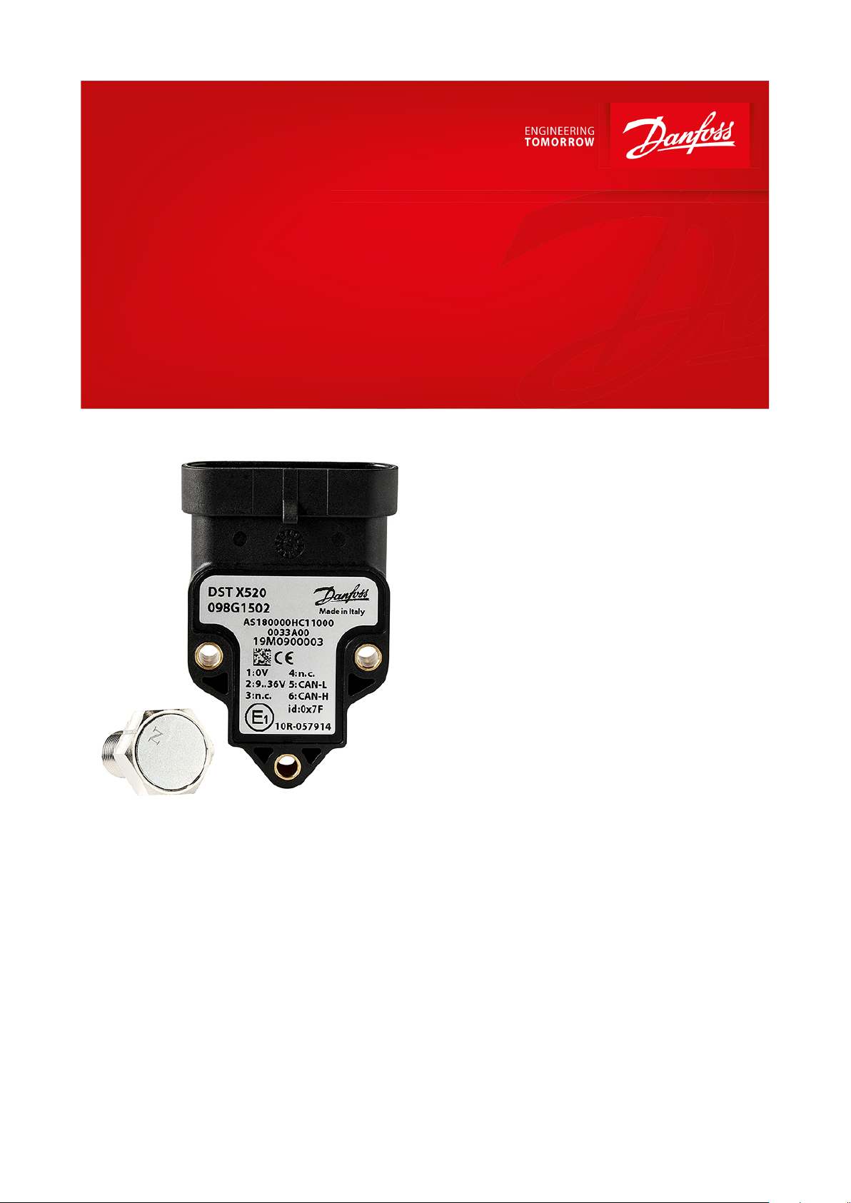
Rotary position sensor
Type DST X520
For mobile hydraulic applications
The Danfoss DST X520 rotary position sensors
without shaft are designed for use in mobile
hydraulic applications.
Danfoss DST X520 series uses contactless Hall
technology with measurement ranges up to
360°. The Sensors designed for o-highway
applications and resistant to shock and
vibrations and with high electromagnetic
compatibility.
They are E1 approved for on-highway
applications. They comes with either analogue,
CANopen or SAE J1939 output.
Single and redundant sensor types are
available, making the complete portfolio
suitable for safetycritical applications.
Features
• Contactless Hall technology for almost
innite sensor life time
• Single or Redundant ranges up to 360°
(±180°)
• Output: Analogue, CANopen or SAE J1939
• Linearity: < ± 0.5% FS
• Resolution:
◦ 12 bit (analog)
◦ 14 bit (CANopen/SAE J1939)
• IP protection level IP67 - IP69K with female
mating connector
• High quality 10 mm SmCo Magnet
AI301440445780en-000701
Page 2

Measuring range
CAN
±180° (360 °C)
Analogue
Programmable ± 15 °C
Linearity
≤ ± 0.5% FS
Resolution and speed of rotation
12 bit (analog output)
120 rpm max.
14 bit (CANopen/SAE J1939 output)
Durability
No wear through the use of permanent external magnet
Electrical connections
AMP Superseal 6p 282108, Cable or cable + M12
Output signal
CANopen / SAE J1939, Ratiometric 10-90% of Vs,
0.5–4.5 V DC, 0 –10 V DC or 4–20 mA
Supply voltage
CANopen/J1939, 0.5–4.5 V DC, 4–20 mA: 9–36 V DC
0 – 10 V DC, 11–36 V DC Ratiometric: 10-90% of Vs: 5 V DC
Current consumption
Analogue: < 10 mA / pr. channel
(no load)
CANopen/J1939: < 15 mA
(no load)
MTTFd [Years]
CANopen/J1939: 336
Analogue: 406 (Single Channel)
Operating temperature range
-40 – 85 °C
Thermal drift temperature
< 50 ppm/°C
EMC
Emission
EN 55011 and CISPR 25
Immunity
EN 61236-3-2 and ISO 11452-2
Transient on supply lines
ISO 7637-2
Bulk current injection
ISO 11452-4
Vibration stability
Sinusoidal
20 g, 10 Hz – 2,000 kHz
IEC 60068-2-6
Shock resistance
Impulsive on 3 axes
50 g, 11 ms
IEC 60068-2-27
IP protection
AMP Superseal: IP67 - IP69K
with female mating connect
Cable: IP69K
Cable + M12: IP67
Materials
Enclosure
PBT (Polybutylene terephthalate)
Net weight
0.036 kg
Rotary position sensor, type DST X520
Product specication
Technical data
Table 1: Performance
Table 2: Electrical specications
Table 3: Environmental conditions
Table 4: Mechanical characteristics
© Danfoss | Climate Solutions | 2021.02 AI301440445780en-000701 | 2
Page 3

CLAMP LOW
-
15° 0° +
15°
… [IN STEPS DI 15°] 0° …
20mA
CLAMP LOW
A
12mA4
mA
CLAMP HIGH
4.5 V
2.5 V
0.5 V
10 V
5 V
0 V
B
C
-30° 0°
-180°0°+180°
A3
A1A
2
CLAMP LOW
-
15° 0° +
15°
… [IN STEPS DI 15°] 0° …
20mA
CLAMP LOW
A
12mA4
mA
CLAMP HIGH
4.5 V
2.5 V
0.5 V
10 V
5 V
0 V
B
C
-30° 0°
+30
°
-180°0°+180°
A
3
A1A
2
CLAMP LOW
20mA
CLAMP LOW
Output 1 - Output 2
Both times CW
A
12
mA
4
mA
CLAMP HIGH
4.5 V
2.5
V
0.5 V
10 V
5 V
0 V
B
C
-180°0°+180°
A3
A
1
A
2
CLAMP LOW
20mA
CLAMP LOW
A
12
mA
4
mA
CLAMP HIGH
4.5 V
2.5 V
0.5 V
10 V
5
V
0 V
B
C
-180°0°+180°
A3
A
1
A
2
CLAMP LOW
20mA
CLAMP LOW
12
mA
4
mA
CLAMP HIGH
4.5 V
2.5 V
0.5 V
10 V
5
V
0 V
A3
A
1
A
2
CLAMP LOW
≤ ≥
20mA
CLAMP LOW
12
mA
4
mA
CLAMP HIGH
4.5 V
2.5 V
0.5 V
10 V
5 V
0
V
A3
A
1
A
2
+30°
Output 1 - CW
Clockwise CW single
Direction of rotation 1
Redundant direction of rotation 1
Redundant direction of rotation 3
Redundant direction of rotation 2
Redundant direction of rotation 4
Counterclockwise CCW single
Direction of rotation 2
Output 1 - Output 2
Both times CCW
Output 2 - CCWOutput 1 - CW Output 2 - CWOutput 1 - CCW
Rotary position sensor, type DST X520
Sensor output graph
Load conditions
+0.5 V DC – 4.5 V DC output with power 9 – 36 V DC and +0 – 10 V DC output with power 11 – 36 V DC: it is
recommended a load resistance > 100 KΩ
+0.5 V DC – 4.5 V DC output with power +5 V DC: it is recommended a load resistance > 10 KΩ
© Danfoss | Climate Solutions | 2021.02 AI301440445780en-000701 | 3
Page 4
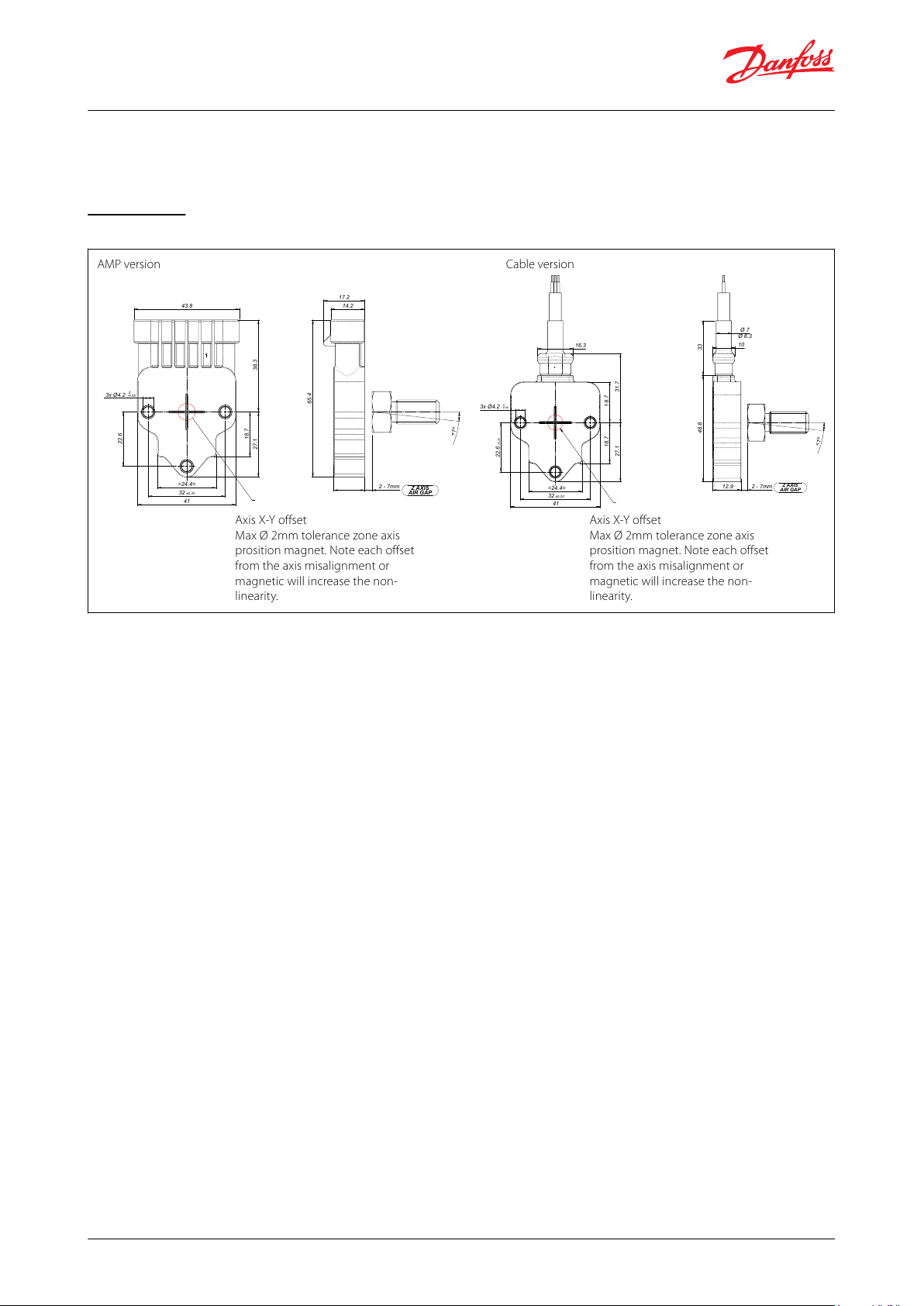
AMP version
Cable version
41
32±0.20
=24.4=
22.6
±0.20
27.1
18.7 18.7
31.7
16.3
3x Ø4.2
-0.05
0
-0.05
0
Ø 8.3
Ø 7
33
10
48.8
12.9 2 - 7mm
Z AXIS
AIR GAP
<1º
Axis X-Y offset
Max Ø 2mm tolerance zone axis
prosition magnet. Note each offset
from the axis misalignment or
magnetic will increase the non-
linearity.
Axis X-Y offset
Max Ø 2mm tolerance zone axis
prosition magnet. Note each offset
from the axis misalignment or
magnetic will increase the non-
linearity.
Z AXIS
AIR GAP
2 - 7mm
<1º
65.4
17.2
14.2
41
32 ±0.20
=24.4=
27.1
18.7
38.3
3x Ø4.2
22.6
43.8
Rotary position sensor, type DST X520
+4 – 20 mA output with power 9 - 15 V DC: maximum load resistance is 200 Ω
+4 – 20 mA output with power 15 – 36 V DC: maximum load resistance is 500 Ω
Dimensions
Figure 1: AMP and Cable version
© Danfoss | Climate Solutions | 2021.02 AI301440445780en-000701 | 4
Page 5
5
±0.05
15
13
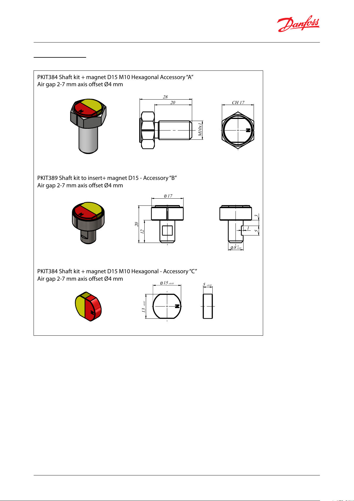
PKIT384 Shaft kit + magnet D15 M10 Hexagonal Accessory “A”
Air gap 2-7 mm axis offset Ø4 mm
PKIT389 Shaft kit to insert+ magnet D15 - Accessory “B”
Air gap 2-7 mm axis offset Ø4 mm
PKIT384 Shaft kit + magnet D15 M10 Hexagonal - Accessory “C”
Air gap 2-7 mm axis offset Ø4 mm
Ø
±0.05
±0.05
17
12
20
3
5
8
-
0
0.05
1
Ø
Ø
M10x1
20
28
CH 17
Rotary position sensor, type DST X520
Magnets models
Figure 2: Accessories
© Danfoss | Climate Solutions | 2021.02 AI301440445780en-000701 | 5
Page 6

Zero angular position of 0°
The output increases for
versions CCW
Metal insert
Max. torque: 2.5 Nm
The output increases for
versions CW
X AXIS
Y AXIS
A
C
Ref.
CW output
CWW output
A
0.5 V DC
4.5 V DC
B
Zero angular position of 0°
Zero angular position of 0°
C
4.5 V DC
0.5 V DC
Rotary position sensor, type DST X520
Electrical connections
Figure 3: AMP version, angular positions
Table 5: General data
© Danfoss | Climate Solutions | 2021.02 AI301440445780en-000701 | 6
Page 7
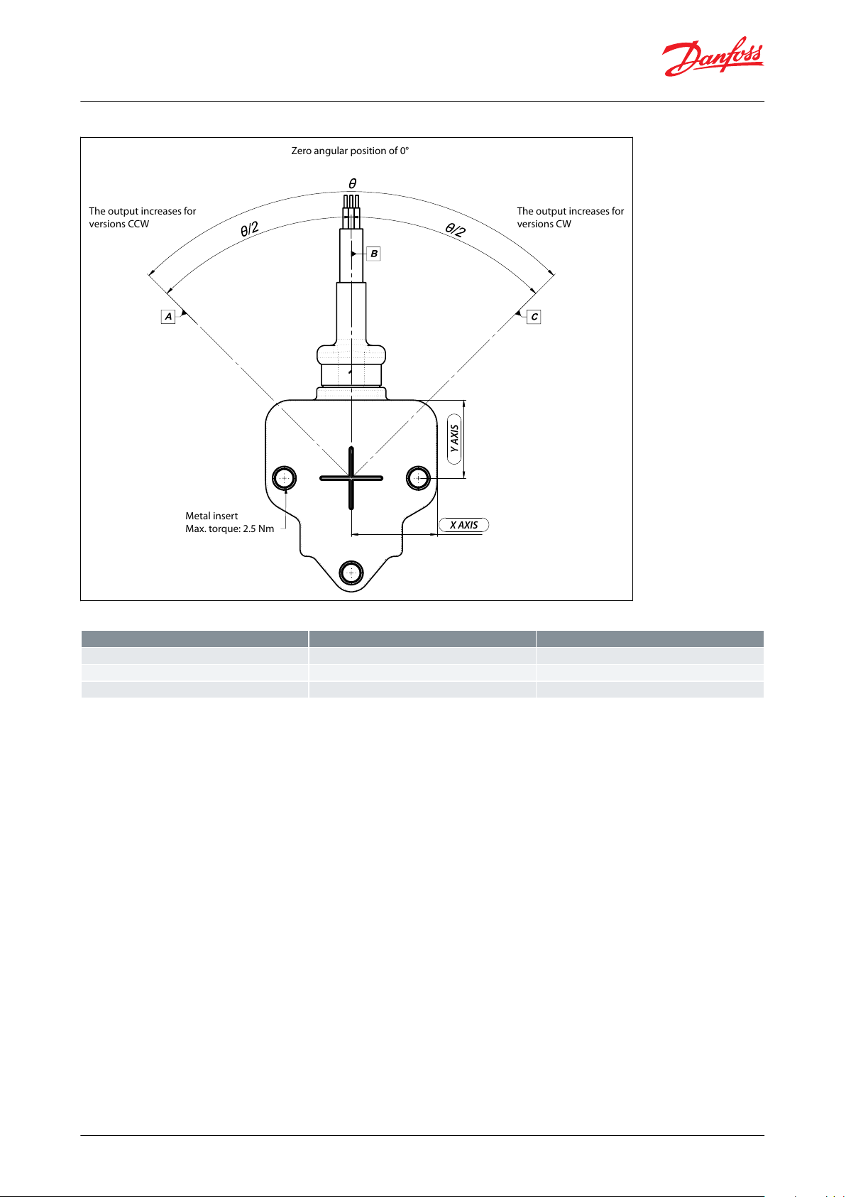
A
Zero angular position of 0°
The output increases for
versions CCW
Metal insert
Max. torque: 2.5 Nm
The output increases for
versions CW
X AXIS
Y AXIS
Ref.
CW output
CWW output
A
0.5 V DC
4.5 V DC
B
Zero angular position of 0°
Zero angular position of 0°
C
4.5 V DC
0.5 V DC
Rotary position sensor, type DST X520
Figure 4: Cable version, angular positions
Table 6: General data
© Danfoss | Climate Solutions | 2021.02 AI301440445780en-000701 | 7
Page 8
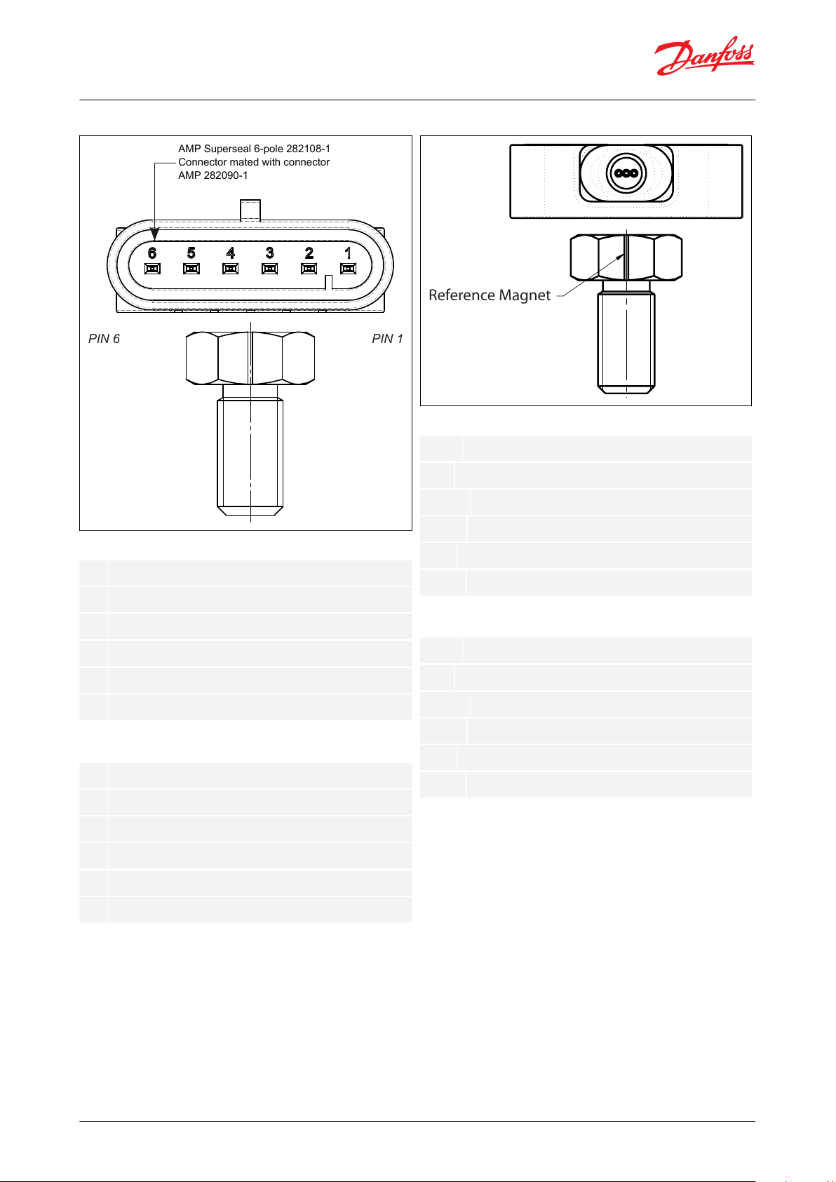
1234561
23456
PIN 6 PIN 1
AMP Superseal 6-pole 282108-1
Connector mated with connector
AMP 282090-1
Ground 1
+ Supply 1
Output 1
Ground 2
+ Supply 2
Output 2
OV (GND)
+ Vs (+9 - 36 V DC)
GND
GND
CAN-L
CAN-H
Black:
Red:
Yellow:
Green:
Blue:
White:
Black:
Red:
Yellow:
Green:
Blue:
White:
Reference Magnet
Ground 1
+ Supply 1
Output 1
Ground 2
+ Supply 2
Output 2
Ground 1
+ Supply 1
NCNCCAN-L
CAN-H
Rotary position sensor, type DST X520
Figure 5: AMP version, connections
Figure 6: Cable version, connections
Connections
Connections
Connections - CAN/J 1939
Connections - CAN/J 1939
© Danfoss | Climate Solutions | 2021.02 AI301440445780en-000701 | 8
Page 9

12345
PUR sheath Ø 4.4
(single output)
M12 5 pin
male connector
Ground 1
+ Supply 1
Output 1
NC
NC
Rotary position sensor, type DST X520
Figure 7: Cable + M12 version, connections
Connections
© Danfoss | Climate Solutions | 2021.02 AI301440445780en-000701 | 9
Page 10

Type
Output signal
Cogurations
Code no.
DST X520 incl. PKIT magnet
5 V Ratiometric
±180° Clockwise CW
098G1500
5 V Ratiometric
±180° CounterclokwiseCCW/CH2 clockwise CW
098G1501
36 V CANopen
±180° Clockwise CW
098G1502
36 V SAE J1939
±180° Clockwise CW
098G1503
Electrical connections
AMP Superseal 6P connector
A
Cable (specify cabel length)
F
Circuit type
Single Analog and half redundant CANopen/ J1939
S
Redundant Analog
R
Angle/Channel 1 (output for single channel)
(Analog output A1-A2-A3 programmable in steps of ±15°) (CAN/J 1939 = 180)
xxx
Angle/Channel 2 (redundant/half redundant)
Analog output = same as Channel 1 and (CAN/J 1939 = 000)
xxx
Supply voltage
+5Vdc (only for A1 output)
L
+9…+36Vdc (see output signal for right supply voltage)
H
Output type
+0.5…+4.5V DC output (available with supply L = ratiometric output and with supply H = 0.5...4.5V output)
A1
0...+10Vdc output (powered at +11..36V DC
A2
4...20mA output (powered at +9...36V DC)
A3
CANopen output (powered at +9...36V DC) (available in single version with +/-180° measurement range)
C1
SAE J1939 (powered at +9...36V DC) (available in single version with +/-180° measurement range)
C2
Rotation direction
Clockwise CW (single) Both clockwise CW (redundant or CAN/J1939
1
Counterclockwise CCW (single) Both counterclockwise CCW (redundant or CAN/J1939
2
CHANNEL 1 clockwise CW and CHANNEL 2 counterclockwise CCW (redundant version or CAN/J1939)
3
CHANNEL 1 counterclockwise CCW and CHANNEL 2 clockwise CW (redundant version or CAN/J1939)
4
Cable
Single cable without connector (always “0” in case of DST X520 A version)
0
Cable + M12, 5-pin male overprinted connector
1
Reserved
00
Linearity curve
No linearity curve attached
0
Linearity curve to be attached
L
Standard
033
Rotary position sensor, type DST X520
Ordering
Ordering type
Table 7: DST X520, ordering
Ordering code - on request
© Danfoss | Climate Solutions | 2021.02 AI301440445780en-000701 | 10
Page 11

Accessories
No accessories
X
Shaft kit + magnet D 15 M10 hexagonal (PKIT 384) (Standard)
A
Shaft kit to insert + magnet D 15 (PKIT 389)
B
Kit magnet Ø15 (PKIT 418)
C
Cable length
100 mm
01
200 mm
02
500 mm051 m102 m
20
Other length on request
-
A
AMP Superseal 6p
S
Half redundant CAN/J 1939
180
±180°
000
000H+9 - +36 Vdc
C1
CANopen
4
Channel 1: Counterclockwise CCW
Channel 2: Clockwise CW
0
No cable
00
Reserved
0
No linearity curve
033
Standard
A
Magnet PKIT384
00
Not dened (only cable version)
Rotary position sensor, type DST X520
Example of ordering: DST X520-AS180000HC14000 0033A00
© Danfoss | Climate Solutions | 2021.02 AI301440445780en-000701 | 11
Page 12

Document name
Document type
Document topic
Approval authority
098R0008
EU Declaration
EMCD/ROHS
Danfoss
Rotary position sensor, type DST X520
Certicates, declarations, and approvals
The list contains all certicates, declarations, and approvals for this product type. Individual code number may have
some or all of these approvals, and certain local approvals may not appear on the list.
Some approvals may change over time. You can check the most current status at danfoss.com or contact your local
Danfoss representative if you have any questions.
Table 8: Declarations
Approvals and Conformity
• CE
• RoHS
• E1 approval
© Danfoss | Climate Solutions | 2021.02 AI301440445780en-000701 | 12
Page 13

Online support
Danfoss oers a wide range of support along with our products, including digital product information, software,
mobile apps, and expert guidance. See the possibilities below.
The Danfoss Product Store
The Danfoss Product Store is your one-stop shop for everything product related—no matter where
you are in the world or what area of the cooling industry you work in. Get quick access to essential
information like product specs, code numbers, technical documentation, certications, accessories,
and more.
Start browsing at store.danfoss.com.
Find technical documentation
Find the technical documentation you need to get your project up and running. Get direct access to
our ocial collection of data sheets, certicates and declarations, manuals and guides, 3D models
and drawings, case stories, brochures, and much more.
Start searching now at www.danfoss.com/en/service-and-support/documentation.
Danfoss Learning
Danfoss Learning is a free online learning platform. It features courses and materials specically
designed to help engineers, installers, service technicians, and wholesalers better understand the
products, applications, industry topics, and trends that will help you do your job better.
Create your Danfoss Learning account for free at www.danfoss.com/en/service-and-support/learning.
Get local information and support
Local Danfoss websites are the main sources for help and information about our company and
products. Find product availability, get the latest regional news, or connect with a nearby expert—all
in your own language.
Find your local Danfoss website here: www.danfoss.com/en/choose-region.
Spare Parts
Get access to the Danfoss spare parts and service kit catalog right from your smartphone. The app
contains a wide range of components for air conditioning and refrigeration applications, such as
valves, strainers, pressure switches, and sensors.
Download the Spare Parts app for free at www.danfoss.com/en/service-and-support/downloads.
Danfoss can accept no responsibility for possible errors in catalogues, brochures and other printed material. Danfoss reserves the right to alter its
products without notice. This also applies to products already on order provided that such alterations can be made without subsequential
changes being necessary in specications already agreed. All trademarks in this material are property of the respective companies. Danfoss and
the Danfoss logotype are trademarks of Danfoss A/S. All rights reserved.
© Danfoss | Climate Solutions | 2021.02 AI301440445780en-000701 | 13
 Loading...