

Operation guide
Rotary position sensors
CANopen output
DST X510 and DST X520
ia.danfoss.com

Operation guide | DST X510 and DST X520 Rotary position sensors CANopen
Table of contents
Contents
1. General information..............................................................................................................................................2
1.1 Contact........................................................................................................................................................... 2
1.2 General............................................................................................................................................................ 2
1.3 Abbreviations................................................................................................................................................ 3
2. Electrical connections............................................................................................................................... 4
2.1 Deutsch version with shaft...................................................................................................................... 4
2.2 AMP Supersxeal with shaft...................................................................................................................... 5
2.3 AMP Superseal without shaft................................................................................................................. 6
2.4 Cable without shaft.................................................................................................................................... 7
2.5 Functional Block......................................................................................................................................... 8
3. Network Management............................................................................................................................. 8
4. Baud rate............................................................................-........................................................................... 9
5. Node-ID and Resolution........................................................................................................................... 9
6. Parameter settings...................................................................................................................................... 9
7. Restore defalut parameters..................................................................................................................... 10
8. Restore default parameters..................................................................................................................... 10
9. Error handling.............................................................................................................................................. 10
10. SDO communication................................................................................................................................. 11
11. PDO communication and Angle calculation..................................................................................... 11
12. CANopen features summary................................................................................................................... 15
13. Communication examples................................................................................................................... 19
1. General Information
1.1 Contact
Danfoss A/S
Industrial Automation
DK-6430 Nordborg
Denmark
www.ia.danfoss.com
E-mail: IA-Sensorglobaltechnicalsupport@danfoss.com
1.2 General
The document describes the standard CANopen
implementations created. It is addressed to
CANopen system integrators and to CANopen
device designers who already know the
content of standards designed by C.i.A. (CAN in
Automation).
2 | © Danfoss | DCS (im) | 2019.10
AQ304226795410en-0001010 | IC.PS.P21J2.02

Operation guide | DST X510 and DST X520 Rotary position sensor CANopen
1.3 Abbreviations and terms
Abbreviation/term Denition
CAN
CAL
CMS
COB
COB-ID
D1 - D8
DLC
ISO
NMT
PDO
RXSDO
SDO
TXPDO
TXSDO
Controller Area Network
Describes a serial communication bys that implements the “physical” level
1 and the “data link” level 2 of the ISO/OSI reference model.
CAN Application Layer
Describes implementation of the CAN in level 7 “application” of the ISO/
OSI reference model form which CANopen derives.
CAN Message Specication
CAL service element. Denes the CAN Apllication Layer for the various
industrial applications.
Communication Object
Unit of transport of data in a CAN network (aCAN message). A maximum
of 2,048 COBs may be present i a CAN network, each of which may
transport from 0 to a maximum of 8 bytes.
COB Identier
Identifying element of a CAN message. The identier determines the
priority of a COB in case of multiple messages in the network.
Data from 1 to 8
Number of data bytes in the data eld of a CAN message.
Data Length Code
Number of data bytes transmitted in a single frame.
International Standard Organization
International authority providing standards for various merchandise
sectors.
Network Management
CAL service element. Describes how to congure, initialize, manage errors
in a CAN network.
Process Data Object
Process data communication objects (with high priority).
Receive SDO
SDO objects received from the remote device.
Service Data Object
Service data communication objects (with low priority). The value of this
data is contained in the “Objects Dictionary” of each device in the CAN
network.
Transmit PDO
PDO objects transmitted by the remote device.
Transmit SDO
SDO objects transmitted by the remote device.
© Danfoss | DCS (im) | 2019.10
NOTE:
The numbers followed by the suffix “h” represent a hexadecimal value, with suffix “b” a
binary value, and with suffix “d” a decimal value.
The value is decimal unless specified otherwise.
AQ304226795410en-0001010 | IC.PS.P21.J2.02 | 3

Operation guide | DST X510 and DST X520 Rotary position sensors CANopen
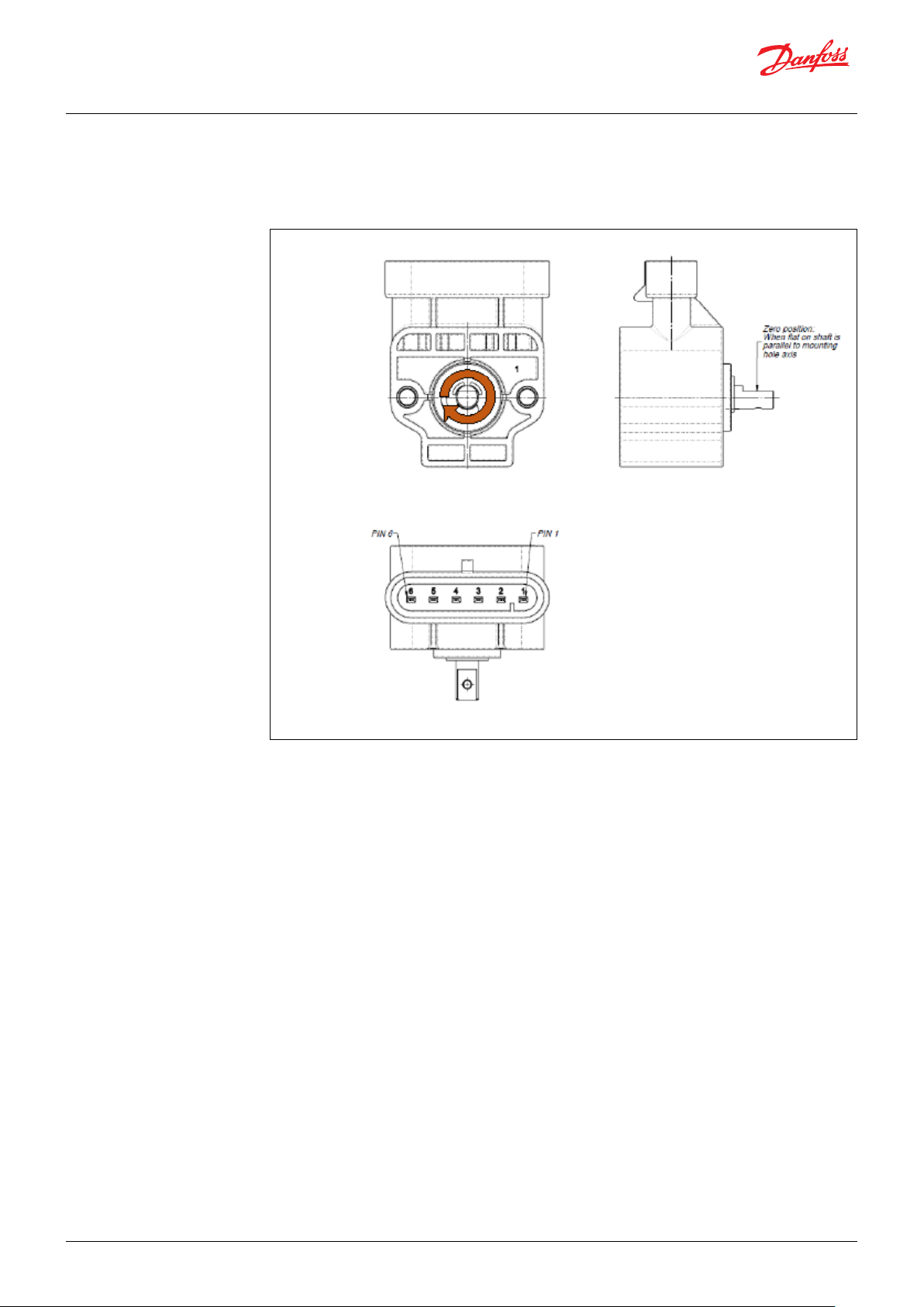
2. Electrical Connections 2.1 Deutsch version with shaft
CONNECTIONS
1.: OV (GND)
2.: + VS (+9 - +36 VDC)
3.: NC
4.: NC
5.: CAN-L
6.: CAN-H
NOTE:
Please make sure that the CANbus is terminated.
The impedance measured between CAN-H and
CAN-L must be 60 ohm that means the cable
must be connected to a 120 ohm resistor on each
ends of the bus line. Internally the tranducer is
not terminated with the resistor of 120 ohm.
Do not confuse the signal lines of the CAN bus,
otherwise communication with the transducer is
impossible.
4 | © Danfoss | DCS (im) | 2019.10
AQ304226795410en-0001010 | IC.PS.P21J2.02
Operation guide | DST X510 and DST X520 Rotary position sensor CANopen
2.2 AMP version with shaft
NOTE:
Please make sure that the CANbus is terminated.
The impedance measured between CAN-H and
CAN-L must be 60 ohm that means the cable
must be connected to a 120 ohm resistor on each
ends of the bus line. Internally the tranducer is
not terminated with the resistor of 120 ohm.
Do not confuse the signal lines of the CAN bus,
otherwise communication with the transducer is
impossible.
CONNECTIONS
1.: OV (GND)
2.: + VS (+9 - +36 VDC)
3.: NC
4.: NC
5.: CAN-L
6.: CAN-H
© Danfoss | DCS (im) | 2019.10
AQ304226795410en-0001010 | IC.PS.P21.J2.02 | 5
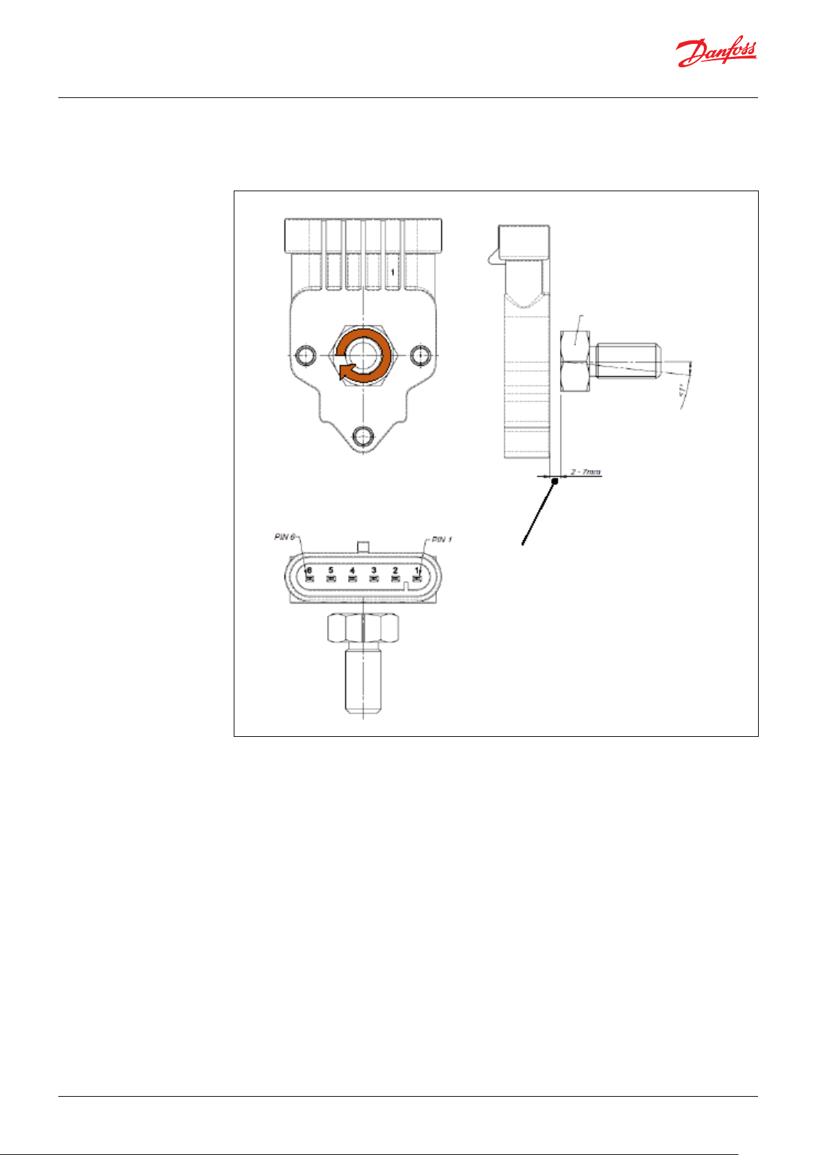
Operation guide | DST X510 and DST X520 Rotary position sensors CANopen
2.3 AMP Superseal version without shaft
M10 CH17 Magnet
< Suggested less than 1°
Air gab
NOTE:
Please make sure that the CANbus is terminated.
The impedance measured between CAN-H and
CAN-L must be 60 ohm that means the cable
must be connected to a 120 ohm resistor on each
ends of the bus line. Internally the tranducer is
not terminated with the resistor of 120 ohm.
Do not confuse the signal lines of the CAN bus,
otherwise communication with the transducer is
impossible.
CONNECTIONS
1.: OV (GND)
2.: + VS (+9 - +36 VDC)
3.: NC
4.: NC
5.: CAN-L
6.: CAN-H
6 | © Danfoss | DCS (im) | 2019.10
AQ304226795410en-0001010 | IC.PS.P21J2.02

Operation guide | DST X510 and DST X520 Rotary position sensor CANopen
2.4 Cable version without shaft
NOTE:
Make sure that the CANbus is terminated. The
inpedance measured between CAN-H and
CAN-L mus be 60 ohm that means the cable
must b e connected to a 120 ohm resistor
on each end of the bus line. Internally the
transducer is not terminated with resistor of
120 ohm. Do not confuse the signal lines of the
CANbus, otherwise communication with the
transducer is impossible.
CONNECTIONS
Black: GROUND
Red: + SUPPLY 1
Yellow: NC
Green: NC
Blue: CAN-L
White: CAN-H
© Danfoss | DCS (im) | 2019.10
AQ304226795410en-0001010 | IC.PS.P21.J2.02 | 7
Operation guide | DST X510 and DST X520 Rotary position sensors CANopen
2.5 Functional Block
Power Management
+ Vs
GND
Angle 1 (CCW)
Hall- CHIP 1
Angle 2(CW)
Hall- CHIP 2
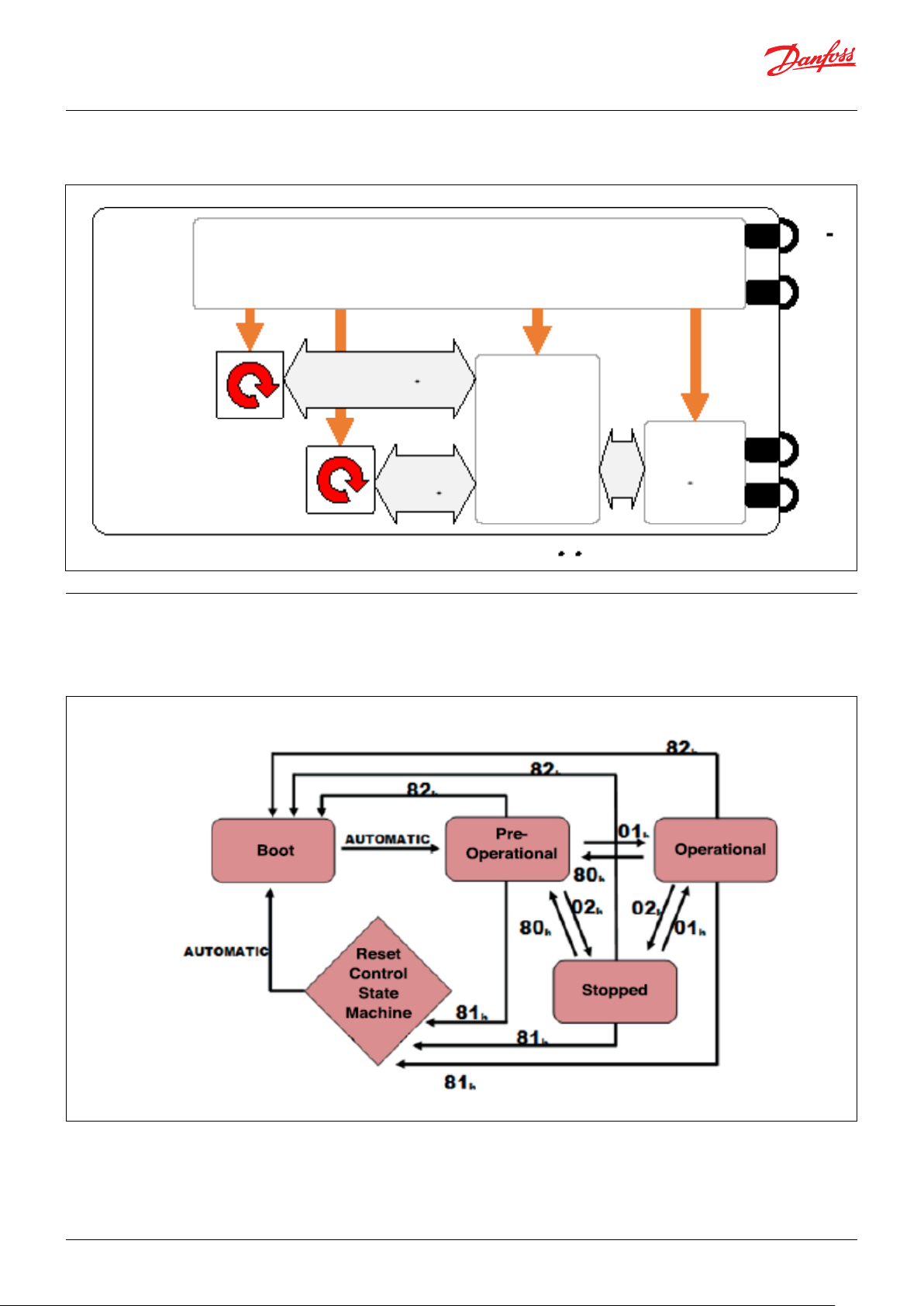
3. Network Management
(NMT)
Data & Diagnostic
Main
Controller
Data &
Diagnostic
The device supports CANopen network
management functionality NMT Slave
(Minimum Boot Up).
CAN
Transceiver
4. Baud rate4. Baud rate4. Baud rate
CAN-H
CAN-L
8 | © Danfoss | DCS (im) | 2019.10
AQ304226795410en-0001010 | IC.PS.P21J2.02
Operation guide | DST X510 and DST X520 Rotary position sensor CANopen
Every CANopen device contains an
international Network Management server that
communicates with an external NMT master.
One device in a network, generally the host,
may act as the NMT master.
Through NMT messages, each CANopen device’s
network management server controls state
changes within its built-in Communication
State Machine.
This is independent from each node’s
operational state machine, which is device
dependant and described in Control State
Machine.
NMT Message COOB-ID Data Byte 1 Data Byte 2
Start Remote Node 0 01h Node-ID*
Stop Remote Node 0 02h Node-ID*
Pre-operational State 0 80h Node-ID*
Reset Node 0 81h Node-ID*
Reset Communica<tion 0 82h Node-ID*
* Node-ID = Drive address (from 1 to 7Fh)
It is important to distinguish a CANopen
device’s operational state machine from its
Communication State Machine.
CANopen sensors and I/O modules, for example,
have completely dierent operational state
machines than servo drives. The “Communication
State Machine” in all CANopen devices, however,
is identical as specied by the DS301.
NMT messages have the highest priority. The 5
NMT messages that control the Communication
State Machine each contain 2 date bytes that
identify the node number and a command to that
node’s state machine.
Table 1 shows the 5 NMT messages surpported,
and Table 2 shows the correct message for
sending these messages.
Table 1
Arbitration
Field
COB-ID RTR Byte 1 Byte 2 Byte 3 Byte 4 Byte 5 Byte 6 Byte 7 Byte 8
000h 0 See table 1 See table 2 These bytes are not sent
4. Baud rate
5. Baud rate
6. Parameter settings
Baud rate can be congurable via Layer Setting
Services and Protocol (LSS) and via SDO
communication (index 0x5999).
The default Baud rate is 250kbit/s.
Node-ID can be congurable via Layer Setting
Services and Protocol (LSS) and via SDO
communication (index 0x5999).
This parameters are called LSS parameters
(marking LSS-PARA).
The resolution can be congurable by using
manufacturing specic objec 0x2100.
All object dictionary parameters (object with
marking PARA) can be saved in a special
section of the internal EEPROM and secured
by checksum calculation.
The special LSS parameters (objects with
marking LL-PARA), also part of the objec
dictionary, will be also saved in a special
section of the internal EEPROM and secured
by checksum calculation.
Date Field
Important Note:
Changing this parameter can disturb the network!
Use the service only if one device is connected to the
network!
The default Node-ID is 7F.
The default resolution is 0.1°.
Important note:
Changing this parameter can disturb the network!
Use the service only if one device is
the network!
Due to the internal architecture of the
microcontroller the parameter write cycles are
limited to 100,000 cycles.
connected to
Table 2
© Danfoss | DCS (im) | 2019.10
AQ304226795410en-0001010 | IC.PS.P21.J2.02 | 9

Operation guide | DST X510 and DST X520 Rotary position sensors CANopen
7. Restore default
parameters
8. Restore default
parameters
9. Error handling
All object dictionary parameters (objects with
marking PARA) can be restored to factory default
values via SDO communication (index
0x1011).
The heartbeat mechanism for this device
isestablished through cyclic transmission of
the heartbeat message done by the heartbeat
producer.
One or more devices in the network are aware
of this heartbeat message. If the herartbeat
cycle fails from the heartbeat producer the local
application on the heartbeat consumer will be
informed about that event.
Heartbeat Message
COB-ID Byte 0
700 + Node-ID Content NMT State
Principle
Emergency messages (EMCY) shall be triggered
by internal errors on device and they are
assigned the highest possible priority to ensure
that they get access to the bus without delay
(EMCY Producer). By default, the EMCY contains
the error eld with pre-dened error numbers
and additional information.
Error Behavior (object 0x4000)
If a serious device failure is detected the object
0x4000 species, to which state the module shall
be set:
=: Pre-operational
1: Mo state change (default)
2: Stopped
The implementation of either guarding or
heartbeat is mandatory.
The device supports Heartbeat Producer
functionality.
The producer heartbeat time is dened in object
0x1017.
EMCY Message
The EMCY COB-ID is dened in object 0x1014.
The EMCY message consists of 8 bytes.
It contains an emergency error code, the
contents of object 0x1001 and 5 byte of
manufacturer specic error code. The device
uses only the 1st byte as manufacturer specic
error code. When a failure ccurs, the reading
of the angular position from the failed channel
presents an out-of-range value, i.e. 0xFFFF.
10 | © Danfoss | DCS (im) | 2019.10
Supported Manufacturer Specic Error Codes (object 0x4001)
Error code Description
0000 0000 No error
0000 0001 Angle 1 sensor chip error
0000 0010 Angle 2 sensor chip error
0000 0100 Angle mismatch (Angle 1 vs Angle 2) error, object 0x2103
NOT IMPLEMENTED
0001 0000 Program checksum error
0100 0000 LSS Parameter checksum error
1000 0000 Magnetic eld too high/low
AQ304226795410en-0001010 | IC.PS.P21J2.02

Operation guide | DST X510 and DST X520 Rotary position sensor CANopen
10. SDO communication
COB-ID DLC Byte 1 Byte 2 Byte 3 Byted 4 Byte 5 Byte 6 Byte 7 Byte 8
600+Node-ID 8 CMD Index Sub-Index Data Data Data Data
COB-ID DLC Byte 1 Byte 2 Byte 3 Byted 4 Byte 5 Byte 6 Byte 7 Byte 8
5807+Node-ID 8 RES Index Sub-Index Data Data Data Data
The device fulls the SDO Server functionality.
Witi Service Data Object (S.D.O.) the access
to entries of a device Object Dictionary is
provided. As these entries may contain data of
arbitrary size and data typ SDOs can be used
to transfer multiple data sets from a client to a
server and vice versa.
Structure of SDO-request by the Master
Structure of SDO-answer by the Slave
Write Access, Data Transfer form Host to Slave
Each access to object dictionary is checked
by the slave for validity. Any write access to
nonexistent objects, to read - only objects or
with a non-corresponding data format are
rejected and answered with a corresponding
error message.
CMD determines the direction of data transfer and
the size of the data object:
23 hex Sending of 4-byte data
(bytes 5 - 8 contian a 32 bit value)
2B hex Sending of 2-byte data
(bytes 5, 6 contain a 16-bit value
2F hex Sending of 1-byte data
(byte 5 contians an 8-bit value)
Read Access, Data Transfer form Slave to Host
Any read access to non-existing objects is
answered with an error message.
CMD determines the direction of data transfer:
40 hex read access (in any case)
The Slave answers:
RES Response of the slave:
42 hex Bytes used by node when replying to
read command with 4 or less data
43 hex Bytes 5 - 8 contain a 32-bit value
4B hex Bytes 5, 6 contain a 16-bit value
4F hex Byte 5 contains an 8-bit value
80 hex Error
11. PDO communication
and Angle calculation
Byte Byte 1 Byte 2 Byte 3 Byte 4
ANGLE 1
Description
object
(0x2110.1)
High-Byte
The Slave answers:
RES response of the slave:
60 hex Data sent successfully
80 hex Error
Transmit PDO #0
This PDO transmits asynchronously the
position value of the angle sensor. Default
transmission rate is 100 ms. The Tx PDO#0
shall be transmitted cyclically, if the cyclic
timer (object 0x1800.5) is programmed > 0.
Values between 1 ms and 65535 ms shall
be selectable by parameter settings. The Tx
PDO#0 will be transmitted by entering the
“Operational” state.
ANGLE 1
object
(0x2110.2)
Low-Byte
TxPDO# with default mapping when object 0x5001 = 0 (big endian)
ANGLE 2
object
(0x2110.3)
High-Byte
ANGLE 2
object
(0x2110.4)
Low-Byte
Byte 5
Byte 6
Byte 7
(0xFF)
Byte 8
Error Code
(object 0x4001)
© Danfoss | DCS (im) | 2019.10
AQ304226795410en-0001010 | IC.PS.P21.J2.02 | 11

Operation guide | DST X510 and DST X520 Rotary position sensors CANopen
Byte Byte 1 Byte 2 Byte 3 Byte 4
ANGLE 1
Description
Example of PDO mapping is reported in the case of Angle 1 = 0.00° and Angle 2 = 359.99°
object
(0x2110.1)
Low-Byte
TxPDO# with default mapping when object 0x5001 = 0 (little endian)
ANGLE 1
object
(0x2110.2)
High-Byte
ANGLE 2
object
(0x2110.3)
Low-Byte
ANGLE 2
object
(0x2110.4)
High-Byte
Byte 5
Byte 6
Byte 7
(0xFF)
Byte 8
Error Code
(object 0x4001)
12 | © Danfoss | DCS (im) | 2019.10
AQ304226795410en-0001010 | IC.PS.P21J2.02

Operation guide | DST X510 and DST X520 Rotary position sensor CANopen
Reading resolution ± 0.1° (see manufacturing
specic object 0x2100 and example (7) at the
end of this manual)
Example of PDO mapping for:
Angle 1 = 0.-0° and Angle 2 = 359.9° (Node-ID
= 02h, resolution 0.1°, zero degree point = 0.0°,
CCW and big endian)
ID Byte 1 Byte 2 Byte 3 Byte 4 Byte 5 Byte 6 Byte 7 Byte 8
182h 00h 00h 0Eh 0Fh FFh FFh FFh 00h
Angle 1:
Byte 1 MSB (00h) = 00h Byte 2 LSB (00h) = 00h
Angle 1 = 0000h to decimal 0d (resolution 0.1°)
= 0.0°
Reading resolution ± 0.01° (see
manufacturing specic object 0x2100 and
example (8) at the end of this manual)
Example of PDO mapping for:
Angle 1 = 0.-0° and Angle 2 = 359.9° (Node-ID
= 02h, resolution 0.1°, zero degree point = 0.0°,
CCW and big endian)
ID Byte 1 Byte 2 Byte 3 Byte 4 Byte 5 Byte 6 Byte 7 Byte 8
182h 00h 00h 8Ch 9Fh FFh FFh FFh 00h
Angle 1:
Byte 1 MSB (00h) = 00h Byte 2 LSB (00h) = 00h
Angle 1 = 0000h to decimal 0d (resolution 0.1°)
= 0.0°
Example of PDO mapping is reported in the case of Angle 1 =270.0° and Angle 2 = 90.0°
Angle 2:
Byte 3 MSB (00h) = 0Eh Byte 4 LSB (00h) = 0Fh
Angle 2 = 0E0Fh to decimal 3599d (resolution
0.1°) = 359.9°
Angle 2:
Byte 3 MSB (00h) = 0Ch Byte 4 LSB (00h) = 9Fh
Angle 2 = 8C9Fh to decimal 35999d (resolution
0.1°) = 359.9°
© Danfoss | DCS (im) | 2019.10
AQ304226795410en-0001010 | IC.PS.P21.J2.02 | 13

Operation guide | DST X510 and DST X520 Rotary position sensors CANopen
Reading resolution ± 0.1° (see manufacturing
specic object 0x2100 and example (7) at the
end of this manual)
Example of PDO mapping for:
Angle 1 = 270.-0° and Angle 2 = 90.0° (Node-ID
= 02h, resolution 0.1°, zero degree point = 0.0°,
CCW and big endian)
ID Byte 1 Byte 2 Byte 3 Byte 4 Byte 5 Byte 6 Byte 7 Byte 8
182h 0Ah 8Ch 03h 84h FFh FFh FFh 00h
Angle 1:
Byte 1 MSB (00h) = 0Ah Byte 2 LSB (00h) = 8Ch
Angle 1 = 0A8Ch to decimal 0d (resolution 0.1°)
= 270.0°
Reading resolution ± 0.01° (see
manufacturing specic object 0x2100 and
example (8) at the end of this manual)
Example of PDO mapping for:
Angle 1 = 270.-0° and Angle 2 = 90.0° (Node-ID
= 02h, resolution 0.1°, zero degree point = 0.0°,
CCW and big endian)
ID Byte 1 Byte 2 Byte 3 Byte 4 Byte 5 Byte 6 Byte 7 Byte 8
182h 69h 78h 23h 28h FFh FFh FFh 00h
Angle 1:
Byte 1 MSB (00h) = 69h Byte 2 LSB (00h) = 78h
Angle 1 = 6978h to decimal 27000d (resolution
0.1°) 270.0°
Angle 2:
Byte 3 MSB (00h) = 03h Byte 4 LSB (00h) = 84h
Angle 2 = 0384h to decimal 900d (resolution
0.1°) = 90.0°
Angle 2:
Byte 3 MSB (00h) = 23h Byte 4 LSB (00h) = 28h
Angle 2 = 90.0°
Angle calculation for ANGLE 1 and ANGLE 2
Fig. 1 Angle computation
14 | © Danfoss | DCS (im) | 2019.10
AQ304226795410en-0001010 | IC.PS.P21J2.02

Operation guide | DST X510 and DST X520 Rotary position sensor CANopen
ID Byte 1 Byte 2 Byte 3 Byte 4 Byte 5 Byte 6 Byte 7 Byte 8
182h 00h 00h 0Eh 0Fh FFh FFh FFh 00h
ANGLE 1
Important note:
The two angles Angle 1 and Angle 2 are
obtained independently from each other (i.e.
in DST X510/DST X520 series contactless rotary
sensors there are two on-board HALL chips) in a
sort of redundant conguration.
12. CANopen features
summary
Sub
Index
1000h Device Prole Unsigned 32 Ro 0x00000000 No standardized device prol adapted
1001h Error Register Unsigned 8 Ro 0x00 Always ZERO
1008h
1009h
100Ah
1010h
1011h
1014h 0 Emergency ID Unsigned 32 Rw 0x80+Node-ID
1017h
1018h
Ro = the parameter can be read only
Rw = the parameter can be read and also written
Wo = the parameter can be written only
Index
Name Type Access Default value Comments
Manufacturer Device
Name
Manufacturer Hardware
Version
Manufacturer Software
Version
0 Number of entries Unsigned 8 Ro 1 “save” (0x65766173) to store all
1
Save all parameters Unsigned 32 Rw
0 Restore default
parameters
1 Restore all parameters Unsigned 32 Rw
0
Producer time/Heart beat Unsigned 16 Rw 0
0 Identity object Unsigned 8 Ro 4
1 Vendor ID Unsigned 32 Ro 0x0000093
2 Product code Unsigned 32 Ro 0x0000064
3 Revision number Unsigned 32 Ro 0x0000001
4 Serial number Unsigned 32 Ro 0x0000000
Communication Prole
The parameters which are critical for
communication are determined in the
Communication prole.
This area is common for all CANopen devices.
ANGLE 2
String Ro “GRA” or “GRN”
String Ro “1.00”
String Ro “1.14”
Unsigned 8 Ro
Rewfer to Danfoss data sheet:
GRA: DST X510 contactless rotary
sensor with shaft
GRN: DST X520 Contactless rotary
sensor without shaft
parameters (objects with marking
PARA)
“load” (0x64616F6C) to restore all
parameters (objects with PARA and
LSS-PARA)
Min. = 0 & Max. = 65536 with unit =
1ms; If 0: NOT USED
Refer to Vendor ID: 0x0000093
© Danfoss | DCS (im) | 2019.10
AQ304226795410en-0001010 | IC.PS.P21.J2.02 | 15

Operation guide | DST X510 and DST X520 Rotary position sensors CANopen
Index
1200h
1800h
1A00h
Sub
Index
Name Type Access Default value Comments
SDO Server Parameter
0 Number of entries Unsigned 8 Ro 2
1 COB-ID Client to Server (Tx) Unsigned 32 Ro 0x600+Node-ID
2 COB-ID Server to Server (tx) Unsigned 32 Ro 0x580+Node-ID
0 1
st
Transmit PDO Parameter Unsigned 8 Ro
Default value
Ro
Comments Ro
1 COB-ID Unsigned 32 Ro 180h + Node-ID Comments 180h, Node-ID
2 Transmission Type Unsigned 8 Rw 253 Asynchronous transmission
3 Inhibit Time Unsigned 16 Ro 0 Min. = 0 & Max. = 65535
4 Reserved // // 14 Min. 14 Max. 14 with unit 1 ms
5 Timer Unsigned 16 Rw 100 Min. = 4 & Max. = 65535
TxPDO Mapping Parameter
0 Number of entries Unsigned 8 Ro 8
1 1
2 2
3 3
4 4
5 5
6 6
7 7
8 4
st
Mapped Object Unsigned 32 Ro 0x21100108
nd
Mapped Object Unsigned 32 Ro 0x21100208
rd
Mapped Object Unsigned 32 Ro 0x21100308
th
Mapped Object Unsigned 32 Ro 0x21100408
th
Mapped Object Unsigned 32 Ro 0x21100508
th
Mapped Object Unsigned 32 Ro 0x21100608
th
Mapped Object Unsigned 32 Ro 0x21100708
th
Mapped Object Unsigned 32 Ro 0x40010008
Objects:
0x2110.1
0x2110.2
0x2110.3
0x2110.4
0x2110.5
0x2110.6
0x2110.7
0x4001.0
2 Angle 2 Zero degree point Unsigned 16 Ro 0
Ro = the parameter can be read only
Rw = the parameter can be read and also written
Wo = the parameter can be written only
16 | © Danfoss | DCS (im) | 2019.10
AQ304226795410en-0001010 | IC.PS.P21J2.02

Operation guide | DST X510 and DST X520 Rotary position sensor CANopen
Manufacturer Specic Prole Objects
In this section you will nd the manufacturer
specic prole indices for transducers.
Index Sub
Index
2000h 0 Number of entries Unsigned 8 Ro 2 Angle sensor 1 and Angle sensor 2 in a single
1 Angle 1 Sensor Value Unsigned 16 Ro 0
2 Angle 2 Sensor Value Unsigned 16 Ro 0
2001h 0 Number of entries Unsigned 8 Ro 2 Min. = 0 & Max. = 255
1 Angle 1 FILTER Unsigned 8 Rw 0
2 Angle 2 FILTER Unsigned 8 Rw 0
0 Number of entries Unsigned 8 Ro 3
1 Angle 1 Process data Unsigned 16 Ro 0 Angle 1 Process data
2 Angle 2 Process data Unsigned 16 Ro 0 Angle 2 Process data
3
2100h 0 Number of entries Unsigned 8 Ro 2 The Angle 1 and 2:
1 Angle 1 Resolution Unsigned 16 Rw 100
2 Angle 2 Resolution Unsigned 16 Rw 100
2101h 0 Number of entries Unsigned 8 Ro 2 Angle 1 & 2 Zero Degree Point have to be in
1
2102h 0 Number of entries Unsigned 8 Ro 2 0: CCW
1 Angle 1 Unsigned 8 Rw X
2 Angle 2 Unsigned 8 Rw X
2103h Angle maximum
2110h 0 Number of entries Unsigned 8 Ro 4
1
2
3
4
Name Type Access Default
Angle Value
Angle Filter Function
Angle Sensor Process Data
Angle 1 & 2 Process
data
Angle 1 Zero degree
point
dierence
Angle 1 Output
Value Byte 0
Angle 1 Output
Value Byte 1
Angle 1 Output
Value Byte 0
Angle 1 Output
Value Byte 0
Unsigned 32 Ro 0
Angle Resolution
Angle Zero Degree Point
Unsigned 16 Ro 0
Angle Clockwise
Angle 1 and Angle 2 Values
Unsigned 8 0
Unsigned 8 0
Unsigned 8 0
Unsigned 8 0
value
0
Comments
chip with 360° fullscale and a resolution of
about 0.022°/bit
Min. = 0 & Max. = 16383
0: Not used
NOT IMPLEMENTED
Angle 1 & 2 Process data sent at the same time
Resolution accepted values are:
1000d: 1° bit; 100d: 0.1° bit; 22d: 0.01° bit
(14 bits eective resolution 0.02°)
relationg with the maximum allowed degree
Min. = 0 & Max. = 16383
1: CW
According to the ordering code
NOT IMPLEMENTED
Unit: 0x2100
MSB when PDO coding Big Endian
(Index 0x500) is used Min.= 0 & Max. = 255
Unit: 0x2100
MSB when PDO coding Big Endian
(Index 0x500) is used Min.= 0 & Max. = 255
Unit: 0x2100
MSB when PDO coding Big Endian
(Index 0x500) is used Min.= 0 & Max. = 255
Unit: 0x2100
MSB when PDO coding Big Endian
(Index 0x500) is used Min.= 0 & Max. = 255
© Danfoss | DCS (im) | 2019.10
AQ304226795410en-0001010 | IC.PS.P21.J2.02 | 17

Operation guide | DST X510 and DST X520 Rotary position sensors CANopen
Index Sub
Index
4000h Error
4001h
5000h Automatic NMT
5001h
5999h 0 Number of entries Unsigned 8 Ro 3
1 Baud rate - LSS-PARA Unsigned 16 Rw 250
2 Node-ID - LSS-PARA Unsigned 8 Rw 2
3 Store - LSS-PARA Unsigned 32 Wo
Ro = the parameter can be read only
Rw = the parameter can be read and also written
Wo = the parameter can be written only
Name Type Access Default
Angle Value
Behavior - PARA
Error code Unsigned 8 Ro 0
Start after Power-on
- PARA
PDO coding standard
used - PARA
Unsigned 8 Rw 1
Unsigned 8 Rw 1
Undesigned Rw 0
LSS Parameter
value
Comments
0: Pre-operational, 1: No state change
2: Stopped; Min. = 0 & Max. = 255
0000 0000 No error
0000 0001 Angle 1 sensor chip error
0000 0010 Angle 2 sensor chip error
0000 0100 Angle mismatch (Angle 1 vs Angle 2)
error, object 0x2103 NOT IMPLEMEMTED
0001 0000 Program checksum error
0100 0000 LSS Parameter checksum error
1000 0000 Magnetic elsd too high/low
0: Not activated
1: Little endian
Min. = 0 & Max. = 1
0: Big endian
1: Little Endian
Min. = 0 & Max. = 1
Possible values:
50 kbit/s
125 kbit/s
250 kbit/s
500 kbit/s
800 kbit/s
1000 kbit/s
Min. = 50 & Max. = 1000
IMPORTANT: use this service only if one device
is connected to the network
Min. = 1 & Max. = 127
IMPORTANT: use this service only if one device
is connected to the network
“Save” (0x65766173) to store all LSS parameters
(object with marking LSS-PARA)
IMPORTANT: use this service only if one device
is connected to the network
I
18 | © Danfoss | DCS (im) | 2019.10
AQ304226795410en-0001010 | IC.PS.P21J2.02

Operation guide | DST X510 and DST X520 Rotary position sensor CANopen
13. Communication
examples
COB-ID DLC Byte 1 Byte 2 Byte 3 Byte 4 Byte 5 Byte 6 Byte 7 Byte 8
600+Node-ID 8 CMD Index Sub-Index Data
COB-ID DLC Byte 1 Byte 2 Byte 3 Byte 4 Byte 5 Byte 6 Byte 7 Byte 8
580+Node-ID 8 CMD Index Sub-Index Data
Example 1: How to change the Baud Rate
Setting from 250 kbaud to 500 kbaud
With Service Data Object (S.D.O) the access
to entries of a device Object Dictionary is
provided. As these entries may contain data of
arbitrary size and data type SDOs can be used
to transfer multiple data sets from a client to a
server and vice versa.
Structure of SDO-request by the Master
CMD determines the direction of data transfer
and the size of the data object:
23 hex Sending of 4-byte data (bytes 5 - 8
contain a 32 bith value)
2B hex Sending of 2-byte data (bytes 5, 6
contain a 16-bit value)
2F hex Sending of 1-byte data (byte 5 contains
an 8-bit value)
Structure of SDO-answer by the Slave
RES Response of Slave:
60 hex Data sent successfully
80 hex Error
Write (in the example the Node-ID = 0x03)
COB-ID Byte 1 Byte 2 Byte 3 Byte 4 Byte 5 Byte 6 Byte 7 Byte 8
603h 2Bh 99h 59h 01h F4h 01h 00h 00h
5999h LSS Parameter
0 Number of entries Unsigned 8 Ro 3
Possible values:
50 kbit/s
125 kbit/s
250 kbit/s
Baud rate -
1
LSS-PARA
2 Node-ID - LSS-PARA Unsigned 8 Rw 2
3 Store - LSS-PARA IUnsigned 32 Wo
Unsigned 16 Rw 500
500 kbit/s
800 kbit/s
1000 kbit/s
Min. = 50 & Max. = 1000
IMPORTANT: use this service only if one device is
connected to the network
Min. = 1 & Max. = 127
IMPORTANT: use this service only if one device is
connected to the network
“Save” (0x65766173) to store all LSS parameters
(object with marking LSS-PARA)
IMPORTANT: use this service only if one device is
connected to the network
© Danfoss | DCS (im) | 2019.10
AQ304226795410en-0001010 | IC.PS.P21.J2.02 | 19

Operation guide | DST X510 and DST X520 Rotary position sensors CANopen
The supported baudrate are listed in the
following table:
Byte 5 Byte 6 Baudrate
32h 00h 50 Kbaud
7Dh 00h 125 Kbaud
FAh 00h 250 Kbaud
F4h 01h 500 Kbaud
20h 03h 800 Kbaud
E8h 03h 1Mbaud
The answer after successful storing you will receive is:
ID Byte 1 Byte 2 Byte 3 Byte 4 Byte 5 Byte 6 Byte 7 Byte 8
583h 60h 99h 59h 01h 00h 00h 00h 00h
With the aim to save new Baud Rate write the “save” command as below:
Write (in the example the Node-ID = 0x03)
ID Byte 1 Byte 2 Byte 3 Byte 4 Byte 5 Byte 6 Byte 7 Byte 8
603h 23h 99h 59h 03h 73h 61h 76h 65h
Note: save command is given by sending the code:
73h 61h 76h 65h
Where:
73h = ASCII code “s”
61h = ASCII code “a”
76h = ASCII code “v”
65h = ASCII code “e”
The answer after successfull storing you will receive is:
ID Byte 1 Byte 2 Byte 3 Byte 4 Byte 5 Byte 6 Byte 7 Byte 8
583h 60h 99h 59h 03h 00h 00h 00h 00h
IMPORTANT NOTE:
After setting the new entries a reset must be
made so that the new entries become valid
(switch off the module for a short time).
20 | © Danfoss | DCS (im) | 2019.10
AQ304226795410en-0001010 | IC.PS.P21J2.02

Operation guide | DST X510 and DST X520 Rotary position sensor CANopen
Example 2: How to change the ID-Node from
0x03h (3d) to 0x06h (6d)
With Service Data Object (S.D.O) the access
to entries of a device Object Dictionary is
provided. As these entries may contain data of
arbitrary size and data type SDOs can be used
to transfer multiple data sets from a client to a
server and vice versa.
Structure of SDO-request by the Master
COB-ID DLC Byte 1 Byte 2 Byte 3 Byte 4 Byte 5 Byte 6 Byte 7 Byte 8
600+Node-ID 8 CMD Index Sub-Index Data
CMD determines the direction of data transfer
and the size of the data object:
23 hex Sending of 4-byte data (bytes 5 - 8
contain a 32 bit value)
2B hex Sending of 2-byte data (bytes 5, 6
contain a 16-bit value)
2F hex Sending of 1-byte data (byte 5 contains
an 8-bit value)
Structure of SDO-answer by the Slave
COB-ID DLC Byte 1 Byte 2 Byte 3 Byte 4 Byte 5 Byte 6 Byte 7 Byte 8
580+Node-ID 8 CMD Index Sub-Index Data
RES Response of Slave:
60 hex Data sent successfully
80 hex Error
Write (in the example the Node-ID = 0x03)
COB-ID Byte 1 Byte 2 Byte 3 Byte 4 Byte 5 Byte 6 Byte 7 Byte 8
603h 2Bh 99h 59h 02h F4h 06h 00h 00h
5999h LSS Parameter
0 Number of entries Unsigned 8 Ro 3
Possible values:
50 kbit/s
125 kbit/s
250 kbit/s
Baud rate -
1
LSS-PARA
2 Node-ID - LSS-PARA Unsigned 8 Rw 6
3 Store - LSS-PARA IUnsigned 32 Wo
Unsigned 16 Rw 250
500 kbit/s
800 kbit/s
1000 kbit/s
Min. = 50 & Max. = 1000
IMPORTANT: use this service only if one device is
connected to the network
Min. = 1 & Max. = 127
IMPORTANT: use this service only if one device is
connected to the network
“Save” (0x65766173) to store all LSS parameters
(object with marking LSS-PARA)
IMPORTANT: use this service only if one device is
connected to the network
© Danfoss | DCS (im) | 2019.10
AQ304226795410en-0001010 | IC.PS.P21.J2.02 | 21

Operation guide | DST X510 and DST X520 Rotary position sensors CANopen
To supported Node-ID are 0x01 to 0x7F
The answer after successful storing you will receive is:
ID Byte 1 Byte 2 Byte 3 Byte 4 Byte 5 Byte 6 Byte 7 Byte 8
583h 60h 99h 59h 02h 00h 00h 00h 00h
With the aim to save new Baud Rate write the “save” command as below:
Write (in the example the Node-ID = 0x03)
ID Byte 1 Byte 2 Byte 3 Byte 4 Byte 5 Byte 6 Byte 7 Byte 8
603h 23h 99h 59h 03h 73h 61h 76h 65h
Note: save command is given by sending the code:
73h 61h 76h 65h
Where:
73h = ASCII code “s”
61h = ASCII code “a”
76h = ASCII code “v”
65h = ASCII code “e”
The answer after successfull storing you will receive is:
ID Byte 1 Byte 2 Byte 3 Byte 4 Byte 5 Byte 6 Byte 7 Byte 8
583h 60h 99h 59h 03h 00h 00h 00h 00h
IMPORTANT NOTE:
After setting the new entries a reset must be
made so that the new entries become valid
(switch off the module for a short time).
22 | © Danfoss | DCS (im) | 2019.10
AQ304226795410en-0001010 | IC.PS.P21J2.02

Operation guide | DST X510 and DST X520 Rotary position sensor CANopen
Example 3: How to activate an automatic NMT
Start after Power ON (the PDO will be send
automatically after power ON)
With Service Data Object (S.D.O) the access
to entries of a device Object Dictionary is
provided. As these entries may contain data of
arbitrary size and data type SDOs can be used
to transfer multiple data sets from a client to a
server and vice versa.
Structure of SDO-request by the Master
COB-ID DLC Byte 1 Byte 2 Byte 3 Byte 4 Byte 5 Byte 6 Byte 7 Byte 8
600+Node-ID 8 CMD Index Sub-Index Data
CMD determines the direction of data transfer
and the size of the data object:
23 hex Sending of 4-byte data (bytes 5 - 8
contain a 32 bit value)
2B hex Sending of 2-byte data (bytes 5, 6
contain a 16-bit value)
2F hex Sending of 1-byte data (byte 5 contains
an 8-bit value)
Structure of SDO-answer by the Slave
COB-ID DLC Byte 1 Byte 2 Byte 3 Byte 4 Byte 5 Byte 6 Byte 7 Byte 8
580+Node-ID 8 CMD Index Sub-Index Data
RES Response of Slave:
60 hex Data sent successfully
80 hex Error
Write (in the example the Node-ID = 0x03)
COB-ID Byte 1 Byte 2 Byte 3 Byte 4 Byte 5 Byte 6 Byte 7 Byte 8
603h 2Fh 00h 50h 00h 01h 00h 00h 00h
Object:
5000h
ID Byte 1 Byte 2 Byte 3 Byte 4 Byte 5 Byte 6 Byte 7 Byte 8
603h 23h 10h 10h 01h 73h 61h 76h 65h
73h 61h 76h 65h
ID Byte 1 Byte 2 Byte 3 Byte 4 Byte 5 Byte 6 Byte 7 Byte 8
583h 60h 10h 10h 01h 00h 00h 00h 00h
Automatic NMT Start
after Power-On - PARA
With the aim to save new Baud Rate write the “save” command as below:
Write (in the example the Node-ID = 0x03)
Where:
73h = ASCII code “s”
61h = ASCII code “a”
76h = ASCII code “v”
65h = ASCII code “e”
The answer after successfull storing you will receive is:
IMPORTANT NOTE:
After setting the new entries a reset must be
made so that the new entries become valid
(switch off the module for a short time).
Unsigned 8 Rw 1
Note: save command is given by sending the code:
0: Not activated
1: Activated
Min. = 0 & Max. = 1
© Danfoss | DCS (im) | 2019.10
AQ304226795410en-0001010 | IC.PS.P21.J2.02 | 23

Operation guide | DST X510 and DST X520 Rotary position sensors SAE J1939
Example 4: How to change the PDO rate (time
interval) from 100 ms to 20 ms
With Service Data Object (S.D.O) the access
to entries of a device Object Dictionary is
provided. As these entries may contain data of
arbitrary size and data type SDOs can be used
to transfer multiple data sets from a client to a
server and vice versa.
Structure of SDO-request by the Master
COB-ID DLC Byte 1 Byte 2 Byte 3 Byte 4 Byte 5 Byte 6 Byte 7 Byte 8
600+Node-ID 8 CMD Index Sub-Index Data
CMD determines the direction of data transfer
and the size of the data object:
23 hex Sending of 4-byte data (bytes 5 - 8
contain a 32 bit value)
2B hex Sending of 2-byte data (bytes 5, 6
contain a 16-bit value)
2F hex Sending of 1-byte data (byte 5 contains
an 8-bit value)
Structure of SDO-answer by the Slave
COB-ID DLC Byte 1 Byte 2 Byte 3 Byte 4 Byte 5 Byte 6 Byte 7 Byte 8
580+Node-ID 8 CMD Index Sub-Index Data
RES Response of Slave:
60 hex Data sent successfully
80 hex Error
Write (in the example the Node-ID = 0x03)
COB-ID Byte 1 Byte 2 Byte 3 Byte 4 Byte 5 Byte 6 Byte 7 Byte 8
603h 2Bh 00h 18h 05h 14h 00h 00h 00h
Object:
0
1 COB-ID Unsigned 32 Ro 180h+Node-ID
1800h
2 Transmission Type Unsigned 8 Rw 254 PAsynchronous transmission
3 Inhibit Time Unsigned 16 Ro 0 Min. = 0 & Max. = 65535 with unit = 1 ms
4 Reserved // //
5 Timer Unsigned 16 Rw 20 Min. = 4 & Max. = 65535 with unit = 1 ms
ID Byte 1 Byte 2 Byte 3 Byte 4 Byte 5 Byte 6 Byte 7 Byte 8
583h 60h 00h 18h 05h 00h 00h 00h 00h
1st Transmit PDO
Parameter
The answer after succesful storing you will receive is:
Unsigned 8 Ro
24 | © Danfoss | DCS (im) | 2019.10
AQ304226795410en-0001010 | IC.PS.P21J2.02

Operation guide | DST X510 and DST X520 Rotary position sensor CANopen
With the aim to save new Baud Rate write the “save” command as below:
Write (in the example the Node-ID = 0x03)
ID Byte 1 Byte 2 Byte 3 Byte 4 Byte 5 Byte 6 Byte 7 Byte 8
603h 23h 10h 10h 01h 73h 61h 76h 65h
Note: save command is given by sending the code:
73h 61h 76h 65h
Where:
73h = ASCII code “s”
61h = ASCII code “a”
76h = ASCII code “v”
65h = ASCII code “e”
The answer after successfull storing you will receive is:
ID Byte 1 Byte 2 Byte 3 Byte 4 Byte 5 Byte 6 Byte 7 Byte 8
583h 60h 10h 10h 01h 00h 00h 00h 00h
IMPORTANT NOTE:
After setting the new entries a reset must be
made so that the new entries become valid
(switch off the module for a short time).
© Danfoss | DCS (im) | 2019.10
AQ304226795410en-0001010 | IC.PS.P21.J2.02 | 25

Operation guide | DST X510 and DST X520 Rotary position sensors SAE J1939
Example 5: How to set the ZERO degree point
to Angle 1 (example with resolution ±0.1°)
With Service Data Object (S.D.O) the access
to entries of a device Object Dictionary is
provided. As these entries may contain data of
arbitrary size and data type SDOs can be used
to transfer multiple data sets from a client to a
server and vice versa.
Structure of SDO-request by the Master
COB-ID DLC Byte 1 Byte 2 Byte 3 Byte 4 Byte 5 Byte 6 Byte 7 Byte 8
600+Node-ID 8 CMD Index Sub-Index Data
CMD determines the direction of data transfer
and the size of the data object:
23 hex Sending of 4-byte data (bytes 5 - 8
contain a 32 bit value)
2B hex Sending of 2-byte data (bytes 5, 6
contain a 16-bit value)
2F hex Sending of 1-byte data (byte 5 contains
an 8-bit value)
Structure of SDO-answer by the Slave
COB-ID DLC Byte 1 Byte 2 Byte 3 Byte 4 Byte 5 Byte 6 Byte 7 Byte 8
580+Node-ID 8 CMD Index Sub-Index Data
RES Response of Slave:
60 hex Data sent successfully
80 hex Error
Write (in the example the Node-ID = 0x03)
If the actual value of the Angle 1 is 02h 65 h =
0265 h = 613 d = 61.3° with the aim to move the
Angle 1 to ZERO add to Byte 5 and Byte 6 the
values below:
COB-ID Byte 1 Byte 2 Byte 3 Byte 4 Byte 5 Byte 6 Byte 7 Byte 8
603h 2Bh 01h 21h 01h 65h 02h 00h 00h
Object:
Angle ZERO
Degree Point
The Angle 1 and Angle 2 ZERO Degree Point
have to be in relation with the mas. allowed
degree
Min. = 0 & Max. = 16383
2101h
0 Number of entries Unsigned 8 Ro 2
1
2
Angle 1 ZERO
Degree Point
Angle 2 ZERO
Degree Point
Unsigned 16 Rw 613
Unsigned 16 Rw 0
The answer after succesful storing you will receive is:
ID Byte 1 Byte 2 Byte 3 Byte 4 Byte 5 Byte 6 Byte 7 Byte 8
583h 60h 01h 21h 01h 00h 00h 00h 00h
26 | © Danfoss | DCS (im) | 2019.10
AQ304226795410en-0001010 | IC.PS.P21J2.02

Operation guide | DST X510 and DST X520 Rotary position sensor CANopen
With the aim to save new Baud Rate write the “save” command as below:
Write (in the example the Node-ID = 0x03)
ID Byte 1 Byte 2 Byte 3 Byte 4 Byte 5 Byte 6 Byte 7 Byte 8
603h 23h 10h 10h 01h 73h 61h 76h 65h
Note: save command is given by sending the code:
73h 61h 76h 65h
Where:
73h = ASCII code “s”
61h = ASCII code “a”
76h = ASCII code “v”
65h = ASCII code “e”
The answer after successfull storing you will receive is:
ID Byte 1 Byte 2 Byte 3 Byte 4 Byte 5 Byte 6 Byte 7 Byte 8
583h 60h 10h 10h 01h 00h 00h 00h 00h
IMPORTANT NOTE:
After setting the new entries a reset must be
made so that the new entries become valid
(switch off the module for a short time).
© Danfoss | DCS (im) | 2019.10
AQ304226795410en-0001010 | IC.PS.P21.J2.02 | 27

Operation guide | DST X510 and DST X520 Rotary position sensors SAE J1939
Example 6: How to set the ZERO degree point
to Angle 2 (example with resolution ±0.1°)
With Service Data Object (S.D.O) the access
to entries of a device Object Dictionary is
provided. As these entries may contain data of
arbitrary size and data type SDOs can be used
to transfer multiple data sets from a client to a
server and vice versa.
Structure of SDO-request by the Master
COB-ID DLC Byte 1 Byte 2 Byte 3 Byte 4 Byte 5 Byte 6 Byte 7 Byte 8
600+Node-ID 8 CMD Index Sub-Index Data
CMD determines the direction of data transfer
and the size of the data object:
23 hex Sending of 4-byte data (bytes 5 - 8
contain a 32 bit value)
2B hex Sending of 2-byte data (bytes 5, 6
contain a 16-bit value)
2F hex Sending of 1-byte data (byte 5 contains
an 8-bit value)
Structure of SDO-answer by the Slave
COB-ID DLC Byte 1 Byte 2 Byte 3 Byte 4 Byte 5 Byte 6 Byte 7 Byte 8
580+Node-ID 8 CMD Index Sub-Index Data
RES Response of Slave:
60 hex Data sent successfully
80 hex Error
Write (in the example the Node-ID = 0x03)
If the actual value of the Angle 1 is 02h 65 h =
0265 h = 613 d = 61.3° with the aim to move the
Angle 2 to ZERO add to Byte 5 and Byte 6 the
values below:
COB-ID Byte 1 Byte 2 Byte 3 Byte 4 Byte 5 Byte 6 Byte 7 Byte 8
603h 2Bh 01h 21h 02h 65h 02h 00h 00h
Object:
Angle ZERO
Degree Point
The Angle 1 and Angle 2 ZERO Degree Point
have to be in relation with the mas. allowed
degree
Min. = 0 & Max. = 16383
2101h
0 Number of entries Unsigned 8 Ro 2
1
2
Angle 1 ZERO
Degree Point
Angle 2 ZERO
Degree Point
Unsigned 16 Rw 0
Unsigned 16 Rw 613
The answer after succesful storing you will receive is:
ID Byte 1 Byte 2 Byte 3 Byte 4 Byte 5 Byte 6 Byte 7 Byte 8
583h 60h 01h 21h 02h 00h 00h 00h 00h
28 | © Danfoss | DCS (im) | 2019.10
AQ304226795410en-0001010 | IC.PS.P21J2.02

Operation guide | DST X510 and DST X520 Rotary position sensor CANopen
With the aim to save new Baud Rate write the “save” command as below:
Write (in the example the Node-ID = 0x03)
ID Byte 1 Byte 2 Byte 3 Byte 4 Byte 5 Byte 6 Byte 7 Byte 8
603h 23h 10h 10h 01h 73h 61h 76h 65h
Note: save command is given by sending the code:
73h 61h 76h 65h
Where:
73h = ASCII code “s”
61h = ASCII code “a”
76h = ASCII code “v”
65h = ASCII code “e”
The answer after successfull storing you will receive is:
ID Byte 1 Byte 2 Byte 3 Byte 4 Byte 5 Byte 6 Byte 7 Byte 8
583h 60h 10h 10h 01h 00h 00h 00h 00h
IMPORTANT NOTE:
After setting the new entries a reset must be
made so that the new entries become valid
(switch off the module for a short time).
© Danfoss | DCS (im) | 2019.10
AQ304226795410en-0001010 | IC.PS.P21.J2.02 | 29

Operation guide | DST X510 and DST X520 Rotary position sensors SAE J1939
Example 7: How to set the resolution to ± 0.1°
on Angle 1 and Angle 2 (the current setting
resolution is ±0.1°)
With Service Data Object (S.D.O) the access
to entries of a device Object Dictionary is
provided. As these entries may contain data of
arbitrary size and data type SDOs can be used
to transfer multiple data sets from a client to a
server and vice versa.
Structure of SDO-request by the Master
COB-ID DLC Byte 1 Byte 2 Byte 3 Byte 4 Byte 5 Byte 6 Byte 7 Byte 8
600+Node-ID 8 CMD Index Sub-Index Data
CMD determines the direction of data transfer
and the size of the data object:
23 hex Sending of 4-byte data (bytes 5 - 8
contain a 32 bit value)
2B hex Sending of 2-byte data (bytes 5, 6
contain a 16-bit value)
2F hex Sending of 1-byte data (byte 5 contains
an 8-bit value)
Structure of SDO-answer by the Slave
COB-ID DLC Byte 1 Byte 2 Byte 3 Byte 4 Byte 5 Byte 6 Byte 7 Byte 8
580+Node-ID 8 CMD Index Sub-Index Data
RES Response of Slave:
60 hex Data sent successfully
80 hex Error
With the aim to set the resolution on Angle 1 to
± 0.01° send write the PDO (in the example the
Node-ID = 0x03)
COB-ID Byte 1 Byte 2 Byte 3 Byte 4 Byte 5 Byte 6 Byte 7 Byte 8
603h 2Bh 00h 21h 01h 64h 02h 00h 00h
Object:
2100h
Angle RESOLUTION The Angle 1 and Angle 2 Resolution
0 Number of entries Unsigned 8 Ro 2
1 Angle 1 Resolution Unsigned 16 Rw 100
2 Angle 2 Resolution Unsigned 16 Rw 22
When the aim to set the resolution on Angle 2 to
± 0.01° send write the PDO (inthe example NodeID = 0x03):
accepted values are:
1000d: 1 Deg/bit
100d: 0.1 Deg/bit
22d: 0.01 Deg/bit
(14 bits eective resolution 0.02°)
ID Byte 1 Byte 2 Byte 3 Byte 4 Byte 5 Byte 6 Byte 7 Byte 8
603h 2Bh 01h 21h 02h 64h 00h 00h 00h
30 | © Danfoss | DCS (im) | 2019.10
AQ304226795410en-0001010 | IC.PS.P21J2.02

Operation guide | DST X510 and DST X520 Rotary position sensor CANopen
Object:
Angle RESOLUTION The Angle 1 and Angle 2 Resolution
0 Number of entries Unsigned 8 Ro 2
2100h
1 Angle 1 Resolution Unsigned 16 Rw 100
2 Angle 2 Resolution Unsigned 16 Rw 100
The answer after succesful storing you will receive is:
ID Byte 1 Byte 2 Byte 3 Byte 4 Byte 5 Byte 6 Byte 7 Byte 8
583h 60h 01h 21h 01h 00h 00h 00h 00h
With the aim to save new Baud Rate write the “save” command as below:
Write (in the example the Node-ID = 0x03)
ID Byte 1 Byte 2 Byte 3 Byte 4 Byte 5 Byte 6 Byte 7 Byte 8
603h 23h 10h 10h 03h 73h 61h 76h 65h
With the aim to save new Baud Rate write the “save” command as below:
Write (in the example the Node-ID = 0x03)
ID Byte 1 Byte 2 Byte 3 Byte 4 Byte 5 Byte 6 Byte 7 Byte 8
603h 23h 10h 10h 01h 73h 61h 76h 65h
Note: save command is given by sending the code:
73h 61h 76h 65h
accepted values are:
1000d: 1 Deg/bit
100d: 0.1 Deg/bit
22d: 0.01 Deg/bit
(14 bits eective resolution 0.02°)
Where:
73h = ASCII code “s”
61h = ASCII code “a”
76h = ASCII code “v”
65h = ASCII code “e”
The answer after successfull storing you will receive is:
ID Byte 1 Byte 2 Byte 3 Byte 4 Byte 5 Byte 6 Byte 7 Byte 8
583h 60h 10h 10h 01h 00h 00h 00h 00h
IMPORTANT NOTE:
After setting the new entries a reset must be
made so that the new entries become valid
(switch off the module for a short time).
© Danfoss | DCS (im) | 2019.10
AQ304226795410en-0001010 | IC.PS.P21.J2.02 | 31

Operation guide | DST X510 and DST X520 Rotary position sensors SAE J1939
Example 8: How to set the resolution to ± 0.1°
on Angle 1 and Angle 2 (the current setting
resolution is ±0.1°)
With Service Data Object (S.D.O) the access
to entries of a device Object Dictionary is
provided. As these entries may contain data of
arbitrary size and data type SDOs can be used
to transfer multiple data sets from a client to a
server and vice versa.
Structure of SDO-request by the Master
COB-ID DLC Byte 1 Byte 2 Byte 3 Byte 4 Byte 5 Byte 6 Byte 7 Byte 8
600+Node-ID 8 CMD Index Sub-Index Data
CMD determines the direction of data transfer
and the size of the data object:
23 hex Sending of 4-byte data (bytes 5 - 8
contain a 32 bit value)
2B hex Sending of 2-byte data (bytes 5, 6
contain a 16-bit value)
2F hex Sending of 1-byte data (byte 5 contains
an 8-bit value)
Structure of SDO-answer by the Slave
COB-ID DLC Byte 1 Byte 2 Byte 3 Byte 4 Byte 5 Byte 6 Byte 7 Byte 8
580+Node-ID 8 CMD Index Sub-Index Data
RES Response of Slave:
60 hex Data sent successfully
80 hex Error
With the aim to set the resolution on Angle 1 to
± 0.01° send write the PDO (in the example the
Node-ID = 0x03)
COB-ID Byte 1 Byte 2 Byte 3 Byte 4 Byte 5 Byte 6 Byte 7 Byte 8
603h 2Bh 00h 21h 01h 16h 02h 00h 00h
Object:
2100h
Angle RESOLUTION The Angle 1 and Angle 2 Resolution
0 Number of entries Unsigned 8 Ro 2
1 Angle 1 Resolution Unsigned 16 Rw 22
2 Angle 2 Resolution Unsigned 16 Rw 100
When the aim to set the resolution on Angle 2 to
± 0.01° send write the PDO (inthe example NodeID = 0x03):
accepted values are:
1000d: 1 Deg/bit
100d: 0.1 Deg/bit
22d: 0.01 Deg/bit
(14 bits eective resolution 0.02°)
ID Byte 1 Byte 2 Byte 3 Byte 4 Byte 5 Byte 6 Byte 7 Byte 8
603h 2Bh 00h 21h 02h 16h 00h 00h 00h
32 | © Danfoss | DCS (im) | 2019.10
AQ304226795410en-0001010 | IC.PS.P21J2.02

Operation guide | DST X510 and DST X520 Rotary position sensor CANopen
Object:
Angle RESOLUTION The Angle 1 and Angle 2 Resolution
0 Number of entries Unsigned 8 Ro 2
2100h
1 Angle 1 Resolution Unsigned 16 Rw 100
2 Angle 2 Resolution Unsigned 16 Rw 220
The answer after succesful storing you will receive is:
ID Byte 1 Byte 2 Byte 3 Byte 4 Byte 5 Byte 6 Byte 7 Byte 8
583h 60h 00h 21h 01h 00h 00h 00h 00h
ID Byte 1 Byte 2 Byte 3 Byte 4 Byte 5 Byte 6 Byte 7 Byte 8
583h 60h 00h 21h 02h 00h 00h 00h 00h
With the aim to save new Baud Rate write the “save” command as below:
Write (in the example the Node-ID = 0x03)
ID Byte 1 Byte 2 Byte 3 Byte 4 Byte 5 Byte 6 Byte 7 Byte 8
603h 23h 10h 10h 01h 73h 61h 76h 65h
Note: save command is given by sending the code:
73h 61h 76h 65h
Where:
73h = ASCII code “s”
61h = ASCII code “a”
76h = ASCII code “v”
65h = ASCII code “e”
The answer after successfull storing you will receive is:
ID Byte 1 Byte 2 Byte 3 Byte 4 Byte 5 Byte 6 Byte 7 Byte 8
583h 60h 10h 10h 01h 00h 00h 00h 00h
IMPORTANT NOTE:
After setting the new entries a reset must be
made so that the new entries become valid
(switch off the module for a short time).
accepted values are:
1000d: 1 Deg/bit
100d: 0.1 Deg/bit
22d: 0.01 Deg/bit
(14 bits eective resolution 0.02°)
© Danfoss | DCS (im) | 2019.10
AQ304226795410en-0001010 | IC.PS.P21.J2.02 | 33

Operation guide | DST X510 and DST X520 Rotary position sensor CANopen
Example 9: How to send the command
RESTORE
With Service Data Object (S.D.O) the access
to entries of a device Object Dictionary is
provided. As these entries may contain data of
arbitrary size and data type SDOs can be used
to transfer multiple data sets from a client to a
server and vice versa.
Structure of SDO-request by the Master
COB-ID DLC Byte 1 Byte 2 Byte 3 Byte 4 Byte 5 Byte 6 Byte 7 Byte 8
600+Node-ID 8 CMD Index Sub-Index Data
CMD determines the direction of data transfer
and the size of the data object:
23 hex Sending of 4-byte data (bytes 5 - 8
contain a 32 bit value)
2B hex Sending of 2-byte data (bytes 5, 6
contain a 16-bit value)
2F hex Sending of 1-byte data (byte 5 contains
an 8-bit value)
Structure of SDO-answer by the Slave
COB-ID DLC Byte 1 Byte 2 Byte 3 Byte 4 Byte 5 Byte 6 Byte 7 Byte 8
580+Node-ID 8 CMD Index Sub-Index Data
RES Response of Slave:
60 hex Data sent successfully
80 hex Error
Write (in example the Node-ID = 0x7F)
ID Byte 1 Byte 2 Byte 3 Byte 4 Byte 5 Byte 6 Byte 7 Byte 8
67Fh 23h 11h 10h 01h 6Ch 6Fh 61h 64h
Object:
1011h 1 Load all parameters Unsigned 8 Wo
The answer after successful storing you will receive is:
ID Byte 1 Byte 2 Byte 3 Byte 4 Byte 5 Byte 6 Byte 7 Byte 8
5FFh 60h 11h 10h 01h 00h 00h 00h 00h
IMPORTANT NOTE:
After setting the new entries a reset must be
made so that the new entries become valid
(switch off the module for a short time).
“Load” (0x64616F6C) to restore all
parameters (objects with marking PARA and
LSS-PARA)
© Danfoss | DCS (im) | 2019.10
AQ304226795410en-0001010 | IC.PS.P21.J2.02 | 34

Operation guide | DST X510 and DST X520 Rotary position sensor CANopen
© Danfoss | DCS (im) | 2019.10
AQ304226795410en-0001010 | IC.PS.P21.J2.02 | 35

Danfoss A/S | Industrial Automation | Nordborgvej 81 | DK-6430 Nordborg | Denmark | www.ia.danfoss.com
© Danfoss | DCS (im) | 2019.10
AQ304226795410en-0001010 | IC.PS.P21.J2.02 | 36
 Loading...