

Page 1
Operation guide
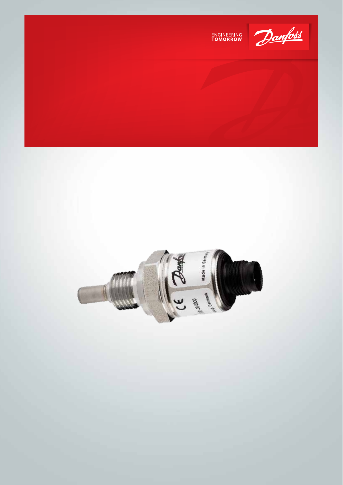
Temperature transmitter
CAN SAE J1939
DST T92C
ia.danfoss.com
Page 2

Operation guide | DST T92C Temperature transmitter CAN SAE J1939
Table of contents
1. General Information
Contents
1. General information................................................................................................................................... 2
1.1 Contact........................................................................................................................................................... 2
1.2 General............................................................................................................................................................ 2
1.3 CAN Interface................................................................................................................................................ 3
2. Specifications............................................................................................................................................... 3
3. J1939 communication.............................................................................................................................. 3
3.1 Introduction................................................................................................................................................. 3
3.2 Supported PGN’s and SPN’s.................................................................................................................... 4
3.3 Definitions..................................................................................................................................................... 9
3.3.1 PGN.................................................................................................................................................................. 9
3.3.2 SPN.................................................................................................................................................................. 9
3.4 Overview of the slot for pressure sensors......................................................................................... 10
3.5 References.................................................................................................................................................... 10
1.1 Contact
Danfoss A/S
Industrial Automation
DK-6430 Nordborg
Denmark
www.ia.danfoss.com
E-mail: technical support_IA@danfoss.com
1.2 General
The temperature transmitter DST T92C measures
the physical quantity temperature. The range is
-40 – 150 °C for the medium. The measured value
is transmitted on the CAN-Bus with the J1939
protocol. The transmitter takes 107 samples per
second, does filtering and converts the raw value
into the output format.
The CAN 2.0B interface is able to run up to a
speed of 1 Mbit/sec.
The device supports Diagnostic Message 1 (DM1,
PGN 0xFECA, active diagnostic trouble codes,
automatically send every second), Diagnostic
Message 2 (DM2, PGN 0xFECB, previously
active diagnostic trouble codes) and Diagnostic
Message 3 (DM3, PGN 0xFECC, diagnostic data
clear/reset for previously active DTCs). Also the
DST T92C CAN SAE J1939 firmware supports
static node addressing as well as dynamically
address claiming.
1.3 CAN Interface
The device includes a Full CAN controller
specified to CAN 2.0B. The physical layer of
the 2-wire interface is specified according to
ISO 11898. The wires are protected against
short-circuit. By adjusting the rise and fall
times of the CAN signals, the noise emission is
minimized to meet the EMC requirements. The
bus termination resistor is not included in the
device.
2 | © Danfoss | DCS (im) | 2018.01
Furthermore the device can easily configured
with a configuration vector (PGN 0xEF00) by
the customer if needed. An example dbc-file
with a default configuration to use with “Vector
CANdb++ Editor” is available on request.
IC.PS.P30.B1.02 | 520B8401
Page 3
Operation guide | DST T92C Temperature transmitter CAN SAE J1939
2. Specifications
Electrical specifications
Supply voltage 9 – 36 V DC protected against reverse polarity
Current consumption at U
= 24 V DC I < 50 mA typical, I
S
< 100 mA
MAX
CAN Interface
Physical layer
2-wire interface, 5 V level according to ISO 11898
Protected against short-circuit
Bit rate 250 kBit/s (max. 1 Mbit/sec prossible)
Signal rise time
Bit rate < 125 kbit/s 12 V/µs (without bus)
Bit rate ≥ 125 kbit/s > 24 V/µs (without bus)
Bus termination External
Protocol SAE J1939
Environment
EMC EN 61326-1:2013
Operating temperature -40 – 125 °C
Media temperature -40 – 150 °C
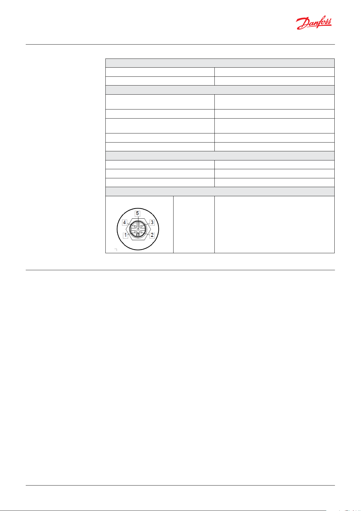
M12 connector Pin Assignment (CiA DR303-1)
Pin 1
Pin 2
Pin 3
Pin 4
Pin 5
CAN shield, PE
+U
, +24 V DC
B
GND, 0 V
CAN_H, CAN+
CAN_L, CAN-
3. J1939 Communication
3.1 Introduction
The Society of Automotive Engineers (SAE)
developed the 1939 standard to be the
preferred CAN for equipment used in industries
ranging from agriculture, construction, and fire/
rescue to forestry, materials handling as well as
on and off-highway vehicles. It is a high-level
protocol that defines how communication
between nodes (modules) occurs on the bus.
The 1939 network is a specific communication
system, supporting specific sets of applications
and a specific industry, rather than being
generalized.
Any electronic control unit (ECU) using J1939
is permitted to transmit a message on the
network when the bus is idle. Every message
includes a 29-bit identifier, which defines the
message priority, what data is contained within
the 8-byte data array that follows the identifier,
and which ECU sent the message.
© Danfoss | DCS (im) | 2018.01
IC.PS.P30.B1.02 | 520B8401 3
Page 4

Operation guide | DST T92C Temperature transmitter CAN SAE J1939
3.2 Supported PGN’s and SPN’s
PGN’s of SAE J1939
PGN SPN TTR [ms]
61495 6313 100 2 SAEtp01 Engine Turbocharger Compressor Blowoff Actuator 1 Temperature
61649 7090 100 2 SAEtp01 Engine Cylinder Head Bypass Actuator 1 Temperature
64548 7574 1000 2 SAEtp01 Aftertreatment 2 Diesel Exhaust Fluid Tank Temperature 2
64549 7572 1000 2 SAEtp01 Aftertreatment 1 Diesel Exhaust Fluid Tank Temperature 2
64550 7529 1000 1 SAEtp01 Aftertreatment 2 Diesel Exhaust Fluid Controller Temperature
64550 7535 1000 2 SAEtp01 Aftertreatment 2 Diesel Exhaust Fluid Controller 2 Temperature
64551 5480 1000 1 SAEtp01 Aftertreatment 1 Diesel Exhaust Fluid Controller 1 Temperature
64551 7528 1000 2 SAEtp01 Aftertreatment 1 Diesel Exhaust Fluid Controller 2 Temperature
64557 7514 500 5 SAEtp01 Engine Fuel 2 Injector Metering Rail 1 Temperature 2
64571 7059 1000 1 SAEtp01 Engine End Bearing 17 Temperature
64571 7060 1000 2 SAEtp01 Engine End Bearing 18 Temperature
64571 7061 1000 3 SAEtp01 Engine End Bearing 19 Temperature
64571 7062 1000 4 SAEtp01 Engine End Bearing 20 Temperature
64572 7051 1000 1 SAEtp01 Engine End Bearing 9 Temperature
64572 7052 1000 2 SAEtp01 Engine End Bearing 10 Temperature
64572 7053 1000 3 SAEtp01 Engine End Bearing 11 Temperature
64572 7054 1000 4 SAEtp01 Engine End Bearing 12 Temperature
64572 7055 1000 5 SAEtp01 Engine End Bearing 13 Temperature
64572 7056 1000 6 SAEtp01 Engine End Bearing 14 Temperature
64572 7057 1000 7 SAEtp01 Engine End Bearing 15 Temperature
64572 7058 1000 8 SAEtp01 Engine End Bearing 16 Temperature
64573 7043 1000 1 SAEtp01 Engine End Bearing 1 Temperature
64573 7044 1000 2 SAEtp01 Engine End Bearing 2 Temperature
64573 7045 1000 3 SAEtp01 Engine End Bearing 3 Temperature
64573 7046 1000 4 SAEtp01 Engine End Bearing 4 Temperature
64573 7047 1000 5 SAEtp01 Engine End Bearing 5 Temperature
64573 7048 1000 6 SAEtp01 Engine End Bearing 6 Temperature
Data
Position
Slot SPN Name
64573 7049 1000 7 SAEtp01 Engine End Bearing 7 Temperature
64573 7050 1000 8 SAEtp01 Engine End Bearing 8 Temperature
64577 7023 500 5 SAEtp01 Engine Fuel 2 Injector Metering Rail 1 Temperature
64577 7024 500 6 SAEtp01 Engine Fuel 2 Injector Metering Rail 2 Temperature
64579 6984 On request 7 SAEtp01 O ver Temperature
64590 7460 500 3 SAEtp01 Aftertreatment 1 Diesel Exhaust Fluid Doser 2 Temperature
64651 6780 200 3-4 SAEtp01 Aftertreatment 1 Particulate Sensor Temperature
64655 6610 100 2 SAEtp01 Engine Fuel Vaporizer 1 Discharge Temperature
64655 6815 100 3 SAEtp01 Gaseous Fuel Accumulator Temperature
64689 6214 100 1 SAEtp01 Engine Ignition Control Module 1 Temperature
64689 6215 100 2 SAEtp01 Engine Ignition Control Module 2 Temperature
64705 5938 1000 2 SAEtp01 Transmission Oil Transmission Cooler Outlet Temperature
64708 5864 500 1-2 SAEtp01 Aftertreatment 2 SCR <intermediate Temperature
64709 5862 500 1-2 SAEtp01 Aftertreatment 1 SCR <intermediate Temperature
64713 6783 100 1 SAEtp01 Engine Throttle Valve 1 Temperature
64713 5784 100 2 SAEtp01 Engine Throttle Valve 2 Temperature
64713 5785 100 3 SAEtp01 Engine Fuel Valve 1 Temperature
4 | © Danfoss | DCS (im) | 2018.01
IC.PS.P30.B1.02 | 520B8401
Page 5

Operation guide | DST T92C Temperature transmitter CAN SAE J1939
PGN SPN TTR [ms]
64713 5786 100 4 SAEtp01 Engine Fuel Valve 2 Temperature
64713 5787 100 5 SAEtp01 Engine Turbocharger Wastegate Actuator 2 Temperature
64713 7314 100 6 SAEtp01 Engine Fuel Rack Supply Temperature
64714 5775 100 2 SAEtp01 Engine Exhaust Gas Recirculation 2 Actuator 1 Temperature
64714 5779 100 5 SAEtp01 Engine Exhaust Gas Recirculation 2 Actuator 2 Temperature
64715 5765 100 2 SAEtp01 Engine Exhaust Gas Recirculation 1 Actuator 1 Temperature
64715 5769 100 5 SAEtp01 Engine Exhaust Gas Recirculation 1 Actuator 2 Temperature
64736 5501 100 1-2 SAEtp02 Aftertreatment 1 Diesel Particulate Filter Intake Temperature Set Point
64738 5561 1000 3 SAEtp01 Supplement Fan Controller ECU Temperature
64740 5540 30000 7-8 SAEtp02 Engine Fuel Temperature (High Resolution)
64741 5536 30000 7-8 SAEtp02 Hydraulic Oil Temperature (High Resolution)
64749 5315 500 1-2 SAEtp02 Aftertreatment 2 Warm Up Diesel Oxidation Catalyst Intake Temperature
64749 5316 500 3-4 SAEtp02 Aftertreatment 2 Warm Up Diesel Oxidation Catalys Outlet Temperature
64753 5788 100 6 SAEtp01 Engine Turbocharger Wastegate Actuator 1 Temperature
64753 5790 100 8 SAEtp01 Engine Exhaust Pressure Actuator 1 Temperature
64755 5791 100 5 SAEtp01 Engine Turbocharger Compressor Bypass Actuator 1 Temperature
64755 5792 100 6 SAEtp01 Engine Turbocharger Compressor Bypass Actuator 2 Temperature
64756 5289 1000 1-2 SAEtp02 Engine Charge Air Cooler 2 Intake Temperature
64756 5290 1000 3-4 SAEtp02 Engine Charge Air Cooler 2 Outlet Temperature
64756 5291 1000 5-6 SAEtp02 Engine Charge Air Cooler 2 Ambient Air Temperature
64757 5286 1000 1-2 SAEtp02 Engine Charge Air Cooler 2 Precooler Intake Temperature
64757 5287 1000 3-4 SAEtp02 Engine Charge Air Cooler 2 Precooler Outlet Temperature
64758 5283 1000 1-2 SAEtp02 Engine Charge Air Cooler 1 Intake Temperature
64758 5284 1000 3-4 SAEtp02 Engine Charge Air Cooler 1 Ambient Air Temperature
64759 5280 1000 1-2 SAEtp02 Engine Charge Air Cooler 1 Precooler Intake Temperature
64759 5281 1000 3-4 SAEtp02 Engine Charge Air Cooler 1 Precooler Outlet Temperature
64766 5258 On request 1-2 SAEtp02 Engine Exhaust Gas Recirculation 2 Cooler Intake Temperature
64767 5255 1000 1-2 SAEtp02 Engine Exhaust Gas Recirculation 2 Temperature
64767 5256 1000 3-4 SAEtp02 Engine Exhaust Gas Recirculation 2 Mixer Intake Temperature
64769 5148 500 4 SAEtp01 Low Voltage Disconnect Temperature
64776 5925 30000 7-8 SAEtp02 Engine Oil Temperature 3
64794 4809 500 1-2 SAEtp02 Aftertreatment 1 Warm Up Diesel Oxidation Catalyst Intake Temperature
64794 4810 500 3-4 SAEtp02 Aftertreatment 1 Warm Up Diesel Oxidation Catalyst Outlet Temperature
64795 5570 1000 8 SAEtp01 Diesel Particulate Filter 2 Soot Sensor ECU Internal Temperature
64796 5569 1000 8 SAEtp01 Diesel Particulate Filter 1 Soot Sensor ECU Internal Temperature
64797 4779 On request 1-2 SAEtp02 Aftertreament 1 Three Way Catalyst Differential Temperature
64797 4780 On request 3-4 SAEtp02 Aftertreatment 2 Three Way Catalyst Differential Temperature
64798 4777 On request 1-2 SAEtp02 Aftertreatment 1 Gas Oxidation Catalyst Differential Temperature
64798 4778 On request 3-4 SAEtp02 Aftertreatment 2 Gas Oxidation Catalyst Differential Temperature
64799 4771 500 1-2 SAEtp02 Aftertreatment 2 Diesel Oxidation Catalyst Intake Temperature
64799 4772 500 3-4 SAEtp02 Aftertreatment 2 Diesel Oxidation Catalyst Outlet Temperature
64800 4765 500 1-2 SAEtp02 Aftertreatment 1 Diesel Oxidation Catalyst Intake Temperature
64800 4766 500 3-4 SAEtp02 Aftertreatment 1 Diesel Oxidation Catalyst Outlet Temperature
64801 4759 500 1-2 SAEtp02 Aftertreatment 2 Gas Oxidation Catalyst Intake Temperature
64801 4760 500 3-4 SAEtp02 Aftertreatment 2 Gas Oxidation Catalyst Outlet Temperature
64802 4753 500 1-2 SAEtp02 Aftertreatment 1 Gas Oxidation Catalyst Intake Temperature
64802 4754 500 3-4 SAEtp02 Aftertreatment 1 Gas Oxidation Catalyst Outlet Temperature
64820 4434 1000 2 SAEtp01 Aftertreatment 2 Diesel Exhaust Fluid Quick Thaw Temperature
Data
Position
Slot SPN Name
© Danfoss | DCS (im) | 2018.01
IC.PS.P30.B1.02 | 520B8401 5
Page 6

Operation guide | DST T92C Temperature transmitter CAN SAE J1939
PGN SPN TTR [ms]
64821 4427 1000 2 SAEtp01 Aftertreatment 2 Diesel Exhaust Fluid Tank Temperature
64822 4420 1000 1 SAEtp01 Aftertreatment 2 Diesel Exhaust Fluid Temperature 2
64824 4413 500 1-2 SAEtp02 Aftertreatment 2 SCR Intake Temperature
64824 4415 500 4-5 SAEtp02 Aftertreatment 2 SCR Outlet Temperature
64827 4390 500 3 SAEtp01 Aftertreatment 2 Diesel Exhaust Fluid Doser 1 Temperature
64829 4368 1000 2 SAEtp01 Aftertreatment 1 Diesel Exhaust Fluid Quick Thaw Temperature
64830 4360 500 1-2 SAEtp02 Aftertreatment 1 SCR Intake Temperature
64830 4363 500 4-5 SAEtp02 Aftertreatment 1 SCR Outlet Temperature
64831 4337 500 3 SAEtp01 Aftertreatment 1 Diesel Exhaust Fluid Doser 1 Temperature
64837 4295 500 1-2 SAEtp02 Aftertreatment 2 Three Way Catalyst Intake Temperature
64837 4296 500 3-4 SAEtp02 Aftertreatment 2 Three Way Catalyst Outlet Temperature
64838 4289 500 1-2 SAEtp02 Aftertreatment 1 Three Way Catalyst Intake Temperature
64838 4290 500 3-4 SAEtp02 Aftertreatment 1 Three Way Catalyst Outlet Temperature
64849 4199 1000 2 SAEtp01 Desired Aftercooler Coolant Intake Temperature
64850 4196 1000 2 SAEtp01 Desired Engine Coolant Pump Outlet Temperature
64851 4151 500 1-2 SAEtp02 Engine Exhaust Bank Temperature Average
64851 4153 500 3-4 SAEtp02 Engine Exhaust Bank 1 Temperature Average
64851 4152 500 5-6 SAEtp02 Engine Exhaust Bank 2 Temperature Average
64869 5456 500 6 SAEtp01 Aftertreatment 1 Hydrocarbon Doser Intake Fuel Temperature
64870 4076 1000 1 SAEtp01 Engine Coolant Tempera5ture 2
64870 4193 1000 2 SAEtp01 Engine Coolant Pump Outlet Temperature
64870 4288 1000 4-5 SAEtp02 Engine Exhaust Valve Actuation System Oil Temperature
64870 5020 1000 5-7 SAEtp02 Engine Exhaust Gas Recirculation 1 Mixer Intake Temperature
64870 6209 1000 8 SAEtp01 Engine Coolant Temperature 3
64876 3834 500 3-4 SAEtp02 Aftertreatment 2 Secondary Air Temperature
64877 3831 500 3-4 SAEtp02 Aftertreatment 1 Secondary Air Temperature
64879 4750 On request 3-4 SAEtp02 Engine Exhaust Gas Recirculation 1 Cooler Intake Temperature
64917 3823 1000 2-3 SAEtp02 Transmission Torque Converter Oil Outlet Temperature
64917 5913 1000 5-6 SAEtp02 Transmission Oil Temperature 2
64919 2775 1000 1 SAEtp01 Engine Fuel Supply Temperature
64919 2776 1000 2 SAEtp01 Engine Fuel Return Temperature
64923 3515 1000 1 SAEtp01 Aftertreatmwent 1 Diesel Exhaust Fluid Temperature 2
63930 3468 500 5 SAEtp01 Engine Fuel Temperature 2
64943 3283 500 1-2 SAEtp02 Aftertreatment 2 Exhaust Temperature 2
64943 3284 500 3-4 SAEtp02 Aftertreatment 2 Diesel Particulate Filter Intermediate Temperature
64944 3279 500 1-2 SAEtp02 Aftertreatment 2 Exhaust Temperature 3
64944 3280 500 3-4 SAEtp02 Aftertreatment 2 Diesel Particulate Filter Outlet Temperature
64945 3275 500 1-2 SAEtp02 Aftertreatment 2 Exhaust Temperature 1
64945 3276 500 3-4 SAEtp02 Aftertreatment 2 Diesel Particulate Filter Intake Temperature
64946 3249 500 1-2 SAEtp02 Aftertreatment 1 Exhaust Temperature 2
64946 3250 500 3-4 SAEtp02 Aftertreatment 1 Diesel Particulate Filter Intermediate Temperature
64947 3245 500 1-2 SAEtp02 Aftertreatment 1 Exhaust Remperature 3
64947 3246 500 3-4 SAEtp02 Aftertreatment 1 Diesel Particulate Filter Outlet Temperature
64948 3241 500 1-2 SAEtp02 Aftertreatment 1 Exhaust Temperature 1
64948 3242 500 3-4 SAEtp02 Aftertreatment 1 Diesel Particulate Filter Intake Temperature
64979 2916 1000 1-2 SAEtp02 Engine Turbocharger 1 Compressor outlet Temperature
64979 2799 1000 3-4 SAEtp02 Engine Turbocharger 2 Compressor Outlet Temperature
64979 2800 1000 5-6 SAEtp02 Engine Turbocharger 3 Compressor Outlet Temperature
Data
Position
Slot SPN Name
6 | © Danfoss | DCS (im) | 2018.01
IC.PS.P30.B1.02 | 520B8401
Page 7

Operation guide | DST T92C Temperature transmitter CAN SAE J1939
PGN SPN TTR [ms]
64979 2801 1000 7-8 SAEtp02 Engine Turbocharger 4 Compressor Outlet Temperature
64981 2789 On request 1-2 SAEtp02 Engine Turbocharger 1 Calculated Turbine Intake Temperature
64981 2790 On reuest 3-4 SAEtp02 Engine Turbocharger 1 Calculated Turbine Outlet Temperature
64992 5581 1000 5-6 SAEtp02 Calculated Ambient Air Temperature
65031 2433 500 1-2 SAEtp02 Engine Exhaust Manifold Bank 2 Temperature 1
65031 2434 500 3-4 SAEtp02 Engine Exhaust Manifold Bank 1 Temperature 1
65031 5969 500 5-6 SAEtp02 Engine Exhaust Manifold Bank 2 Temperature 2
65031 5970 500 7-8 SAEtp02 Engine Exhaust Manifold Bank 1 Temperature 2
65104 1800 1000 1 SAEtp01 SLI Battery 1 Temperature
65104 1801 1000 2 SAEtp01 SLI Battery 2 Temperature
65104 2779 1000 3 SAEtp01 SLI Battery 3 Temperature
65104 2780 1000 4 SAEtp01 SLI Battery 4 Temperature
65110 3031 1000 2 SAEtp01 Aftertreatment 1 Diesel Exhaust Fluid Tank Temperature
65128 1638 1000 1 SAEtp01 Hydraulic Temperature
65129 1636 1000 1-2 SAEtp02 Engine Intake Mainfold 1 Temperature (High Resolution)
65129 1637 1000 3-4 SAEtp02 Engine Coolant Temperature (High Resolution)
65129 2986 1000 5-6 SAEtp02 Engine Intake Valve Actuation System Oil Temperature
65129 2630 1000 7-8 SAEtp02 Engine Charge Air Cooler 1 outlet Temperature
65133 1687 1000 1 SAEtp01 Auxiliary Heater Output Coolant Temperature
65133 1688 1000 2 SAEtp01 Auxiliary Heater Input Air Temperature
65164 441 On request 1 SAEtp01 Auxiliary Temperature 1
65164 442 On request 2 SAEtp01 Auxiliary Temperature 2
65172 1212 500 2 SAEtp01 Engine Auxiliary Coolant Temperature
65175 1184 1000 1-2 SAEtp02 Engine Turbocharger 1 Turbine Outlet Temperature
65175 1185 1000 3-4 SAEtp02 Engine Turbocharger 2 Turbine Outlet Temperature
65175 1186 1000 5-6 SAEtp02 Engine Turbocharger 3 Turbine Outlet Temperature
65175 1187 1000 7-8 SAEtp02 Engine Turbocharger 4 Turbine Outlet Temperature
65176 1180 1000 1-2 SAEtp02 Engine Turbocharger 1 Turbine Intake Temperature
65176 1181 1000 3-4 SAEtp02 Engine Turbocharger 2 Turbine Intake Temperature
65176 1182 1000 5-6 SAEtp02 Engine Turbocharger 3 Turbine Intake Temperature
65176 1183 1000 7-8 SAEtp02 Engine Turbocharger 4 Turbine Intake Temperature
65178 1172 1000 1-2 SAEtp02 Engine Turbocharger 1 Compressor Intake Temperature
65178 1173 1000 3-4 SAEtp02 Engine Turbocharger 2 Compressor Intake Temperature
65178 1174 1000 5-5 SAEtp02 Engine Turbocharger 3 Compressor Intake Temperature
65178 1175 1000 7-8 SAEtp02 Engine Turbocharger 4 Compressor Intake Temperature
65180 1165 1000 1-2 SAEtp02 Engine Main Bearing 9 Temperature
65180 1166 1000 3-4 SAEtp02 Engine Main Bearing 10 Temperature
65180 1167 1000 5-6 SAEtp02 Engine Main Bearing 11 Temperature
65180 6830 1000 7-8 SAEtp02 Engine Main Bearing 12 Temperature
65181 1161 1000 1-2 SAEtp02 Engine Main Bearing 5 Temperature
65181 1162 1000 3-4 SAEtp02 Engine Main Bearing 6 Temperature
65181 1163 1000 5-6 SAEtp02 Engine Main Bearing 7 Temperature
65181 1164 1000 7-8 SAEtp02 Engine Main Bearing 8 Temperature
65182 1157 1000 1-2 SAEtp02 Engine Main Bearing 1 Temperature
65182 1158 1000 3-4 SAEtp02 Engine Main Bearing 2 Temperature
65182 1159 1000 5-6 SAEtp02 Engine Main Bearing 3 Temperature
65182 1160 1000 7-8 SAEtp02 Engine Main Bearing 4 Temperature
65183 1153 1000 1-2 SAEtp02 Engine Exhaust Gas Port 17 Tempeature
Data
Position
Slot SPN Name
© Danfoss | DCS (im) | 2018.01
IC.PS.P30.B1.02 | 520B8401 7
Page 8

Operation guide | DST T92C Temperature transmitter CAN SAE J1939
PGN SPN TTR [ms]
65183 1154 1000 3-4 SAEtp02 Engine Exhaust Gas Port 18 Temperature
65183 1155 1000 5-6 SAEtp02 Engine Exhaust Gas Port 19 Temperature
65183 1156 1000 7-2 SAEtp02 Engine Exhaust Gas Port 20 Temperature
65184 1149 1000 1-2 SAEtp02 Engine Exhaust Gas Port 13 Temperature
65184 1150 1000 3-4 SAEtp02 Engine Exhaust Gas Port 14 Temperature
65184 1151 1000 5-6 SAEtp02 Engine Exhaust Gas Port 15 Temperature
65184 1152 1000 7-8 SAEtp02 Engine Exhaust Gas Port 16 Temperature
65185 1145 1000 1-2 SAEtp02 Engine Exhaust Gas Port 9 Temperature
65185 1146 1000 3-4 SAEtp02 Engine Exhaust Gas Port 10 Temperature
65185 1147 1000 5-6 SAEtp02 Engine Exhaust Gas Port 11 Temperature
65185 1148 1000 7-8 SAEtp02 Engine Exhaust Gas Port 12 Temperature
65186 1141 1000 1-2 SAEtp02 Engine Exhaust Gas Port 5 Temperature
65186 1142 1000 3-4 SAEtp02 Engine Exhaust Gas Port 6 Temperature
65186 1143 1000 5-6 SAEtp02 Engine Exhaust Gas Port 7 Temperature
65186 1144 1000 7-8 SAEtp02 Engine Exhaust Gas Port 8 Temperature
65187 1137 1000 1-2 SAEtp02 Engine Exhaust Gas Port 1 Temperature
65187 1138 1000 3-4 SAEtp02 Engine Exhaust Gas Port 2 Temperature
65187 1139 1000 5-6 SAEtp02 Engine Exhaust Gas Port 3 Temperature
65187 1140 1000 7-8 SAEtp02 Engine Exhaust Gas Port 4 Temperature
65188 1135 1000 1-2 SAEtp02 Engine Oil Temperature 2
65188 1136 1000 3-4 SAEtp02 Engine ECU Temperature
65188 412 1000 7-8 SAEtp02 Engine Exhaust Gas Recirculation 1 Temperature
65189 1131 1000 1 SAEtp01 Engine Intake Manifold 2 Temperature
65189 1132 1000 2 SAEtp01 Engine Intake Manifold 3 Temperature
65189 1133 1000 3 SAEtp01 Engine Intake Manifold 4 Temperature
65189 1802 1000 4 SAEtp01 Engine Intake Manifold 5 Temperature
65189 1803 1000 5 SAEtp01 Engine Intake Manifold 6 Temperature
65191 1122 1000 1 SAEtp01 Engine Alternator Bearing 1 Temperature
65191 1123 1000 2 SAEtp01 Engine Alternator Bearing 2 Temperature
65191 1124 1000 3 SAEtp01 Engine Alternator Winding 1 Temperature
65191 1125 1000 4 SAEtp01 Engine Alternator Winding 2 Temperature
65191 1126 1000 5 SAEtp01 Engine Alternator Winding 3 Temperature
65262 110 1000 1 SAEtp01 Engine Coolant Temperature
65262 174 1000 2 SAEtp01 Engine Fuel Temperature 1
65262 175 1000 3-4 SAEtp02 Engine Oil Temperature 1
65262 176 1000 5-6 SAEtp02 Engine Turbocharger Oil Temperature
65262 52 1000 SAEtp01 Engine Intercooler Temperature
65264 90 100 1 SAEtp01 Power Takeoff Oil Temperature
65268 242 10000 3-4 SAEtp02 Tire Temperature
65269 170 1000 2-3 SAEtp02 Cab Interior Temperature
65269 171 1000 4-5 SAEtp02 Ambient Air Temperature
65269 172 1000 6 SAEtp01 Engine Intake Air Temperature
65269 79 1000 7-8 SAEtp02 Road Surface Temperature
65270 105 500 3 SAEtp01 Engine Intake Manifold 1 Temperature
65270 173 500 6-7 SAEtp02 Engine Exhaust Temperature
65272 177 1000 5-6 SAEtp02 Transmission Oil Temperature 1
65273 75 1000 1 SAEtp01 Steering Axle Temperature
65273 578 1000 4 SAEtp01 Drive Axle Temperature
Data
Position
Slot SPN Name
8 | © Danfoss | DCS (im) | 2018.01
IC.PS.P30.B1.02 | 520B8401
Page 9

Operation guide | DST T92C Temperature transmitter CAN SAE J1939
PGN SPN TTR [ms]
65275 120 1000 2 SAEtp01 Hydraulic Retarder Oil Temperature
65275 5656 1000 4 SAEtp01 Retarder Coolant Outlet Temperature
65276 169 1000 5-6 SAEtp02 argo Ambient Temperature
65277 7020 500 6 SAEtp01 LNG Vaporizer Coolant Outlet Temperature
Data
Position
Slot SPN Name
3.3 Definitions 3.3.1 PGN
The PGN (Parameter Group Number) uniquely
identifies the Parameter Group (PG) that
is being transmitted in the message. The
Parameter Group Number (PGN) is a part of the
29-bit identifier sent with every message.
3.3.2 SPN
Each parameter used in the J1939 network is
described by the standard. A Suspect Parameter
Number (SPN) is a number that has been assigned
by SAE committee to a specific parameter. Each
SPN has the following detailed information
associated with it: data length (in bytes);
data type; resolution, offset; range; and a tag
(label) for reference. SPNs that share common
characteristics will be grouped into a Parameter
Group (PG) and will be transmitted to the network
using the same PGN.
3.4 Overview of the slots for temperature
sensors
Slot
Name
Slot Type Scaling Range Offset Length
SAEtp01 Temperature 1 °C/bit -40 – 210 °C -40 °Ca 1 byte
SAEpr02 Temperature 0.03125 °C/bit -273 – 1734.96875 °C -273 °C 2 bytes
SAEtp04 Temperature 1/128 °C/bit -2373 – 228.9921875 °C -273 °C 2 bytes
SLOT is the acronym for Scaling, Limit, Offset and
Transfer function. The following SAE SLOTs are
supported by the device.
Additionally, the scaling, limit and offset can be
completely free configured by using a customer
specific PGN. Only the data length is limited to 1,
2 or 4 bytes.
For example, a default Danfoss-specific SLOT was
defined, which perfectly fits the complete
DST T92C CAN media temperature operational
range:
Slot Name Slot Type Scaling Range Offset Length
Danfosstp01 Temperature 0.003 °C/bit -40 – 150 °C -40 °Ca 2 bytes
3.5 References
© Danfoss | DCS (im) | 2018.01
ISO11783-3 Data Link Layer
J1939-71
IC.PS.P30.B1.02 | 520B8401 9
Page 10

Operation guide | DST T92C Temperature transmitter CAN SAE J1939
10 | © Danfoss | DCS (im) | 2018.01
IC.PS.P30.B1.02 | 520B8401
Page 11

Operation guide | DST T92C Temperature transmitter CAN SAE J1939
© Danfoss | DCS (im) | 2018.01
IC.PS.P30.B1.02 | 520B8401 11
Page 12

Danfoss A/S
Industrial Automation
Nordborgvej 81
DK-6430 Nordborg
Denmark
www.ia.danfoss.com
© Danfoss | DCS (im) | 2018.01
IC.PS.P30.B1.02 | 520B9401 | 12
 Loading...