

Page 1

Safety guide
Pressure transmitter SIL-2
DST P92S
ia.danfoss.com
Page 2

Safety guide | DST P92S Pressure transmitter
Table of contents
Contents
1. Introduction ................................................................................................................................................. 2
2. General information.................................................................................................................................. 3
2.1 Contact........................................................................................................................................................... 3
2.2 Used symbols and format........................................................................................................................ 3
2.3 Reference....................................................................................................................................................... 3
2.4 Abbreviations............................................................................................................................................... 4
3. Qualication test........................................................................................................................................ 5
3.1 Compliance information......................................................................................................................... 5
3.2 Electromagnetic and electrical tests................................................................................................... 5
3.3 Environmental qualication................................................................................................................... 12
4. System information................................................................................................................................... 13
4.1 Functional safety classication............................................................................................................. 13
4.2 Technical data............................................................................................................................................. 14
4.3 Technical drawings..................................................................................................................................... 16
4.4 Pin congurations...................................................................................................................................... 17
4.5 Wiring diagram............................................................................................................................................ 17
4.6 Safety functions.......................................................................................................................................... 17
4.7 Diagnosis....................................................................................................................................................... 18
5. Safety requirements.................................................................................................................................. 18
5.1 Known issues............................................................................................................................................... 19
5.2 Instructions and constraints................................................................................................................... 19
5.3 Safe state....................................................................................................................................................... 19
5.4 System............................................................................................................................................................ 20
5.5 Pressure.......................................................................................................................................................... 21
5.6 Outputs.......................................................................................................................................................... 22
5.7 Decommissioning and disposal............................................................................................................ 24
5.8 Security.......................................................................................................................................................... 24
6. Transport and storage............................................................................................................................... 24
7. Maintenance................................................................................................................................................. 24
8. Mounting....................................................................................................................................................... 24
9. Dismounting................................................................................................................................................. 25
1. Introduction This document includes system information and
safety requirements for the pressure transmitter
DST P92S, which have to be considered and
fullled within the overall safety application.
It shall be used as input for the:
• development of the overall safety
application.
• overall installation and commissioning
planning.
• overall safety validation planning.
• overall operation, maintenance and repair
planning.
2 | © Danfoss | DCS (im) | 2020.01
IC.PS.P21.2A.02 | 520B7782
Page 3

Safety guide | DST P92S Pressure transmitter
2. General information
2.1 Contact
Danfoss A/S
Industrial Automation
DK-6430 Nordborg
Denmark
www.ia.danfoss.com
E-mail: technical support_IA@danfoss.com
2.2 Used symbols and formats
REQIREMENT:
Requirement which shall be adhered
to maintain safe system operations.
RECOMMENDATION:
Recommendation on how to handle
certain aspects of requirements.
WARNING:
Warning of faults and errors during
the application development.
NOTE:
A note provides additional and
important information of the system
behavior.
2.3 Reference
No. Description
International standard IEC 61508:2010
/1/
Functional safety of electrical, electronic and programmable electronic safety-related systems
Safety standard EN ISO 13849-1:2015
/2/
Safety of machinery - Safety-related parts of control systems
/3/ Siemens standard SN 29500: Failure rates of components
EMC standard EN 61000-4-5:2005
/4/
Electromagnetic Compatibility; testing and measurement techniques - Surge immunity test
Safety standard ISO 25119:2010 / EN 16590:2014
/5/
Tractors and machinery for agriculture and forestry - Safety-related parts of constrol system
© Danfoss | DCS (im) | 2020.01
IC.PS.P21.2A.02 | 520B7782 | 3
Page 4

Safety guide | DST P92S Pressure transmitter
2.4 Abbreviations
Abbreviation Description
AgPL Agricultural Performance Level: Safety classication according to ISO 25119 / EN 16590
CCF Common Cause Failure
CRC Cyclic Redundancy Check
DC Diagnostic Coverage
DFB Digital Feedback
DTI Diagnostic Test Interval
ECU Electronic Control Unit
EEPROM Electrically Erasable Programmable ROM
EMC Electromagnetic Compatibility
FRT Fault Reaction Time
FTT Fault Tolerance Time
FS Full Scale
GND Ground
HW Hardware
I/O Input / Output
MDT Mean Downtime
MTBF Mean Time Between Failure
MTTFd Mean Time To dangerous Failure
MTTR Mean Time To Restoration
PFH Probability of dangerous Failure per Hour
PL Performance Level: Safety classication according to EN ISO 13849
PST Process Safety Time
RAM Random Access Memory
ROM Read Only Memory
SFF Safe Failure Fraction
SIL Safety Integrity Level: Safety classication according to IEC 61508
SMM Shadow Memory Module (if existing)
SN Siemens Standard
SRL Software Requirement Level
SW Software
TBD To be determined / to be dened
VCC Positive voltage supply connection
VFB Voltage Feedback
VSRC Valid Safety Relevant Conguration
4 | © Danfoss | DCS (im) | 2020.01
IC.PS.P21.2A.02 | 520B7782
Page 5

Safety guide | DST P92S Pressure transmitter
3. Qualication tests
3.1 Compliance information
Standard Description Parameter
Conformity See EU Dclaration of conformity
Certication
Requirement in accordance
to the EC type-approval of
the Kraftfahrt-Bundesamt
KBA (KraftfahrtBundesamt)
See also Functional Safety Classication on page 9
E
(KBA) - Fedral Motor tTransport
1
Authority:
All vehicle types with a 12 V
respectively 24 V - electrical
wiring and battery(-) at the
body
According UN ECE Regulation No. 10
3.2 Electromagnetic and electrical tests
Electrical Safety
Standard Test description Test parameter
Danfoss reference Supply voltage Current variant:
Operation with U
and U
= 9V DC for a duration of
min
= 32V DC
max
60 min. each.
Current
variant
x x
Ratiometric
voltage
variant
Ratiometric voltage variant:
Operation withg U
and U
= 4.5V DC for a duration
min
= 5.5 V DC
max
of 50 min. each
Danfoss reference Starting prole
switch-on
hysteresis
Overvoltage and hysteresis:
U
t = U
max
+3%
Tes
t = 5 min.
Undervoltage and hysteresis:
U
= U
Start
nom
ΔU = 0.1V
U
= U
min
switch-o
Danfoss reference Broken cable
supply lines
t at U
Interruption of supply lines:
Current variant:
U
max
U
min
switch-on
= 32V
= 9V
= 5 min.
Ratiometric voltage variant:
U
= 5.5V
max
U
= 4.5V
min
t = 60 sec.
Danfoss reference Short circuits Output signals to VCC or GND in
each case
t = 60 sec.
Danfoss reference
ISO 16750-2:
2012-11
Polarity
Protection
Change supply polarity:
t = 5 min.
Curent variant:
No current limitation of supply
necessary
x x
x x
x x
x x
© Danfoss | DCS (im) | 2020.01
Ratiometric voltage variant:
Current limiting of supply to 2A
IC.PS.P21.2A.02 | 520B7782 | 5
Page 6

Safety guide | DST P92S Pressure transmitter
Standard Test description Test parameter
Danfoss reference Current
consumption
Supply current consumption
without load:
Current variant:
I
≤ 50 mA
max
Ratiometric voltage variant:
I
≤ 20 mA
max
Danfoss reference Load test 48 hours at minimum
temperature:
12 hours without operating, 36
hours with operating U
min
and l
min
48 hours at maximum
Danfoss reference
ISO 16750-2:
2012-11
Insulation
Resistance
temperature with operation U
and I
max
Unpowered; 500V DC; 60
sec.; 50% rh; 35 °C; between
Connector pins and electric
max
conductive housing without
galvanic contact.
Insulation resistance > 10 MΩ
CE Conformity (EMC)
Standard Test Description Test Parameter Current
variant
DIN EN 61000-6-3
DIN EN 61326
DIN 61326-2-3
DIN EN 610000-4-2:2009-12
DIN EN 61326-1
Emission
Electrostatic Discharge (ESD)
Conducted emission: 150 kHz to 30 MHz
Radiated emission: 30 MHz to 1 GHz
Direct discharge:
Contact discharge:
±2 kV, ±4 kV
Air discharge:
±2 kV, ±4 kV, ±8 k
Current
variant
x x
x x
x x
x x
x x
Ratiometric
voltage
variant
Ratiometric
voltage
variant
DIN EN 61000-4-2: 2009-12
DIN EN 61326-1 Electrostatic Discharge (ESD)
DIN EN 61000-4-2: 2009-12
DIN EN 61326-1 Electrostatic Discharge (ESD)
DIN EN 61000-4-3: 2011-04
DIN EN 61326-1
DIN EN 61326-2-3
DIN EN 61000-4-4: 2013-04
DIN EN 61326-1
DIN EN 61326-2-3
Immunity
Burst
6 | © Danfoss | DCS (im) | 2020.01
10 discarges per test point
Indirect discharge:
(horizontal coupling-plate)
Contact discharge: ±2 kV; ±4 kV
15 discharges per test point
Indirect discharge:
(vertical coupling-plate)
Contact discharge: ±2 kV; ±4 kV
15 discharges per test point
Immunity radio frequency:
80 MHz to 1 GHz (10 V/m)
1.4 GHz to 2.0 GHz (3 V/m)
2.0 GHz to 2.7 GHz (1 V/m)
3 m, horizontal and vertical
Test voltage:
Supply lines: ± 2 kV
Data lines: ±1 kV
Duration: 5 min.
Pulse form: 5/50 ns
Frequency: 5 kHz
Polarity: positive and negative
x x
x x
x x
x x
IC.PS.P21.2A.02 | 520B7782
Page 7

Safety guide | DST P92S Pressure transmitter
Standard Test Description Test Parameter Current
variant
Symmetrical coupling (L-N):
Supply lines: ±0.5 kV; ±1 kV
Coupling: 2 Ω / 18 µF
DIN EN 61000-4-5: 2007-06
DIN EN 61326-1
DIN 61326-2-3
DIN EN 610000-4-6: 2014
DIN EN 61326-1
DIN EN 61326-2-3
DIN EN 61000-4-8
DIN EN 61326-1
DIN EN 61326-2-3
DIN EN 61000-4-8
DIN EN 61326-3-1
DIN EN 61326-1
DIN EN 61326-2-3
Surge
Immunity
Power Frequency
Magnetic Fields
Power Frequency
Magnetic Fields
Unsymmetrical coupling (L-PE, N-PE, LN-PE):
Supply lines: ±0.5 kV; ±1 kV, ±2 kV
Signal lines: not required, cable length <30 m
Coupling: 12 Ω / 9 µF
Number of repeats: 5
Conducted disturbances
0.15 mHz – 80 MHz, 3 V, 80% AM sine wave 1 kHz
50 Hz / 60 Hz
30 A/m
60 sec. for each axis
50 Hz / 60 Hz
30 A/m
60 sec. for each axis
EMC (Automotive)
Standard Test Description Test Parameter Current
variant
Articial network (AN):
150 kHz to 108 MHz, 1 m, 120 kHz bandwidth class 3
Ratiometric
voltage
variant
x -
x x
x x
x x
Ratiometric
voltage
variant
x x
CISPR 25/ECE R10 Emission
ISO 11452-2: 2004-11 Immunity
ISO 11452-4: 2011-12 Immunity
ISO 7637-2: 2004-09 Emission
ISO 7637-2: 2004-09 Emission
Road vehicles, electrical
disturbance by conduction
ISO 7637-2: 2004-09
ISO 7637-2: 2004-09
ISO 7637-2: 2004-09
and coupling (data, signal), test
level 4
Test level 4 for 12 V and 24V
systems
Road vehicles, electrical
disturbance by conduction
and coupling (data, signal), test
level 4
Test level 4 for 12 V and 24V
systems
Road vehicles, electrical
disturbance by conduction
and coupling (data, signal), test
level 4
Test level 4 for 12 V and 24V
systems
Antenna measurement (RE):
160 kHz to 30 MHz, 1 m, 9 kHz bandwidth class 4
30MHz to 1 GHz, 1 m, 120 kHz bandwidth class 3
1 GHz to 2.5 GHz, 1 m, 120 kHz bandwidth class 5
Absorber lined chamber:
200 MHz to 2 GHz, 200 V/m
CW, AM (1 kHz/80%), PM (577 us duration, 217 Hz
repetition rate)
BCI:
20 MHz to 400 MHz, 200 mA, AM, (1 kHz, 80%)
Transient emissions on supply cables (12 V system)
Severity level:III: +75 V, -100 V
Transient emissions on supply cables (24 V system)
Severity level III: +150 V, -450 V
Pulse 1 (12 V system): -150 V, 5000 pulses
Severity level: IV
Pulse 1 (24 V system): -600 V, 5000 pulses
Severity level: IV
Pulse 2a (12 V system): +50 V, 5000 pulses
Severity level: IV
x x
x x
x -
x -
x -
x -
x -
© Danfoss | DCS (im) | 2020.01
IC.PS.P21.2A.02 | 520B7782 | 7
Page 8

Safety guide | DST P92S Pressure transmitter
Standard Test Description Test Parameter Current
variant
Road vehicles, electrical
disturbance by conduction
ISO 7637-2: 2004-09
ISO 7637-2: 2004-09
ISO 7637-2: 2004-09
ISO 7637-2: 2004-09
ISO 7637-2: 2004-09
ISO 7637-2: 2004-09
ISO 7637-2: 2004-09
ISO 7637-2: 2004-09
ISO 7637-2: 2004-09
ISO 7637-3: 2007-07 Immunity
and coupling (data, signal), test
level 4
Test level 4 for 12 V and 24V
systems
Road vehicles, electrical
disturbance by conduction
and coupling (data, signal), test
level 4
Test level 4 for 12 V and 24V
systems
Road vehicles, electrical
disturbance by conduction
and coupling (data, signal), test
level 4
Test level 4 for 12 V and 24V
systems
Road vehicles, electrical
disturbance by conduction
and coupling (data, signal), test
level 4
Test level 4 for 12 V and 24V
systems
Road vehicles, electrical
disturbance by conduction
and coupling (data, signal), test
level 4
Test level 4 for 12 V and 24V
systems
Road vehicles, electrical
disturbance by conduction
and coupling (data, signal), test
level 4
Test level 4 for 12 V and 24V
systems
Road vehicles, electrical
disturbance by conduction
and coupling (data, signal), test
level 4
Test level 4 for 12 V and 24V
systems
Road vehicles, electrical
disturbance by conduction
and coupling (data, signal), test
level 4
Test level 4 for 12 V and 24V
systems
Road vehicles, electrical
disturbance by conduction
and coupling (data, signal), test
level 4
Test level 4 for 12 V and 24V
systems
Pulse 2a (24 V system): +50 V, 5000 pulses
Severity level: IV
Pulse 2b (12 V system): +10 V, 10 pulses
Severity level: IV
Pulse 2b (24 V system): +20 V, 10 pulses
Severity level: IV
Pulse 3a (12 V system): -150 V, 1 hour
Severity level: IV
Pulse 3a (24 V system): -200 V, 1 hour
Severity level: IV
Pulse 3b (12V system):+100 V, 1 hour
Severity level: IV
Pulse 3b (24 V system):+200 V, 1 hour
Severity level: IV
Pulse 4 (12V system):-7 V, 1 pulse
Severity level: IV
Pulse 4 (24V system):-16 V, 1 pulse
Severity level: IV
Capacitive coupling (CCC)
12 V system
test level: IV (-110 V)
Test ime: 10 min.
24 V system
Test level: IV (-150 V)
test time: 10 min.
Ratiometric
voltage
variant
x -
x -
x -
x -
x -
x -
x -
x -
x -
x x
8 | © Danfoss | DCS (im) | 2020.01
IC.PS.P21.2A.02 | 520B7782
Page 9

Safety guide | DST P92S Pressure transmitter
Standard Test Description Test Parameter Current
variant
Capacitive coupling (CCC)
12 V system
test level: IV +75 V)
ISO 7637-3: 2007-07 Immunity
ISO 7637-3: 2007-07 Immunity
ISO 7637-3: 2007-07 Immunity
CISPR 25 Emission
ISO 10605: 2008-07 Electrostatic Discharge (ESD)
Test ime: 10 min.
24 V system
Test level: IV (+150 V)
test time: 10 min.
Capacitive coupling (ICC)
12 V system
test level: IV (-110 V)
Test ime: 10 min.
24 V system
Test level: IV (-150 V)
test time: 10 min.
Capacitive coupling (ICC)
12 V system
test level: IV (+75 V)
Test ime: 10 min.
24 V system
Test level: IV (+150 V)
test time: 10 min.
Conducted emission
150 kHz to 108 MHz
Powered-up test wit direct discharge:
- contact discharge:
±2 kV, ±4 kV, ±6 kV, ±8 kV
- air discharge
±4 kV, ±8 k±15 kV
Ratiometric
voltage
variant
x x
x x
x x
x x
x x
ISO 10605: 2008-07 Electrostatic Discharge (ESD)
ISO 10605: 2008-07 Electrostatic Discharge (ESD)
ISO 10605: 2008-07 Electrostatic Discharge (ESD)
3 discharges per test point
Powered-up test wit indirect discharge:
- contact discharge:
±2 kV, ±4 kV, ±6 kV, ±8 kV
50 discharges per test point
Unpowered-up test wit direct discharge:
- contact discharge to pins and connectors:
±2 kV, ±4 kV
3 discharges per test point
Unpowered-up test wit direct discharge:
- air discharge to surface:
±4 kV, ±8 k±15 kV
3 discharges per test point
x x
x x
x x
© Danfoss | DCS (im) | 2020.01
IC.PS.P21.2A.02 | 520B7782 | 9
Page 10
Safety guide | DST P92S Pressure transmitter
EMC (Functional Safety with Normal Condition)
Standard Test Description Test Parameter Current
variant
Direct discharge:
Contact discharge:
DIN EN 61000-4-2: 2009-12
DIN EN 61326-3-1
DIN EN 61326-1
DIN EN 61326-2-3
Electrostatic Discharge (ESD
±6 kV
Air discharge:
±2 kV, ±4 kV, ±8 kV
10 discharges per test point
Indirect discharge (Horizontal coupling-plate):
DIN EN 61000-4-2: 2009-12
DIN EN 61326-3-1
DIN EN 61326-1
Electrostatic Discharge (ESD
Contact discharge:
±6 kV
DIN EN 61326-2-3
15 discharges per test jpoint.
Indirect discharge (Vertical coupling-plate):
DIN EN 61000-4-2: 2009-12
DIN EN 61326-3-1
DIN EN 61326-1
Electrostatic Discharge (ESD
Contact discharge:
±6 kV
DIN EN 61326-2-3
15 discharges per test jpoint.
DIN EN 61000-4-3: 2011-04
DIN EN 61326-3-1
DIN EN 61326-1
Immunity
80 MHz to 1.0 GHz (20 V/m)
1.4 GHz to 2.0 GHz (10 V/m)
2.0 GHz to 2.7 GHz (3 V/m)
DIN EN 61326-2-3
DIN EN 61000-4-3: 2013-04
DIN EN 61326-3-1
DIN EN 61326-1
Burst
Supply: ±3 kV (5/50 ns, 5 kHZ)
Signal: ±2 kV (5/50 ns, 5 kHz)
DIN EN 61326-2-3
Symmetrical coupling (L-N):
Supply lines: ±0.5 kV, ±1 Kv
Coupling: 2 Ω / 18 µF
DIN EN 61000-4-5: 2007-06
DIN EN 61326-3-1
DIN EN 61326-1
DIN EN 61326-2-3
Surge
Unsymmetrical coupling (L-PE, N-PE, L-N-PE):
Supply lines: ±0.5 kV, ±1 kV, ±2 kV
Signal lines: not required for cable length < 30 m
Coupling: 12 Ω / 9 µF
Ratiometric
voltage
variant
x x
x x
x x
x x
x x
x x
DIN EN 61000-4-6: 2014
DIN EN 61326-3-1
DIN EN 61326-1
Immunity
DIN EN 61326-2-3
DIN EN 61326-3-1
DIN EN 61326-1
DIN EN 61326-2-3
Voltage Dips
DIN EN 61000-4-29
DIN EN 61326-3-1
DIN EN 61326-1
DIN EN 61326-2-3
Short Interruptions
DIN EN 61000-4-29
10 | © Danfoss | DCS (im) | 2020.01
Number of repeats: 5
Conducted disturbance
0.15 MHz - 80 MHz
10 V
80% AM sine wave 1kHz
V
: 40%
dip
Td: 10 ms
Tr: 10 s
Number of repeats: 3
V
: 100%
dip
Td: 20 ms
Tr: 10 s
Number of repeats: 3
x x
x x
x x
IC.PS.P21.2A.02 | 520B7782
Page 11

Safety guide | DST P92S Pressure transmitter
EMC (Functional Safety with Fail-safe Condition)
Standard Test Description Test Parameter Current
variant
Direct discharge:
Contact discharge:
DIN EN 61000-4-2: 2009-12
DIN EN 61326-3-1
DIN EN 61326-1
DIN EN 61326-2-3
Electrostatic Discharge (ESD
±6 kV
Air discharge:
±2 kV, ±4 kV, ±8 kV
10 discharges per test point
Indirect discharge (Horizontal coupling-plate):
DIN EN 61000-4-2: 2009-12
DIN EN 61326-3-1
DIN EN 61326-1
Electrostatic Discharge (ESD
Contact discharge:
±6 kV
DIN EN 61326-2-3
15 discharges per test jpoint.
Indirect discharge (Vertical coupling-plate):
DIN EN 61000-4-2: 2009-12
DIN EN 61326-3-1
DIN EN 61326-1
Electrostatic Discharge (ESD
Contact discharge:
±6 kV
DIN EN 61326-2-3
15 discharges per test jpoint.
DIN EN 61000-4-3: 2011-04
DIN EN 61326-3-1
DIN EN 61326-1
Immunity
80 MHz to 1.0 GHz (20 V/m)
1.4 GHz to 2.0 GHz (10 V/m)
2.0 GHz to 2.7 GHz (3 V/m)
DIN EN 61326-2-3
DIN EN 61000-4-3: 2013-04
DIN EN 61326-3-1
DIN EN 61326-1
Burst
Supply: ±3 kV (5/50 ns, 5 kHZ)
Signal: ±2 kV (5/50 ns, 5 kHz)
DIN EN 61326-2-3
Symmetrical coupling (L-N):
Supply lines: ±0.5 kV, ±1 Kv
Coupling: 2 Ω / 18 µF
DIN EN 61000-4-5: 2007-06
DIN EN 61326-3-1
DIN EN 61326-1
DIN EN 61326-2-3
Surge
Unsymmetrical coupling (L-PE, N-PE, L-N-PE):
Supply lines: ±0.5 kV, ±1 kV, ±2 kV
Signal lines: not required for cable length < 30 m
Coupling: 12 Ω / 9 µF
Ratiometric
voltage
variant
x x
x x
x x
x x
x x
x x
DIN EN 61000-4-6: 2014
DIN EN 61326-3-1
DIN EN 61326-1
DIN EN 61326-2-3
DIN EN 61326-3-1
DIN EN 61326-1
DIN EN 61326-2-3
DIN EN 61000-4-29
DIN EN 61326-3-1
DIN EN 61326-1
DIN EN 61326-2-3
DIN EN 61000-4-29
© Danfoss | DCS (im) | 2020.01
Immunity
Voltage Dips
Short Interruptions
Number of repeats: 5
Conducted disturbance
0.15 MHz - 80 MHz
10 V
80% AM sine wave 1kHz
V
: 40%
dip
Td: 10 ms
Tr: 10 s
Number of repeats: 3
V
: 100%
dip
Td: 20 ms
Tr: 10 s
Number of repeats: 3
x x
x x
x x
IC.PS.P21.2A.02 | 520B7782 | 11
Page 12
Safety guide | DST P92S Pressure transmitter
3.3 Environmental qualication
Standard Test Description Test Parameter Current
variant
5 Hz to 2000 Hz, 20 g
5 hours for each axis,
-40 °C to + 125 °C, 2 temperature cycles per axis,
directions: ±x, ±y, ±z
1 m free fall on concrete ground, 6 axes
10 Hz to 2000 Hz, broadband random, 32 hours for
each axis,
-40 °C to +85 °C, 4 tmperature cycles per axes
See ISO 16750-3:2012-12 clause 4.1.2.7
directions: ±x, ±y, ±z
DIN EN 60068-2-6: 2008-10
DIN EN 60068-2-14: 2010-04
DIN EN 60068-2-31: 2008
ISO 16750-3: 2012-12
DIN EN 60068-2-14: 2009
DIN EN 60068-2-64: 2008
ISO 16750-3: 2012-12
Environmental testing
- Vibration (sinusoidal) with
temperature prole
Environmental testing:
Free fall
Road vehicles Environmental conditions
and testing for electrical and
electronic equipment:
Mechanical loads Random vibration - Test VII
DIN EN 60068-2-27: 2009
DIN EN 60068-2-27: 2009
DIN EN 60068-2-2: 2008-05
ISO 16750-4: 2010-4
DIN EN 60068-2-2: 2008-05
ISO 16750-4: 2010-04
IEC 60068-2-14: 2009
DIN EN 60068-2-14: 2010-04
Environmental testing:
Shock
Environmental testing:
Bump
Environmental testing:
Cold storage
Environmental testing:
Dry heat (storage)
Environmental testing:
Change of temperature Na
50 g / 11 ms, half-sine wave, 3 shocks per direction
directions: ±x, ±y, ±z
Bumo, 30 g / 6 ms, half-sine wave, 3 shocks per
direction,
directions: ±x, ±y, ±y
24 hours with -40 °C
96 hours with 85 °C
-40 °C --> +85 °C, 100 cycles, duration time 1 hour,
temperature changes 10 seconds
Ratiometric
voltage
variant
x x
x x
x x
x x
x x
x x
x x
x x
IEC 60068-2-14: 2009
DIN EN 60068-2-14: 2010-04
IEC 60068-2-14: 2009
DIN EN 60068-2-14: 2010-04
ISO 16750-4: 2010-04
IEC 60068-2-30: 2005
DIN EN 60068-2-30: 2005
DIN EN 60068-2-78: 2014-02
IEC 60068-2-60: 1996-09
ISO 16750-4: 2010-04
DIN EN 60529: 2000-09
DIN 40050-9: 1993-05
Environmental testing:
Change of temperature Na
Environmental testing:
Life test, thermal shock
Environmental testing:
Ice water shock
Environmental testing:
Damp heat cyclic
Environmental testing:
Damp heat constant
Flowing mixed gas corrosin test
IP protection classes
ISO 16750-5: 2010-04 Chemical resistance
-40 °C --> +85 °C, 10 cycles
Weibull test according ISO 16750-1: 2003
: 60 Kelvin
ΔT
prac
Frequency of temperature dierences: twice a day
Number of days in the year: 365 days
Life time: 10 years
Cycles: 10
T
85 °C
max:
Duration time: 5 min.
+25 °C to 55 °C with 93% r.h. 6 cycles (each cycle 24
hours)
21 days with 40 °C and 93% r.h.
Sulfur dioxide SO2, hydrogen sulde H2S, nitrous
oxide NO2, Chlorine CI1
IP67/IP69K,
IP6KX Dust tight according to ISO 12103-1
Arizona test dust A2 ne
Gas / petrol, diesel, cleaner solvent, antifreeze, urea,
battery uid, brake uid, engine oil, hydraulic oil
x x
x x
x x
x x
x x
x x
x x
x x
12 | © Danfoss | DCS (im) | 2020.01
IC.PS.P21.2A.02 | 520B7782
Page 13
Safety guide | DST P92S Pressure transmitter
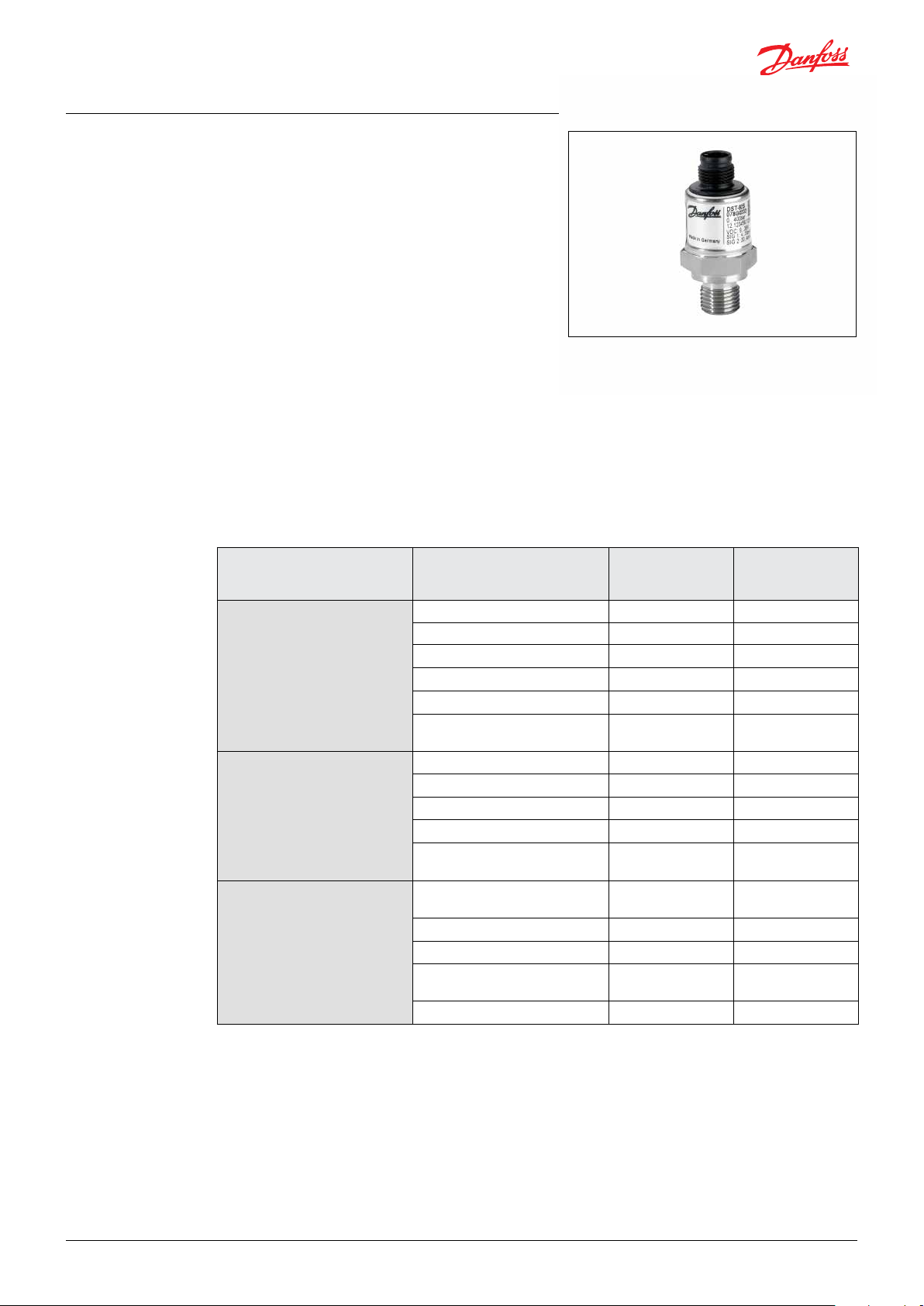
4. System information
The DST P92S is designed for the operation
in working machinery and further suitable
application areas and qualied especially for use
under harsh conditions.
The pressure transmitter is a passive intelligent
sensor. Its basically function is to convert the
physical quantity “pressure” to an electrical signal.
Available output types:
Curent variant:
Current output signal. This variant provides two
opposing current outputs 4 – 20 mA and
20 – 4 mA.
Ratiometric voltage variant:
Ratiometric voltage output signal. This variant
provides two opposing ratiometric voltage
outputs 10% * VCC – 90% * C and
90% * VCC – 10% ' VCC
4.1 Functional safety classication
The DST P92S has the following functional safety classication and parameters:
Standard Description Parameters of
current variant
Safety Integrity Level (SIL) 2
Architecture 1oo1 (single channel) 1oo1 (single channel)
IEC 61508/1/ (see “Reference” on
page 3)
EN ISO 13849-1 /2/ (see “Reference”
on page 3)
ISO 25119/EN 16590/5/(see
“Reference” on page 3)
Hardware Failure Tolerance (HFT) 0
Safety-related subsystem Type B
Safe Failure Fraction (SFF) 95.8% *
Average frequency of dangerous
failure per hour (PFH)
Performance Level (PL) d
Category (Cat.) 2
Avg. Diagnostic Coverage (DC
Common Cause Failures (CCF) 70 points
Mean Time To dangerous
Failure (MTTFD)
Agricultural Oerformance level
(AgPL)
Category (Cat)
Avg. Diagnostic Coverage (DC
Mean Time to Dangerous
Failure (MTTFdc)
Sofware Requirement Level (SRL)
6.1 x 10⁻⁹ 1/h
) 94.7% *
avg
981 years 2090 years
d d
2 2
)
94.7%* 91.0%*
avg
981 years 2090 years
Not relevant Not relevant
Parameters of the
ratiometric voltage
variant
2
0
Type B
93.1%*
4.9 x 10⁻⁹ 1/h
d
2
91.0%*
70 points
* with an external monitoring according to this safety guide
© Danfoss | DCS (im) | 2020.01
IC.PS.P21.2A.02 | 520B7782 | 13
Page 14

Safety guide | DST P92S Pressure transmitter
4.2 Technical data
Pressure
Parameter Min. Max.
Nominel pressure range 0 - 10 bar 0 - 1200 bar
Overload (depending on pressure range) 50 bar 2400 bar
Installation torque of the pressure connection
Current output
Parameter Min. Max.
Current within nominal pressure range 4 mA 20 mA
Current at o-state 0 mA 2 mA
Current accuracy output SIG1 (depending on ambient temperature)
Tolerance for plausibility check current output SIG1 +
output SIG2
Current load (depending on power supply) 0 Ω 1325 Ω
Electrical protection
15 Nm
1% FS
35 Nm
2.5 % FS
Depending
on application
2.5 % FS
and ECU
tolerance: e.g.
3%FS
Short circuit protected (signal
on GND/VCC)
NOTE
• The accuracy is only guaranteed under
reference conditions (T
medium
= T
ambient
).
• The maximum current load depends on the
power supply and is calculated by R
MAX
=
(+UB - 5.5 V) / 0.02 A.
Operating area for current outputs of the current variant
14 | © Danfoss | DCS (im) | 2020.01
IC.PS.P21.2A.02 | 520B7782
Page 15
Safety guide | DST P92S Pressure transmitter
Output of ratiometric voltage variant
Parameter of the ratiometric voltage outputs
Parameter Min. Max.
Relative voltage withnin nominal pressure range
Relative voltage at o-state
Accuracy of output SIG1 (depending on ambient temperature)
Accuracy plausibility check output SIG1 + output SIG2
(depending on ambient temperature
Load Resistance
Load current
Capacitive load
Electrical protection
WARNING
If the application operates at
maximum load limit, pressures above
100% FS can not be displayed!
10%* VCC
0 V
1% FS
2.5% FS
90%* VCC
5%* VCC
2.5% FS
Depending on
application and
ECU tolerance:
e.g. 3% FS
≥ 10 kΩ
-
-
Short circuit protected
(signal on GND/VCC)
-
1.3 mA
10 nF
Power supply
Parameter Min. Max.
9 V DC 32 V DC
Current variant: Voltage supply (power supply pin VCC)
Ratiometric voltage variant: Voltage supply (power supply pin VCC)
Supply lines inverse-polarity
protected
4.5 V DC 5.5 V DC
Supply lines inverse-polarity oritec
ted with current limit of up to 2 A
General accuracy
Parameter Min. Max.
Linearity, pressure hysteresis and repeatability - 0.5% FS
Long-run stability - 0.2% FS
Timing
Parameter Min. Max.
Startup - 40 ms
Response time - 2 ms
© Danfoss | DCS (im) | 2020.01
IC.PS.P21.2A.02 | 520B7782 | 15
Page 16

Safety guide | DST P92S Pressure transmitter
Mechanical data
Component Description
Housing Welded stainless steel
Degree of protection IP67, IP69K
Electrical connection M12
Pressure connection G¼, ¼ NPT, 7/16 - 20 UNF and 9/16 - 18 UNF
Installation torque Maximum 35 Nm
Material with medium contact EN/DIN 1.4548 / FK
Material housing EN/DIN 1.4301
Material diagphragm EN/DIN 1.4548
Material connector PBT-GF30
Dimensions (W x H x D) DST P92S G¼ with M12x1 PBT: 54 x 22 x 26 mm (wrenchsize 22)
Weight DST P92S with M12x1 PBT: ca. 50 g
Operating chassis temperature
Ratiometric voltage variant
Operating chassis temperature
Current variant
DT04
DST P92S G¼ with DT04x1 PBT: 65 x 22 x 26 mm (wrenchsize 22)
-40 °C – 85 °C
Electrical connection
4.3 Technical drawings
M1¼¼2x1 , 5-pole PBT DT04, 4-pole PBT
Ø21.3
Ø21.3
G¼ ¼ NPT 7/16-20 UNF 9/16-18 UNF
Pressure connection
16 | © Danfoss | DCS (im) | 2020.01
G¼
14 NPT
7/16-20 UNF
(SAE 4)
9/16-18 UNF
(SAE 8)
IC.PS.P21.2A.02 | 520B7782
Page 17

Safety guide | DST P92S Pressure transmitter
4.4 Pin conguration
M12x1 DT04
Pin 1: VCC Power supply
Pin 2: SIG2 Inverse pressure signal output
Pin 3: GND Common ground
Pin 4: SIG1 Pressure signal output
Pin 5: - Do not connect
4.5 Wiring diagram
4.6 Safety functions
Pin 1: VCC Power supply
Pin 2: GND Common ground
Pin 2: SIG2 Inverse pressure signal output
Pin 4: SIG1 Pressure signal output
© Danfoss | DCS (im) | 2020.01
The pressure transmitter DST P92S executes following safety function:
Safety function Safety integrity Error reaction DTI
safe conversion of the measured pressure into two
proportional redundant-opposing current signals
or ratiometric voltage signals
(0..100 %FS correspond to 4..20 mA or
0..100 %FS correspond to 10% * VCC .. 90% * VCC)
IEC 61508 / SIL-2
EN ISO 13849 / PLd
ISO 25119 / AgPld
“Fail safe” 80 ms
Safety relevance:
1. Accuracy of the sum of the single current
2. Maximum conversion delay
NOTE
The outputs of the DST P92S are not
safe by temselves but in combination
with a redundant signal processing.
IC.PS.P21.2A.02 | 520B7782 | 17
Page 18

Safety guide | DST P92S Pressure transmitter
4.7 Diagnosis
5. Safety requirements
The DST P92S uses several mechanisms to
detect faults in the electronic circuit. Those are
realized in a start-up and a cyclic diagnosis.
Cyclic Diagnosis
The cyclic diagnosis is made every 30-40ms and
includes:
• testing of the temperature sensor element
Start-Up Diagnosis
The start-up diagnosis is made once after
powering the DST P92S and includes internal
tests concerning e.g. the oscillator, the
watchdog or any memory. If the start-up
• testing of the pressure sensor concerning
drift, open circuit and short circuit
• testing of the sensor signal range
If the cyclic diagnosis detects a fault, the “Fail safe”
is entered as long as the fault is pending.
diagnosis detects a fault, the “Fail safe” is
entered. The DST P92S remains in the safe state.
The following diagram shows the pressure transmitter DST P92S is a typical application
Sensor_Y_DST P92S
NOTE
Information:
Safety requirements within this manual
are characterized by an identier like
SR_DST P92S_<index>. This can be
used to trace requirements that shall
be followed through the development
process of the application.
18 | © Danfoss | DCS (im) | 2020.01
IC.PS.P21.2A.02 | 520B7782
Page 19

Safety guide | DST P92S Pressure transmitter
5.1 Known issues
5.2 Instructions and constraints
NOTE
There are no known issues for the
DST P92S
Safety standards
REQUIREMENT
SR_DST P92S_001:
The current national and international
safety regulations, laws, and standards
for the whole safety lifecycle have to be
observed.
Qualication of sta
REQUIREMENT
SR_DST P92S_002:
The pressure transmitter DST P92S must
be installed and operated by trained,
qualied personnel only. The knowledge
and the technical implementation of
the safety information provided by
this manual are imperative for a safe
installation and operation.
Method statement
REQUIREMENT
SR_DST P92S_003:
Before setting the DST P92S into
operation for an application it is
necessary to read and follow the
instructions of this safety manual.
The limits of the technical data (see
“Technical Data” item 4.2) must be
complied within the application.
Proof test interval
REQUIREMENT
SR_DST P92S_004:
A proof test interval of the pressure
transmitter DST P92S must be initiated
and controlled every 7½ years.
As the DST P92S can not be recalibrated,
it has to be replaced, if the deviations
exceed the maximum tolerances.
Troubleshooting procedures
REQUIREMENT
SR_DST P92S_005:
A faulty transmitter must be replaced
immediately. There is no maintenance or
repair procedure provided for the
DST P92S
CE Conformity
REQUIREMENT
SR_DST P92S_014:
For CD conformity the following
restrictions have to be observed:
The length of the cables, which are
connected to pressure transmitter, must
not exceed 30 m.
© Danfoss | DCS (im) | 2020.01
5.3 Fail Safe
The state fail safe of the pressure transmitter
DST P92S
Type of DST P92S Signal State fail safe M12 DT04
Current variant
Ratiometric voltage
variant
The safe state is entered when the DST P92S
recognizes a fault condition.
Both outputs go into the safe state simultaneous.
Output SIG1 Iout < 2 mA Pin 4 Pin 4
Output SIG2 Iout < 2 mA Pin 2 Pin 3
Output SIG1 Uout < 5% * VCC Pin 4 Pin 4
Output SIG2 Uout < 5% * VCC Pin 2 Pin 3
NOTE
Specication:
The maximum time between a fault
occurrence and the safe state of the
DST P92S is 80 ms.
REQUIREMENT
SR_DST P92S_006:
The fault detection cycle of the
superordinate logic system must be long
enough to detect an error reliably.
IC.PS.P21.2A.02 | 520B7782 | 19
Page 20

Safety guide | DST P92S Pressure transmitter
Example:
The following time diagram shows the DST P92S
in a typical “sensor-logic-actuator” application
e.g. with and electronic control unit.
DST P92S Operation Interval
DST P92S Safe state
Reset condition
NOTE
Specication:
If a fault condition isn’t pending
continously, the DST P92S will leave the
safe state earliest after 60 ms.
REQUIREMENT
SR_DST P92S_007:
The diagnostic test interval of the
superordinate logic system must be short
enough to detect the safe state reliably.
5.4 System
System overview
Restrictions
WARNING
The safe state may not be entered during
an over- or under-voltage condition or
during startup. Possibly occurring spikes
on the outputs have to be ignored.
REQUIREMENT
SR_DST P92S_022:
The superordinate logic system has
to consider non-functional operating
modes, which do not lead to a safe state.
20 | © Danfoss | DCS (im) | 2020.01
REQUIREMENT
SR_DST P92S_008:
Exceeding the maximum supply voltage
of the DST P92S may cause an unsafe
operation. Therefore the superordinate
logic system has to monitor the sensor
power supply.
DST P92S
REQUIREMENT
SR_DST P92S_018:
Take measures to avoid an overvoltage
condition at the DST P92S.
IC.PS.P21.2A.02 | 520B7782
Page 21

Safety guide | DST P92S Pressure transmitter
REQUIREMENT
SR_DST P92S_009:
Running the DST P92S outside its
temperature limits may cause an unsafe
operation. Therefore the superordinate
logic system has to monitor the ambient
temperature.
REQUIREMENT
SR_DST P92S_019:
There have to be taken measures to
avoid an over- or under-temperature
condition at the DST P92S.
5.5 Pressure
The pressure is measured by a welded thin-lm
capsule, which converts the physical pressure
into an electrical signal by resistor full-bridge.
An additional temperature meander makes
itpossible to compensate the signal.
Functional diagram
REQUIREMENT
SR_DST P92S_021:
The chassis, in which the DST P92S is
mounted, has to be connected to the
power supply ground, to fulll the EMC
requirements.
© Danfoss | DCS (im) | 2020.01
REQUIREMENT
SR_DST 92S_010:
Because the radius of the pressure
channel of the DST P92S is very small,
measures must be taken for the pressure
system to prevent its clogging.
REQUIREMENT
SR_DST P92S_011:
Running the DST P92S outside its
temperature limits may cause an unsafe
operation. Therefore, the superordinate
logic system has to monitor the pressure
medium temperature.
REQUIREMENT
SR_DST 92S_024:
The thread shall be made of stainless
steel and shall be free of lubricant.
RECOMMENDATION
Avoid to exceed the specied pressure
ranges of the used DSR P92S. For a
smooth operation the pressure system
should be able to provide a stable nonuctuating pressure.
The accuracy of the pressure
measurement is only guaranteed under
reference conditions, that means if
the medium temperature and the
ambient temperature is nearly the same.
Therefore measures should be taken to
eect this.
IC.PS.P21.2A.02 | 520B7782 | 21
Page 22

Safety guide | DST P92S Pressure transmitter
WARNING
A drift of the measurement cell due to an
overpressure as well as an aging-related
drift can only be detected at the pressure
limits (0 %FS, 100 %FS) of the DST P92S.
5.6 Outputs
The outputs of the DST P92S are designed as
redundant inverted signals. The inverted signals
can be used to establish a redundant signal
processing for safety-related applications.
Signal diagram
Output signal Range of current variant Range of ratiometric voltage
variant
SIG1 4 – 20 mA 10% * VCC – 90% * VCC
SIG2 20 – 4 mA 90% * VCC – 10% * VCC
90% VCC /
20 mA
SIG2
10% VCC /
4 mA
REQUIREMENT
SR_DST P92S_012:
The superordinate logic system has to
provide safety-related input pairs, which
fulll the reservations of the
DST P92S outputs (see technical data
(see “Technical Data” item 4.2).
(Especially the requirements for the
minimum and maximum loading of the
current outputs have to be observed.)
REQUIREMENT
SR_DST P92S_020:
The superordinate logic system
has to process both output signals
simultaneously and to compare them in
a meaningful way.
SIG1
REQUIREMENT
SR_DST P92S_013:
The measured pressure is always
represented by output 1. Output 2 must
only be used for the safety function,
as it is not calibrated and temperature
compensated.
REQUIREMENT
SR_DST P92S_017
The superordinate logic system has to
check, if there is a short circuit between
the DST P92S outputs. Depending on the
applications, this must be done cyclically
or at start-up.
22 | © Danfoss | DCS (im) | 2020.01
RECOMMENDATION
For signal processing the two output
values should be accumulated by
the application and be compared to
predened limits (e.g. 24 mA ± 3 %FS).
IC.PS.P21.2A.02 | 520B7782
Page 23

Safety guide | DST P92S Pressure transmitter
Outputs of ratiometric voltage variant
With the ratiometric voltage variant the supply
and outout pins of the signal conditioning are
directly connected to the connector.
Output of current variant
With the current variant the signal conditioning
is supplied via a DC/DC converter and its outputs
are used to generate the current signals.
REQUIREMENT
SR_DST P92S_015:
A ratiometric voltage value of <7.5%*VCC
or >92.5%*VCC may be the result of
a damaged DST P92S. Therefore,, the
superordinate logic system must be able
to check the current range and react on
an invalid value.
REQUIREMENT
SR_DST P92S_025:
In case of an electronic ground loss
(GND), the two output signals have no
dened level. The superordinate logic
system must perform a plausibility check
of the two output signals (See SR_DST
P92S_020 and SR_DST_P92S_017).
© Danfoss | DCS (im) | 2020.01
REQUIREMENT
SR_DST P92S_016:
A current value < 3.5 mA or > 20.5 mA
may be the result of a damaged
DST P92S. Therefore the superordinate
logic system must be able to check the
current range and react on an invalid
value.
RECOMMENDATION
To check, if there is a short circuit
between the DST P92S current outputs,
one of them could be additional loaded,
e.g. with a programmable pull-down
resistor. The other one should not
change its value.
RECOMMENDATION
If the inputs of superordinate logic
system do not provide suitable load
resistors as required in the technical
data (see “Technical Data” item 4.2 ),
an additional series resistance can
be connected to the wiring. (See
“Examples”)
IC.PS.P21.2A.02 | 520B7782 | 23
Page 24

Safety guide | DST P92S Pressure transmitter
5.7 Decommissioning and disposal 5.8 Security
NOTE
For the DST P92S there has nothing to be
considered regarding decommissioning.
The disposal of the DST P92S has to be
done according to national laws.
6. Transport and storage
7. Maintenance There is no main tenance or repair procedure
8. Mounting
Transport
Check the pressure transmitter for possible
transport damage.
Do not use damaged deivces.
provided for the DST P92S (See “Instructions
and Constraints” item 5.2).
Preconditions
• Provide an ESD suitable environment
• Provide a dry and clean environment
• The thread and all sealing faces of the
pressure transmitter must be undamaged
and clean
• Apply the force to screw the pressure
sensor only through the spanner ats
provided for this purpose
• Select a cable diameter that matches the
cable connector of the mating plug
• Protect the cable end from humidity.
Otherwise humidity can intrude into the
instrument
See Mechanical Dimensions r needed space.
WARNING
Danger of serious injury and/or damage
to the equipment, when used beyond
the specied operative range.
Ensure to select the right type of
pressure transmitter according to:
• pressure range
• measurement range
• specic measurement conditions
NOTE
For the DST P92S there has nothing to be
considered regarding security.
Storage
Store the pressure transmitter in its original
packaging.
Remove the packaging only immediately before
mounting. The packaging provides protection
during storage and transport.
Required tools
Torque wrench: Width across ats 22
How to mount
WARNING
Danger of serious injury from sudden
escaping pressurized media.
Before opening any connections, make
sure to:
• Disconnect energy source
• Prevent reconnection
• Depressurize the system, including
pressure accumulators, lower upheld
load or provide compression-resistant
support for upheld load, remove
resifual energy
• Test the system for absence of
pressure
• Prevent danger due to adjacent
systems components
1. Screw the DST P92S into your system by
hand. Do not damage the thread, otherwise
a sealing connection cannot be established.
2. Tighten the DST P92S with the torque
wrench and a maxmimal screwing-torque of
35 Nm
3. Connect the connector with opposite plug:
Make sure the sealing of the connector is
present. Make sure to latch the connector
into the opposite plug.
4. Attach the used cables for DST P92S with
a cable relief. No force must act on the
connector and cables. Do not bend the cable
with a radius smaller than 18 mm.
24 | © Danfoss | DCS (im) | 2020.01
IC.PS.P21.2A.02 | 520B7782
Page 25

Safety guide | DST P92S Pressure transmitter
9. Dismounting Preconditions
• Provide an ESD suitable environment
• The connected pressure transmitter must
be cleaned
• Apply the force to screw o the pressure
transmitter only through the spanner ats
provided for this purpose
Required tools
Wrench: Width across ats 22
How to dismount
WARNING
Danger of serious injury from sudden
escaping pressurized media.
Before opening any connections, make
sure to:
• Disconnect energy source
• Prevent reconnection
• Depressurize the system,
including pressure accumulators,
lower upheld load or provide
compression-resistant support for
upheld load, remove resifual energy
• Test the system for absence of
pressure
• Prevent danger due to adjacent
systems components
1. Make sure the system is depressurized.
2. Remove cable relief from the cables. Do not
damage the cables.
3. Disconnect the connetor from mating plug.
4. Screw of DST P92S from your system with
the wrench. Do not damage the threads.
© Danfoss | DCS (im) | 2020.01
IC.PS.P21.2A.02 | 520B7782 | 25
Page 26
Danfoss A/S
Industrial Automation
Nordborgvej 81
DK-6430 Nordborg
Denmark
www.ia.danfoss.com
© Danfoss | DCS (im) | 2020.01
IC.PS.P21.2A.02 | 520B7782 | 26
 Loading...