

Data sheet
Pressure transmitter SIL-2
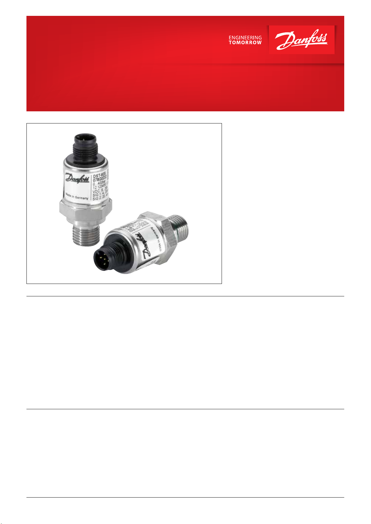
DST P92S
The DST P92S OEM pressure transmitter is
designed for use in Mobile and Industrial
hydraulic applications.
The transmitter is suitable for use in a functional
safety environment with a requirement of PLd,
EN ISO 13849-1: 2015 or AgPLd EN ISO 25119:
2010 or SIL2, IEC 61508:2010, respectively.
Further Danfoss holds a third party approval from
TÜV to ensure easy implementation into any
safety system.
Features
Conformity
• Designed for use in severe hydraulic
applications
• For operating temperature up to 85 °C
• Pressure range 0-10 bar to 0-1200 bar
• Dual output signal: 4-20 / 20 -4 mA or
ratiometric 10-90 / 90-10%
• PLd EN ISO 13849-1: 2015
• AgPLd EN ISO 25119 :2010
• SIL2 IEC 61508: 2010
• CE marked
• ECE type approval
Note: In respect to Customer Change Notification, only changes in relation to Form Fit and
Function can be informed upon!
• Cyclic diagnostic
• Start up diagnostic
• Wetted parts made of stainless steel
• Designed towards OEM requirements
© Danfoss | DCS (im) | 2020.05 AI270826119130en-000401 | 520B8334 | 1
Data sheet | Pressure transmitter SIL2, DST P92S
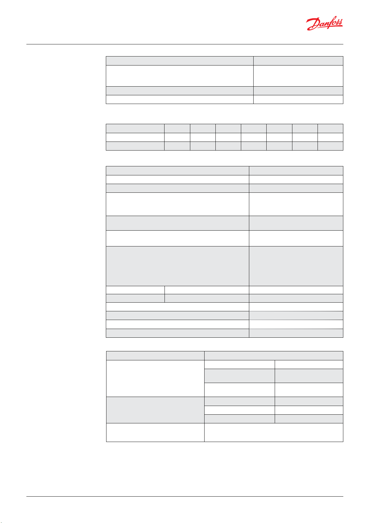
Technical data
Accuracy (incl. non linearity, hysteresis and repeatability) < 0.5% FS 1
+/- 1% FS [0 – 85 °c]
Overall accuracy under reference conditions
+/- 1,5% FS [-25 – 0 °c]
+/- 2,5% FS [-40 – -25 °c]
Long-run stability <0,2% FS p.a.
Response time liquids (10 – 90%) 2 ms
1
1, Load 100 Ω, temperature in steady state, accuracy valid for output 1 for 4 – 20 mA
Overload and burst pressure
Standard pressure [bar] 40 60 100 160 250 400 600
Overload pressure [bar] 80 120 200 320 500 800 1200
Burst pressure [bar] 400 600 1000 1600 2500 4000 >4000
Environmental conditions
Media temperature range - 40 – 125 °C
Operating temperature range -40 – 85 °C
Storage temperature range -40 – 100 °C
Voltage supply
Electrical Protection
Electric Magnetic Compatibility Directive [EMC] 2014/30/EU
9 – 32 V DC, alloable ripple @50Hz: 10% (for
current output)
5V ±10% (for ratiometric voltage output)
Short circuit protected, signal on GND/VCC
and reverse polarity protection
DIN EN 61326-1
DIN EN 61326-2-3
EMC
DIN EN 61326-3-1
E1 type approval: All vehicle types with a 12 V
or 24 V - electrical wiring and battery (-) at
the body
Vibration stability 20 g EN60068-2-6
Shock mechanical 500 g EN60068-2-27
Enclosure 1.4301/ PBT-GF30
Material with medium contact 1.4548/Viton
Weight 50 g
Enclosure IP67
Functional safety
Machinery Directive [MD] 2006/42/EC
SIL 2 Safety related subsystem, type B
IEC 61508:2010
EN ISO 13849-1:2015
Safety function
1oo1 architecture
HFT 0
PL d CCF 70 points
Category 2 MTTF
DC medium (incl. control unit)
Safety conversion of the measured pressure into two proportional
opposing current signals. Refer also to the Safety guide.
SFF 95.8% 4-20mA / 93,1%
ratiometric (incl. control unit)
PFH 6.1*10
(ratiometric)
-9
(4-20 mA) / 4.9*10
high >100 years
d
-9
2 | 520B8334 | AI270826119130en-000401
© Danfoss | DCS (im) | 2020.05

Data sheet | Pressure transmitter SIL2, DST P92S
Danfoss
Ordering Available code numbers
Type Measuring range Pressure connection Electrical connection Electrical output Code no
DST P92S 0 – 40 bar G1/4 DIN 3852-E M12 4-20mA / 20-4mA 078G1000
DST P92S 0 – 60 bar G1/4 DIN 3852-E M12 4-20mA / 20-4mA 078G1001
DST P92S 0 – 100 bar G1/4 DIN 3852-E M12 4-20mA / 20-4mA 078G1002
DST P92S 0 – 160 bar G1/4 DIN 3852-E M12 4-20mA / 20-4mA 078G1003
DST P92S 0 – 250 bar G1/4 DIN 3852-E M12 4-20mA / 20-4mA 078G1004
DST P92S 0 – 400 bar G1/4 DIN 3852-E M12 4-20mA / 20-4mA 078G1005
DST P92S 0 – 600 bar G1/4 DIN 3852-E M12 4-20mA / 20-4mA 078G1006
For other requests please see below and/or contact Danfoss.
Dimensions
M12x1, 5-pole PBT DT04-4p, 4-pole PBT
Ø21.3
Electrical connection
Pressure connection G¼ DIN3852-E Viton gasket 7/16 - 20 UNF 9/16 - 18 UNF
A78G07
Gasket
22.5
G1/4
DIN 3869
7/16-20 UNF
(SAE 4)
9/16-18 UNF
(SAE 8)
Recommended torque Max. 35 Nm
© Danfoss | DCS (im) | 2020.05
AI270826119130en-000401 | 520B8334 | 3

Electrical connections
GND
Danfoss
5
3
2
Danfoss
M12x1, 5-pole PBT DT04-4p, 4-pole PBT
4
Pin Configurations
A78G09
1
Enclosure
(IP protection fulfilled together with mating
connector)
Material
Pin 1: VCC
Electrical connections
4 - 20 mA/20 - 4 mA (3 wire)
Pin 2: Output 2 [20 – 4 mA]
Pin 3: GND
Pin 4: Output 1 [4 – 20 mA]
Pin 5: Do not connect
Pin 1: VCC
Electrical connections
10-90 / 90-10% ratiometric
Pin 2: Output 2 [90 – 10%]
Pin 3: GND
Pin 4: Output 1 [10 – 90%]
Pin 5: Do not connect
–
IP67 IP67
PBT PBT
Pin 1: VCC
Pin 2: GND
Pin 3: Output 2 [20 – 4 mA]
Pin 4: Output 1 [4 – 20 mA]
Pin 1: VCC
Pin 2: GND
Pin 3: Output 2 [90 –10% VCC]
Pin 4: Output 1 [10 – 90% VCC]
Recommended terminal layout
A78G08
For detailed load reference please refer to the Safety guide.
RLR
VCC
OUT 1
OUT 2
L
© Danfoss | DCS (im) | 2020.05
AI270826119130en-000401 | 520B8334 | 4
 Loading...