

Page 1
Operation guide
Pressure transmitter
CAN SAE J1939
DST P92C
ia.danfoss.com
Page 2

Operation guide | DST P92C Pressure transmitter CAN SAE J1939
Table of contents
1. General Information
Contents
1. General information................................................................................................................................... 2
1.1 Contact........................................................................................................................................................... 2
1.2 General............................................................................................................................................................ 2
1.3 CAN Interface................................................................................................................................................ 3
2. Specifications............................................................................................................................................... 3
3. J1939 communication.............................................................................................................................. 3
3.1 Introduction................................................................................................................................................. 3
3.2 Supported PGN’s and SPN’s.................................................................................................................... 4
3.3 PGN of Danfoss........................................................................................................................................... 10
3.4 Definitions..................................................................................................................................................... 11
3.4.1 PGN.................................................................................................................................................................. 11
3.4.2 SPN.................................................................................................................................................................. 11
3.5 Overview of the slot for pressure sensors......................................................................................... 11
3.6 Additionally, Danfoss specific ............................................................................................................... 12
3.7 References.................................................................................................................................................... 12
1.1 Contact
Danfoss A/S
Industrial Automation
DK-6430 Nordborg
Denmark
www.ia.danfoss.com
E-mail: technical support_IA@danfoss.com
1.2 General
The pressure transmitter DST P92C measures the
physical quantity pressure. The range depends on
the sensor which is used in the transmitter and
is 25–800 bar. The measured value is transmitted
on the CAN-Bus with the J1939 protocol. The
transmitter takes 1000 samples per second, does
filtering and converts the raw value into the
output format.
The CAN 2.0B interface is able to run up to
a speed of 1 Mbit/sec with 11-bit and 29-bit
identifiers.
1.3 CAN Interface
The device includes a Full CAN controller
specified to CAN 2.0B. The physical layer of the
2-wire interface is specified according to ISO
11898. The wires are protected against shortcircuit. By adjusting the rise and fall times of the
CAN signals, the noise emission is minimized.
The bus termination resistor is not included in
the device.
2 | © Danfoss | DCS (im) | 2018.01
IC.PS.P21.2C.02 | 520B7799
Page 3
Operation guide | DST P92C Pressure transmitter CAN SAE J1939
5
3
2
Danfoss
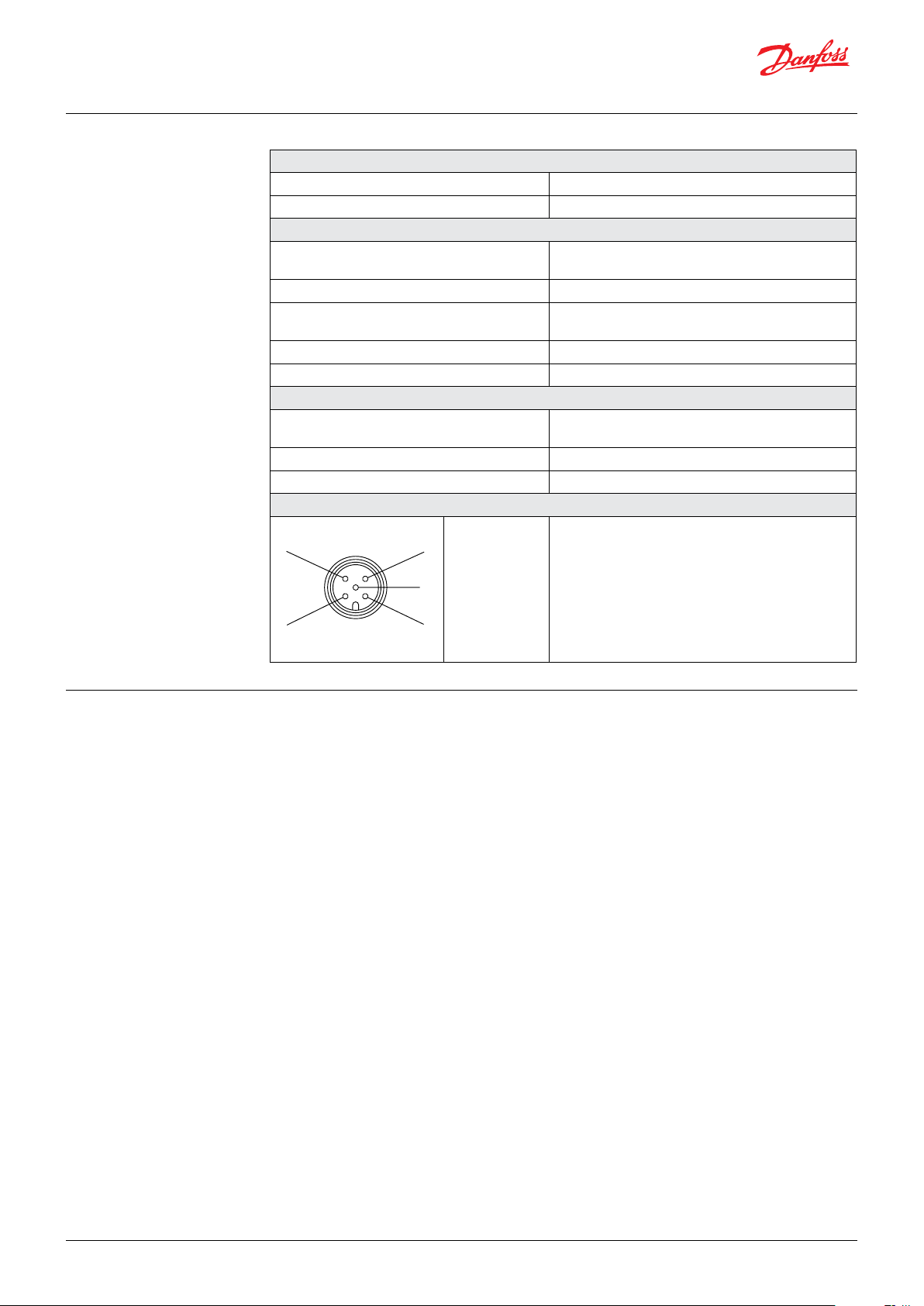
2. Specifications
Electrical specifications
Supply voltage 9 – 36 V DC protected against reverse polarity
Current consumption at U
= 24 V DC I < 50 mA typical, IMAX < 100 mA
S
CAN Interface
Physical layer
2-wire interface, 5 V level according to ISO 11898
Protected against short-circuit
Bit rate 250 kBit/s
Signal rise time
Bit rate < 125 kbit/s 12 V/µs (without bus)
Bit rate ≥ 125 kbit/s > 24 V/µs (without bus)
Bus termination External
Protokoll SAE J1939
Environment
EMC
EN 61000-6-2
EN 61000-6-4
Operating temperature -40 – 125 °C
Media temperature -40 – 150 °C
M12 connector Pin Assignment (CiA DR303-1)
4
A78G09
1
Pin 1
Pin 2
Pin 3
Pin 4
Pin 5
CAN shield, PE
+U
, +24 V DC
B
GND, 0 V
CAN_H, CAN+
CAN_L, CAN-
3. J1939 Communication
3.1 Introduction
The Society of Automotive Engineers (SAE)
developed the 1939 standard to be the
preferred CAN for equipment used in industries
ranging from agriculture, construction, and fire/
rescue to forestry, materials handling as well as
on and off-highway vehicles. It is a high-level
protocol that defines how communication
between nodes (modules) occurs on the bus.
The 1939 network is a specific communication
system, supporting specific sets of applications
and a specific industry, rather than being
generalized.
Any electronic control unit (ECU) using J1939
is permitted to transmit a message on the
network when the bus is idle. Every message
includes a 29-bit identifier, which defines the
message priority, what data is contained within
the 8-byte data array that follows the identifier,
and which ECU sent the message.
© Danfoss | DCS (im) | 2018.01
IC.PS.P21.2C.02 | 520B7799 | 3
Page 4
Operation guide | DST P92C Pressure transmitter CAN SAE J1939
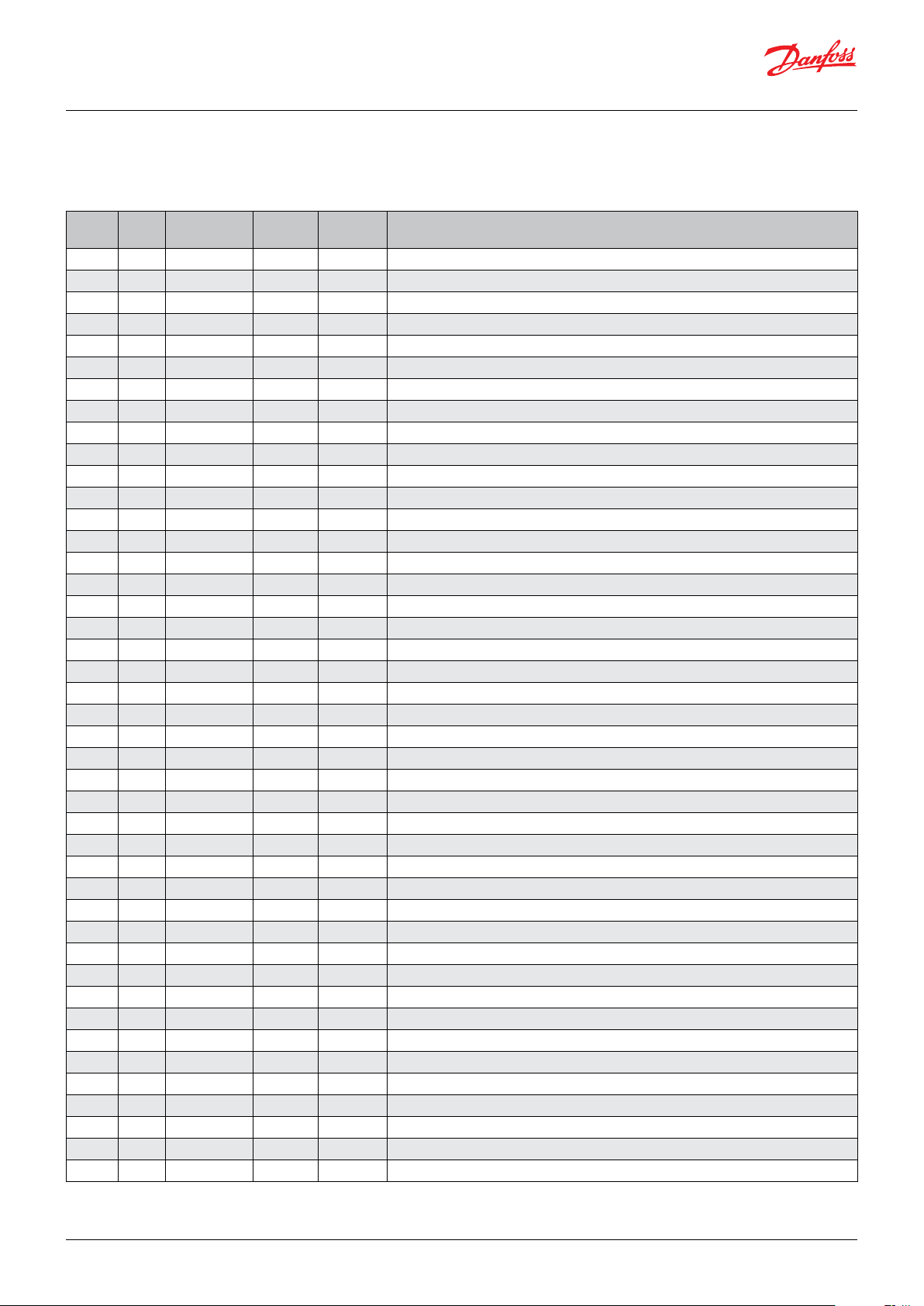
3.2 Supported PGN’s and SPN’s
PGN’s of SAE J1939
PGN SPN TTR [ms]
61448 1762 50 1-2 SAEpr08 Hydraulic Pressure
61448 6707 50 4-5 SAEpr20 Hydraulik Intake Pressure
61448 6708 50 6-7 SAEpr08 Hydraulic Discharge Pressure Set Point
61475 4334 50 6 SAEpr13 Aftertreatment 1 Diesel Exhaust Fluid Doser 1 Absolute Pressure
61478 4387 50 6 SAEpr13 Aftertreatment 2 Diesel Exhaust Fluid Doser 1 Absolute Pressure
61538 6583 10 1-2 SAEpr22 Tranmission Hydrostatic Loop 1 Pressure
61538 6584 10 3-4 SAEpr22 Tranmission Hydrostatic Loop 2 Pressure
64557 6787 500 1-2 SAEpr03 LNG Tank 1 Vapor Pressure
64557 6788 500 3-4 SAEpr03 LNG Tank 2 Vapor Pressure
64559 7350 1000 4 SAEpr13 Fire Suppression Compressed Air Foam System Air Pressure
64563 7100 500 1-2 SAEpr12 Engine Injector Metering Rail 1 Desired Pressure
64563 7101 500 3-4 SAEpr12 Engine Injector Metering Rail 2 Desired Pressure
64564 7096 500 1-2 SAEpr12 Engine Injector Metering Rail 1 Pressure 1 (Extended Range)
64564 7097 500 3-4 SAEpr12 Engine Injector Metering Rail 1 Pressure 2 (Extended Range)
64564 7098 500 5-6 SAEpr12 Engine Injector Metering Rail 2 Pressure 1 (Extended Range)
64564 7099 500 7-8 SAEpr12 Engine Injector Metering Rail 2 Pressure 2 (Extended Range)
64569 7067 500 1-2 SAEpr06 Plant Gaseous Fuel Supply Outlet Pressure
64569 7068 500 3-4 SAEpr06 Plant Inert Gas Supply Outlet Pressure
64570 7063 500 1-2 SAEpr06 Engine Gaseous Fuel Supply Pressure 2
64570 7064 500 3-4 SAEpr06 Gaseous Fuel Supply Unit Intake Pressure
64570 7065 500 5-6 SAEpr06 Gaseous Fuel Supply Shutoff Valve 1 Intake Pressure
64570 7066 500 7-8 SAEpr06 Gaseous Fuel Supply Shutoff Valve 2 Intake Pressure
64576 7019 500 4-5 SAEpr08 Engine Fuel 2 Pump Hydraulic Pressure
64577 7021 500 1-2 SAEpr08 Engine Fuel 2 Injector Metering Rail 1 Pressure
64577 7022 500 3-4 SAEpr08 Engine Fuel 2 Injector Metering Rail 2 Pressure
64577 7513 500 7-8 SAEpr08 Engine Fuel 2 Injector Metering Rail 1 Pressure 2
64578 6988 10000 2-3 SAEpr22 Time Pressure (Extended Range)
64578 6989 10000 4-5 SAEpr22 Required Tire Pressure
64579 6980 on request 2-3 SAEpr22 Cold Inflation Pressure
64589 6876 500 1 SAEpr10 Aftertreatment 2 Diesel Exhaust Fluid Dosing Pressure
64590 6875 500 1 SAEpr10 Aftertreatment 1 Diesel Exhaust Fluid Dosing Pressure
64590 7459 500 2 SAEpr13 Aftertreatment 1 Diesel Exhaust Fluid Doser 2 Absolute Pressure
64595 6837 500 4 SAEpr10 Gas Leakage Detection 1 Pressure
64595 6838 500 5 SAEpr10 Gas Leakage Detection 2 Pressure
64595 6839 500 6 SAEpr10 Gas Leakage Detection 3 Pressure
64600 6811 1000 1 SAEpr10 Engine Turbocharger 2 Lube Oil Pressure
64600 6812 1000 2 SAEpr10 Engine Turbocharger 3 Lube Oil Pressure
64600 6813 1000 3 SAEpr10 Engine Turbocharger 4 Lube Oil Pressure
64655 6646 100 1 SAEpr09 Engine Gaseous Fuel Supply Pressure (Extended Range)
64656 6589 500 1-2 SAEpr09 Engine Injector Metering Rail 1 Pressure 1
64656 6590 500 3-4 SAEpr09 Engine Injector Metering Rail 1 Pressure 2
64656 6591 500 5-6 SAEpr09 Engine Injector Metering Rail 2 Pressure 1
64656 6592 500 7-8 SAEpr09 Engine Injector Metering Rail 2 Pressure 2
Data
Position
Slot SPN Name
4 | © Danfoss | DCS (im) | 2018.01
IC.PS.P21.2C.02 | 520B7799
Page 5

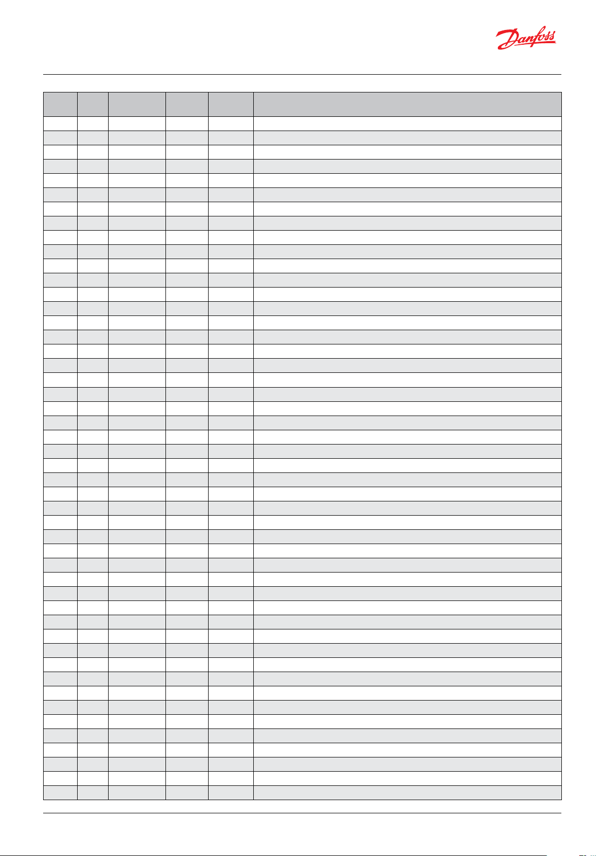
Operation guide | DST P92C Pressure transmitter CAN SAE J1939
PGN SPN TTR [ms]
64659 6571 on request 1-2 SAEpr03 Engine Main Chamber Fuel Absolute Pressure
64659 6572 on request 3-4 SAEpr03 Engine Main Chamber Fuel Desired Absolute Pressure
64659 6573 on request 5-6 SAEpr03 Engine Prechamber Fuel Absolute Pressure
64659 6574 on request 7-8 SAEpr03 Engine Prechamber Fuel Desired Absolute Pressure
64662 6384 100 1-2 SAEpr04 Engine Exhaust Pressure 1 (Extended Range)
64662 7470 100 3-4 SAEpr03 Engine Pre-Filter Oil Pressure (High Resolution/Extended Range)
64671 6321 1000 1-2 SAEpr01 Engine Oil Filter Differential Pressure (Extended Range)
64705 5927 1000 1 SAEpr14 Transmission Clutch 2 Pressure
64733 5590 500 1-2 SAEpr03 Aftertreatment 2 Secondary Air Absolute Pressure
64734 5589 500 1-2 SAEpr03 Aftertreatment 1 Secondary Air Absolute Pressure
64735 5578 500 1 SAEpr10 Engine Fuel Delivery Absolute Pressure
64735 5579 500 2 SAEpr10 Engine Filtered Fuel Delivery Pressure
64735 5580 500 3 SAEpr10 Engine Filtered Fuel Delivery Absolute Pressure
64735 6816 500 5 SAEpr17 Engine Fuel Return Pressure
64735 7472 500 8 SAEpr11 Engine Fuel Supply Pump Intake Absolute Pressure (Extended Range)
64739 5541 100 1 SAEpr07 Engine Turbocharger 1 Turbine Outlet Pressure
64739 5542 100 2 SAEpr07 Engine Turbocharger 1 Turbine Desired Outlet Pressure
64739 5544 100 4 SAEpr07 Engine Turbocharger 2 Turbine Outlet Pressure
64739 5545 100 5 SAEpr07 Engine Turbocharger 2 Turbine Desired Outlet Pressure
64751 5430 500 1-2 SAEpr03 Engine Exhaust Gas Recirculation 1 Intake Absolute Pressure
64751 5431 500 3-4 SAEpr03 Engine Exhaust Gas Recirculation 1 Outlet Absolute Pressure (High Resolution)
64751 7468 500 5-6 SAEpr03 Engine Oil Pressure (High Resolution/Extended Range)
64751 7469 500 7-8 SAEpr03 Engine Fuel Delivery Pressure (High Resolution/Extended Range)
64752 5417 500 1 SAEpr07 Engine Fuel Filter (Suction Side) Intake Absolute Pressure
64752 7395 500 4-5 SAEpr03 Fuel Tank Transfer Pump Pressure
64765 5313 100 5-6 SAEpr09 Commanded Engine Fuel Rail Pressure
64765 5314 100 7-8 SAEpr09 Commanded Engine Fuel Injection Control Pressure
64766 5259 on request 3-4 SAEpr06 Engine Exhaust Gas Recirculation 2 Cooler Intake Gas Absolute Pressure
64768 5252 500 1-2 SAEpr01 Engine Exhaust Gas Recirculation 2 Differential Pressure
64768 5253 500 3 SAEpr07 Engine Exhaust Gas Recirculation 2 Intake Pressure
64768 5254 500 4-5 SAEpr03 Engine Exhaust Gas Recirculation 2 Outlet Absolute Pressure
64768 5429 500 6-7 SAEpr03 Engine Exhaust Gas Recirculation 2 Intake Absolute Pressure
64768 5708 500 8 SAEpr07 Engine Coolant Pressure 2
64799 4773 500 5-6 SAEpr06 Aftertreatment 2 Diesel Oxidation Catalyst Differential Pressure
64800 4767 500 5-6 SAEpr03 Aftertreatment 1 Diesel Oxidation Catalyst Differential Pressure
64801 4761 500 SAEpr03 Aftertreatment 2 Gas Oxidation Catalyst Differential Pressure
64802 4755 500 5-6 SAEpr03 Aftertreatment 1 Gas Oxidation Catalyst Differential Pressure
64817 1707 1000 5-6 SAEpr06 Hydraulic Fan 2 Motor Pressure
64825 4411 500 1-2 SAEpr03 Aftertreatment 2 SCR Differential Pressure
64825 6587 500 4-5 SAEpr18 Aftertreatment 2 SCR Intake Pressure
64825 6798 500 6-7 SAEpr03 Aftertreatment 2 SCR Intake Absolute Pressure
64827 4388 500 1 SAEpr13 Aftertreatment 2 SCR Dosing Air Assist Absolute Pressure
64831 4358 500 1-2 SAEpr03 Aftertreatment 1 SCR Differential Pressure
64831 6586 500 4-5 SAEpr18 Aftertreatment 1 SCR Intake Pressure
64831 6797 500 6-7 SAEpr03 Aftertreatment 1 SCR Intake Absolute Pressure
64833 4335 500 1 SAEpr13 Aftertreatment 1 SCR Dosing Air Assist Absolute Pressure
64836 4303 500 1-2 SAEpr03 Aftertreatment 2 Fuel Pressure 2
64837 4297 500 5-6 SAEpr03 Aftertreatment 2 Three Way Catalyst Differential Pressure
Data
Position
Slot SPN Name
© Danfoss | DCS (im) | 2018.01
IC.PS.P21.2C.02 | 520B7799 | 5
Page 6

Operation guide | DST P92C Pressure transmitter CAN SAE J1939
PGN SPN TTR [ms]
64838 4291 500 5-6 SAEpr03 Aftertreatment 1 Three Way Catalyst Differential Pressure
64869 4077 500 1-2 SAEpr03 Aftertreatment 1 Fuel Pressure 2
64876 3833 500 1-2 SAEpr01 Aftertreatment 2 Secondary Air Differential Pressure
64876 3838 500 7-8 SAEpr03 Aftertreatment 2 Secondary Air Pressure
64877 3830 500 1-2 SAEpr01 Aftertreatment 1 Secondary Air Differential Pressure
64877 3837 500 7-8 SAEpr03 Aftertreatment 1 Secondary Air Pressure
64879 4751 on request 5-6 SAEpr06 Engine Exhaust Gas Recirculation 1 Cooler Intake Absolute Pressure
64900 3640 500 1-2 SAEpr03 Engine Intake Valve Actuation Oil Pressure for Cylinder #17
64900 3641 500 3-4 SAEpr03 Engine Intake Valve Actuation Oil Pressure for Cylinder #18
64900 3642 500 5-6 SAEpr03 Engine Intake Valve Actuation Oil Pressure for Cylinder #19
64900 3643 500 7-8 SAEpr03 Engine Intake Valve Actuation Oil Pressure for Cylinder #20
64901 3636 500 1-2 SAEpr03 Engine Intake Valve Actuation Oil Pressure for Cylinder #13
64901 3637 500 3-4 SAEpr03 Engine Intake Valve Actuation Oil Pressure for Cylinder #14
64901 3638 500 5-6 SAEpr03 Engine Intake Valve Actuation Oil Pressure for Cylinder #15
64901 3639 500 7-8 SAEpr03 Engine Intake Valve Actuation Oil Pressure for Cylinder #16
64902 3632 500 1-2 SAEpr03 Engine Intake Valve Actuation Oil Pressure for Cylinder #9
64902 3633 500 3-4 SAEpr03 Engine Intake Valve Actuation Oil Pressure for Cylinder #10
64902 3634 500 5-6 SAEpr03 Engine Intake Valve Actuation Oil Pressure for Cylinder #11
64902 3635 500 7-8 SAEpr03 Engine Intake Valve Actuation Oil Pressure for Cylinder #12
64903 3628 500 1-2 SAEpr03 Engine Intake Valve Actuation Oil Pressure for Cylinder #5
64903 3629 500 3-4 SAEpr03 Engine Intake Valve Actuation Oil Pressure for Cylinder #6
64903 3630 500 5-6 SAEpr03 Engine Intake Valve Actuation Oil Pressure for Cylinder #7
64903 3631 500 7-8 SAEpr03 Engine Intake Valve Actuation Oil Pressure for Cylinder #8
64904 3624 500 1-2 SAEpr03 Engine Intake Valve Actuation Oil Pressure for Cylinder #1
64904 3625 500 3-4 SAEpr03 Engine Intake Valve Actuation Oil Pressure for Cylinder #2
64904 3626 500 5-6 SAEpr03 Engine Intake Valve Actuation Oil Pressure for Cylinder #3
64904 3627 500 7-8 SAEpr03 Engine Intake Valve Actuation Oil Pressure for Cylinder #4
64907 3611 500 1-2 SAEpr03 Aftertreatment 2 Diesel Particulate Filter Intake Pressure
64907 3612 500 3-4 SAEpr03 Aftertreatment 2 Diesel Particulate Filter Outlet Pressure
64908 3609 500 1-2 SAEpr03 Aftertreatment 1 Diesel Particulate Filter Intake Pressure
64908 3610 500 3-4 SAEpr03 Aftertreatment 1 Diesel Particulate Filter Outlet Pressure
64916 5312 100 7-8 SAEpr04 Engine Intake Manifold Commanded Pressure
64926 3499 500 1-2 SAEpr03 Aftertreatment 2 Supply Air Pressure
64926 3500 500 3-4 SAEpr03 Aftertreatment 2 Purge Air Pressure
64927 3485 500 1-2 SAEpr03 Aftertreatment 1 Aupply Air Pressure
64927 3486 500 3-4 SAEpr03 Aftertreatment 1 Purge Air Pressure
64928 3494 500 1-2 SAEpr03 Aftertreatment 2 Fuel Pressure 1
64929 3480 500 1-2 SAEpr03 Aftertreatment 1 Fuel Pressure 1
64930 3466 500 1-2 SAEpr03 Engine Fuel Valve 2 Intake Absolute Pressure
64930 3469 500 7-8 SAEpr03 Engine Fuel Valve 2 Outlet Absolute Pressure
64938 3340 500 1 SAEpr07 Engine Charge Air Cooler 1 Intake Pressure
64938 3341 500 2 SAEpr07 Engine Charge Air Cooler 2 Intake Pressure
64938 3342 500 3 SAEpr17 Engine Coolant Pump Differentieal Pressure
64938 2631 500 8 SAEpr07 Engine Charge Air Cooler Outlet Pressure
64943 3285 500 5-6 SAEpr03 Aftertreatment 2 Diesel Particulate Filter Differential Pressure
64946 3251 500 5-6 SAEpr03 Aftertreatment 1 Diesel Particulate Filter Differential Pressure
64953 3191 on request 2 SAEpr13 Reference Tire Pressure
64961 2948 500 1-2 SAEpr09 Engine Intake Valve Actuation System Oil Pressure
Data
Position
Slot SPN Name
6 | © Danfoss | DCS (im) | 2018.01
IC.PS.P21.2C.02 | 520B7799
Page 7
Operation guide | DST P92C Pressure transmitter CAN SAE J1939
PGN SPN TTR [ms]
64961 3358 500 3 SAEpr07 Engine Exhaust Gas Recirculation 1 Intake Pressure
64961 4287 500 4-5 SAEpr09 Engine Exhaust Valve Actuation System Oil Pressure
64961 5019 500 6 SAEpr07 Engine Exhaust Gas Recirculation 1 Outlet Pressure
64961 5631 500 7-8 SAEpr03 Engine Throttle Valve 1 Differential Pressure
64976 2809 500 1 SAEpr02 Engine Air Filter 2 Differential Prssure
64976 2810 500 2 SAEpr02 Engine Air Filter 3 Differential Prssure
64976 2811 500 3 SAEpr02 Engine Air Filter 4 Differential Prssure
64976 3562 500 4 SAEpr07 Engine Intake Manifold #2 Pressure
64976 3563 500 5 SAEpr07 Engine Intake Manifols #1 Absolute Pressure
64976 4817 500 6-7 SAEpr03 Engine Intake Manifold 1 Absolute Pressure (High Resolution)
64976 5422 500 8 SAEpr07 Engine Intake Manifold 2 Absolute Pressure
64992 5685 1000 7-8 SAEpr03 Barometric Absolute Pressure (High Resolution)
64993 2609 1000 1 SAEpr14 Cab A/C Refrigerant Compressor Outlet Pressure
64994 2603 1000 1 SAEpr13 Pneumatic Supply Pressure Request
64994 2604 1000 2 SAEpr13 Parking and/or Trailer Air Pressure Request
64994 2605 1000 3 SAEpr13 Service Brake Air Pressure Request, Circuit #1
64994 2606 1000 4 SAEpr13 Service Brake Air Pressure Request, Circuit #2
64994 2607 1000 5 SAEpr13 Auxiliary Equipment Supply Pressure Request
64994 2608 1000 6 SAEpr13 Air Suspension Supply Pressure Request
64994 6306 1000 7 SAEpr13 Powertrain Circuit Air Supply Pressure Request
64998 2580 100 1 SAEpr15 Hydraulic Brake Pressure Circuit 1
64998 2581 100 2 SAEpr15 Hydraulic Brake Pressure Circuit 2
65112 1725 100 1-2 SAEpr03 Bellow Pressure Front Axle Left
65112 1726 100 3-4 SAEpr03 Bellow Pressure Front Axle Right
65112 1727 100 5-6 SAEpr03 Bellow Pressure Rear Axle Left
65112 1728 100 7-8 SAEpr03 Bellow Pressure Rear Axle Right
65130 1381 500 2 SAEpr07 Engine Fuel Supply Pump Intake Absolute Pressure
65130 1382 500 3 SAEpr07 Engine Fuel Filter (suction side) Differential Pressure
65130 3549 500 5 SAEpr10 Engine Oil-Filter Outlet Pressure
65130 7104 500 8 SAEpr07 Engine Fuel Supply Pump Intake Pressure
65143 136 on request 1-2 SAEpr06 Auxiliary Vacuum Pressure Reading
65143 137 on request 3-4 SAEpr06 Auxiliary Gage Pressure Reading 1
65143 138 on request 5-6 SAEpr06 Auxiliary Absolute Pressure Reading
65145 141 on request 1-2 SAEpr06 Trailer, Tag or Push Channel Tire Pressure Target
65145 142 on request 3-4 SAEpr06 Drive Channel Tire Pressure Target
65145 143 on request 5-6 SAEpr06 Steer Channel Tire Pressure Target
65146 144 on request 1-2 SAEpr06 Trailer, Tag or Push Channel Tire Pressure
65146 145 on request 3-4 SAEpr06 Drive Channel Tire Pressure
65146 146 on request 5-6 SAEpr06 Steer Channel Tire Pressure
65163 1390 on request 1-2 SAEpr03 Engine Fuel Valve 1 Intake Absolute Pressure
65163 1391 on request 3-4 SAEpr03 Engine Fuel Valve 1 Differential Pressure
65163 1392 on request 5-6 SAEpr03 Engine Air to Fuel Differential Pressure
65163 2980 on request 7-8 SAEpr03 Engine Fuel Valve 1 Outlet Absolute Pressure
65164 1387 on request 3 SAEpr14 Auxiliary Pressure #1
65163 1388 on request 4 SAEpr14 Auxiliary Pressure #2
65167 1320 1000 1-2 SAEpr06 Engine External Shutdown Air Supply Pressure
65170 1208 100 1 SAEpr10 Engine Pre-filter Oil Pressure
65170 1209 100 2-3 SAEpr01 Engine Exhaust Pressure 1
Data
Position
Slot SPN Name
© Danfoss | DCS (im) | 2018.01
IC.PS.P21.2C.02 | 520B7799 | 7
Page 8

Operation guide | DST P92C Pressure transmitter CAN SAE J1939
PGN SPN TTR [ms]
65172 1203 500 1 SAEpr10 Engine Auxiliary Coolant Pressure
65172 2435 500 3 SAEpr07 Sea Water Pump Outlet Pressure
65172 20 500 4 SAEpr10 Engine Coolant Pressure 1 (Extended Range)
65172 7313 500 5 SAEpr10 Engine Coolant Pressure 2 (Extended Range
65174 1192 100 5 SAEpr10 Engine Turbocharger Wastegate Actuator Control Air Pressure
65177 1176 1000 1-2 SAEpr01 Engine Turbocharger 1 Compressor Intake Pressure
65177 1177 1000 3-4 SAEpr01 Engine Turbocharger 2 Compressor Intake Pressure
65177 1178 1000 5-6 SAEpr01 Engine Turbocharger 3 Compressor Intake Pressure
65177 1179 1000 7-8 SAEpr01 Engine Turbocharger 4 Compressor Intake Pressure
65179 1168 1000 1 SAEpr10 Engine Turbocharger Lube Oil Pressure 2
65188 411 1000 5-6 SAEpr01 Engine Exhaust Gas Recirculation 1 Differential Pressure
65190 1127 500 1-2 SAEpr04 Engine Turbocharger 1 Boost Pressure
65190 1128 500 3-4 SAEpr04 Engine Turbocharger 2 Boost Pressure
65190 1129 500 5-6 SAEpr04 Engine Turbocharger 3 Boost Pressure
65190 1130 500 7-8 SAEpr04 Engine Turbocharger 4 Boost Pressure
65194 1692 on request 2-3 SAEpr03 Engine Intake Manifold Desired Absolute Pressure
65197 1091 100 1 SAEpr11 Brake Application Pressure High Range, Front Axle, Left Wheel
65197 1092 100 2 SAEpr11 Brake Application Pressure High Range, Front Axle, Right Wheel
65197 1093 100 3 SAEpr11 Brake Application Pressure High Range, Rear Axle #1, Left Wheel
65197 1094 100 4 SAEpr11 Brake Application Pressure High Range, Rear Axle, Right Wheel
65197 1095 100 5 SAEpr11 Brake Application Pressure High Range, Rear Axle #2, Left Wheel
65197 1096 100 6 SAEpr11 Brake Application Pressure High Range, Rear Axle #2, Right Wheel
65197 1097 100 7 SAEpr11 Brake Application Pressure High Range, Rear Axle #3, Left Wheel
65197 1098 100 8 SAEpr11 Brake Application Pressure High Range, Rear Axle #3, Right Wheel
65198 46 1000 1 SAEpr13 Pneumatic Supply Pressure
65198 1086 1000 2 SAEpr13 Parking and/or Trailer Air Pressure
65198 1087 1000 3 SAEpr13 Servic e Brake Circuit 1 Air Pressure
65198 1088 1000 4 SAEpr13 Servic e Brake Circuit 21 Air Pressure
65198 1089 1000 5 SAEpr13 Auxiliary Equipment Supply Pressure
65198 1090 1000 6 SAEpr13 Air Suspension Supply Pressure
65198 6305 1000 8 SAEpr13 Powertrain Circuit Air Supply Pressure
65213 4211 1000 5-6 SAEpr06 Hydraulic Fan Motor Pressure
65243 164 500 1-2 SAEpr09 Engine Injection Control Pressure
65243 147 500 3-4 SAEpr09 Engine Injection Metering Rail 1 Pressure
65243 156 500 5-6 SAEpr09 Engine Injection Timing Rail 1 Pressure
65243 1349 500 7-8 SAEpr09 Engine Injection Metering Rail 2 Pressure
65245 104 1000 1 SAEpr10 Engine Turbocharger Lube Oil Pressure 1
65246 82 on request 1 SAEpr10 Engine Air Start Pressure
65246 6831 on request 2 SAEpr14 Engine Air Start Pressure (Extended Range)
65246 6832 on request 3 SAEpr10 Engine Air Stop Pressure
65263 94 500 1 SAEpr10 Engine Fuel Delivery Pressure
65263 22 500 2 SAEpr02 Engine Extended Crankcase Blow-by Pressure
65263 100 500 4 SAEpr10 Engine Oil Pressure
65263 101 500 5-6 SAEpr01 Engine Crankcase Pressure 1
65263 109 500 7 SAEpr07 Engine Coolant Pressure 1
65268 241 10000 2 SAEpr10 Tire Pressure
65269 108 1000 1 SAEpr05 Barometric Pressure
65270 81 500 1 SAEpr05 Aftertreatment 1 Diesel Particulate Filter Intake Pressure (use SPN 3609)
Data
Position
Slot SPN Name
8 | © Danfoss | DCS (im) | 2018.01
IC.PS.P21.2C.02 | 520B7799
Page 9

Operation guide | DST P92C Pressure transmitter CAN SAE J1939
PGN SPN TTR [ms]
65270 102 500 2 SAEpr07 Engine Intake Manifold #1 Pressure
65270 106 500 4 SAEpr07 Engine Intake Air Pressure
65270 107 500 5 SAEpr02 Engine Air Filter 1 Differential Pressure
65270 112 500 8 SAEpr05 Engine Coolant Filter Differential Pressure
65272 123 1000 1 SAEpr14 Clutch Pressure
65272 126 1000 3 SAEpr07 Transmission Filter Differential Pressure
65272 127 1000 4 SAEpr14 Transmission Oil Pressure
65273 579 1000 3 SAEpr10 Drive Axle Lift Air Pressure
65273 2613 1000 5 SAEpr10 Drive Axle Lube Pressure
65273 2614 1000 8 SAEpr10 Steering Axlke Lube Pressure
65274 116 1000 1 SAEpr10 Brake Apllication Pressure
65274 117 1000 2 SAEpr10 Brake Primary Pressure
65274 118 1000 3 SAEpr10 Brake Secondary Pressure
65275 119 1000 1 SAEpr14 Hydraulic Retarder Pressure
65276 95 1000 3 SAEpr07 Engine Fuel Filter Differential Pressure
65276 99 1000 4 SAEpr05 Engine Oil Filter Differential Pressure
65276 7471 1000 8 SAEpr11 Engine Oil Filter Differential Pressure (Extended Range)
65277 159 500 2-3 SAEpr06 Engine Gaseous Fuel Supply Pressure 1
65277 6814 500 4-5 SAEpr06 Engine Gaseous Fuel Vent Pressure
65278 73 1000 1 SAEpr14 Auxiliary Pump Pressure
Data
Position
Slot SPN Name
© Danfoss | DCS (im) | 2018.01
IC.PS.P21.2C.02 | 520B7799 | 9
Page 10

Operation guide | DST P92C Pressure transmitter CAN SAE J1939
3.3 PGNs of Danfoss
There are some additional Danfoss-specific
PGNs and SPNs to use the DST P92C with J1939
in general
PGN SPN TTR [ms]
65280 Danfoss01 100 1-2 Danfosspr01 General purpose
65281 Danfoss02 100 1-2 Danfosspr02 General purpose
65282 Danfoss03 100 1-2 Danfosspr03 General purpose
65283 Danfoss04 100 1-2 Danfosspr04 General purpose
65284 Danfoss05 100 1-2 Danfosspr05 General purpose
65285 Danfoss06 100 1-2 Danfosspr06 General purpose
65286 Danfoss07 100 1-2 Danfosspr07 General purpose
65287 Danfoss08 100 1-2 Danfosspr08 General purpose
65288 Danfoss09 100 1-2 Danfosspr09 General purpose
65289 Danfoss10 100 1-2 Danfosspr10 General purpose
65290 Danfoss11 100 1-2 Danfosspr11 General purpose
65291 Danfoss12 100 1-2 Danfosspr12 General purpose
65292 Danfoss13 100 1-2 Danfosspr13 General purpose
65293 Danfoss14 100 1-2 Danfosspr14 General purpose
65294 Danfoss15 100 1-2 Danfosspr15 General purpose
65295 Danfoss16 100 1-2 Danfosspr16 General purpose
65296 Danfoss17 100 1-2 Danfosspr17 General purpose
65297 Danfoss18 100 1-2 Danfosspr18 General purpose
65298 Danfoss19 100 1-2 Danfosspr19 General purpose
65299 Danfoss20 100 1-2 Danfosspr20 General purpose
65300 Danfoss21 100 1-2 Danfosspr21 General purpose
65301 Danfoss22 100 1-2 Danfosspr22 General purpose
65302 Danfoss23 100 1-2 Danfosspr23 General purpose
65303 Danfoss24 100 1-2 Danfosspr24 General purpose
65304 Danfoss25 100 1-2 Danfosspr25 General purpose
65305 Danfoss26 100 1-2 Danfosspr26 General purpose
65306 Danfoss27 100 1-2 Danfosspr27 General purpose
65307 Danfoss28 100 1-2 Danfosspr28 General purpose
65308 Danfoss29 100 1-2 Danfosspr29 General purpose
65309 Danfoss30 100 1-2 Danfosspr30 General purpose
65310 Danfoss31 100 1-2 Danfosspr31 General purpose
65311 Danfoss32 100 1-2 Danfosspr32 General purpose
Data
Position
Slot Description
10 | © Danfoss | DCS (im) | 2018.01
IC.PS.P21.2C.02 | 520B7799
Page 11

Operation guide | DST P92C Pressure transmitter CAN SAE J1939
3.4 Definitions 3. 4.1 P G N
The PGN (Parameter Group Number) uniquely
identifies the Parameter Group (PG) that
is being transmitted in the message. The
Parameter Group Number (PGN) is a part of the
29-bit identifier sent with every message.
3.5 Overview of the slots for pressure
sensors
Slot
Name
SAEpr01 Pressure kPa 1/128 kPa/bit -250 kPa – 251.99 kPa -250 kPa 2 bytes
SAEpr02 Pressure kPa 0.05 kPa/bit 0 – 12.5 kPa 0 kPa 1 byte
SAEpr03 Pressure kPa 0.1 kPa/bit 0 – 6425.5 kPa 0 kPa 2 bytes
SAEpr04 Pressure kPa 0.125 kPa/bit
SAEpr05 Pressure kPa 0.5 kPa/bit 0 – 125 kPa 0 kPa 1 byte
SAEpr06 Pressure kPa 0.5 kPa/bit 0 – 32127.5 kPa 0 kPa 2 bytes
SAEpr07 Pressure kPa 2 kPa/bit 0 – 500 kPa 0 kPa 1 byte
SAEpr08 Pressure kPa 2 kPa/bit 0 – 128510 kPa 0 kPa 2 bytes
SAEpr09 Pressure MPa 1/256 MPa/bit 0 – 251 MPa 0 kPa 2 bytes
SAEpr10 Pressure kPa 4 kPa/bit 0 – 1000 kPa 0 kPa 1 byte
SAEpr11 Pressure kPa 5 kPa/bit 0 – 1250 kPa 0 kPa 1 byte
SAEpr12 Pressure kPa 5 kPa/bit 0 – 321275 kPa 0 kPa 2 bytes
SAEpr13 Pressure kPa 8 kPa/bit 0 – 2000 kPa 0 kPa 1 byte
SAEpr14 Pressure kPa 16 kPa/bit 0 – 4000 kPa 0 kPa 1 byte
SAEpr15 Pressure kPa 100 kPa/bit 0 – 25 MPa 0 kPa 1 byte
SAEpr16 Pressure kPa 50 kPa/bit 0 – 12500 kPa 0 kPa 1 byte
SAEpr17 Pressure kPa 1.64 kPa/bit -7 – 403 kPa -7 kPa 1 byte
SAEpr18 Pressure kPa 0.1 kPa/bit -3212.7 – 3212.8 kPa -3212.7 kPa 2 bytes
SAEpr19 Pressure kPa 1/128 kPa/bit 0 – 501.9921875 kPa 0 kPa 2 bytes
SAEpr20 Pressure MPa 1/8192 MPa/bit -1 – 6.84362793 MPa -1 MPa 2 bytes
SAEpr21 Pressure MPa 1/1024 MPa/bit 0 – 62.74902344 MPa 0 MPa 2 bytes
SAEpr22 Pressure kPa 1 kPa/bit 0 – 64255 kPa 0 kPa 2 bytes
SAEpr23 Pressure kPa 10 kPa/bit -40000 – 602550 kPa -40000 kPa 2 bytes
SAEpr24 Pressure MPa 0.0035176 MPa/bit -102.0104 – 124.012988 MPa -102.0104 MPa 2 bytes
Slot Type Units Scaling Range Offset Length
0 – 8031.875 kPa
(0 – 1164.62 psi)
3.4.2 SPN
Each parameter used in the J1939 network is
described by the standard. A Suspect Parameter
Number (SPN) is a number that has been assigned
by SAE committee to a specific parameter. Each
SPN has the following detailed information
associated with it: data length (in bytes);
data type; resolution, offset; range; and a tag
(label) for reference. SPNs that share common
characteristics will be grouped into a Parameter
Group (PG) and will be transmitted to the network
using the same PGN.
0 kPa 2 bytes
© Danfoss | DCS (im) | 2018.01
IC.PS.P21.2C.02 | 520B7799 | 11
Page 12

3.6 Additionally, there are
some Danfoss specific
Slot Name Slot Type Units Scaling Range Offset Length
Danfosspr01 Pressure bar 0.4 mbar/bit 0 – 25.702 bar 0 bar 2 bytes
Danfosspr02 Pressure bar 0.75 mbar/bit 0 – 48.19125 bar 0 bar 2 bytes
Danfosspr03 Pressure bar 1.5 mbar/bit 0 – 96.3825 bar 0 bar 2 bytes
Danfosspr04 Pressure bar 4 mbar/bit 0 – 257.02 bar 0 bar 2 bytes
Danfosspr05 Pressure bar 6 mbar/bit 0 – 385.53 bar 0 bar 2 bytes
Danfosspr06 Pressure bar 10 mbar/bit 0 – 642.55 bar 0 bar 2 bytes
Danfosspr07 Pressure bar 12.5 mbar/bit 0 – 803.1875 bar 0 bar 2 bytes
Danfosspr08 Pressure psi 0.006 psi/bit 0 – 385.53 psi 0 psi 2 bytes
Danfosspr09 Pressure psi 0.01 psi/bit 0 – 642.55 psi 0 psi 2 bytes
Danfosspr10 Pressure psi 0.02 psi/bit 0 – 1285.1 psi 0 psi 2 bytes
Danfosspr11 Pressure psi 0.05 psi/bit 0 – 3212.75 psi 0 psi 2 bytes
Danfosspr12 Pressure psi 0.09 psi/bit 0 – 5782.95 psi 0 psi 2 bytes
Danfosspr13 Pressure psi 0.125 psi/bit 0 – 8031.875 psi 0 psi 2 bytes
Danfosspr14 Pressure psi 0.175 psi/bit 0 – 11244.625 psi 0 psi 2 bytes
Danfosspr15 Pressure bar 19 mbar/bit 0 – 1220.845 bar 0 bar 2 bytes
Danfosspr16 Pressure bar 32 mbar/bitt 0 – 2056.160 bar 0 bar 2 bytes
Danfosspr17 Pressure bar 47 mbar/bit 0 – 3019.985 bar 0 bar 2 bytes
Danfosspr18 Pressure psi 0.271 psi/bit 0 – 17413.105 0 psi 2 bytes
Danfosspr19 Pressure psi 0.452 psi/bit 0 – 29043.260 psi 0 psi 2 bytes
Danfosspr20 Pressure psi 0.678 psi 0 – 43564.890 psi 0 psi 2 bytes
Danfosspr21 Pressure bar 0.032 mbar/bit -1 – 1.05616 bar -1 bar 2 bytes
Danfosspr22 Pressure bar 0.18 mbar/bit -1 – 10.5659 bar -1 bar 2 bytes
Danfosspr23 Pressure bar 0.41 mbar/bit -1 – 25.34455 bar -1 bar 2 bytes
Danfosspr24 Pressure bar 0.016 mbar/bit 0 – 1.02808 bar 0 bar 2 bytes
Danfosspr25 Pressure bar 0.078 mbar/bit 0 – 5.01189 bar 0 bar 2 bytes
Danfosspr26 Pressure bar 0.16 mbar/bit 0 – 10.2808 bar 0 bar 2 bytes
Danfosspr27 Pressure psi 0.00046 psi/bit -14.5 – 15.0573 psi -14.5 psi 2 bytes
Danfosspr28 Pressure psi 0.0025 psi/bit -14.5 – 146.1375 psi -14.5 psi 2 bytes
Danfosspr29 Pressure psi 0.0063 psi/bit -14.5 – 390.3065 psi -14.5 psi 2 bytes
Danfosspr30 Pressure psi 0.0003 psi/bit 0 – 19.2765 psi 0 psi 2 bytes
Danfosspr31 Pressure psi 0.0012 psi/bit 0 – 77.106 psi 0 psi 2 bytes
Danfosspr32 Pressure psi 0.0023 psi/bit 0 – 147.7865 psi 0 psi 2 bytes
3.7 References
Danfoss A/S | Industrial Automation | Nordborgvej 81 | DK-6430 Nordborg | Denmark | www.ia.danfoss.com
© Danfoss | DCS (im) | 2018.01
ISO11783-3 Data Link Layer
J1939-71
IC.PS.P21.2C.02 | 520B7799 | 12
 Loading...