

Page 1
Data Sheet
OEM Pressure Transmitters for
heavy-duty applications
Type DST P600, P607 and DST P650
The compact OEM pressure transmitter
programme is designed for use in severe
hydraulic applications. The programme consists
of two series:
• DST P600
• DST P650
• DST P607 - without integrated pulse snubber,
Cleanliness according to ISO 15001
The integrated pulse-snubber oers a high
degree of protection against cavitations and
liquid hammer, and the well thought out
design results in excellent vibration stability
and an exceptional robustness.
The high degree of EMI protection equips the
pressure transmitter to meet most
requirements. Running a powerful ARM-based
micro-controller, oering diagnostic functions
and intelligent performance features.
Features
• Designed for use in severe OEM applications
• For medium and ambient temperatures up to
125 °C
• Output signal:
◦ 10 – 90% ratiometric voltage
• Wetted parts made of stainless steel
• A wide range of pressure and electrical
connections
• EMC protection up to 100 V/m
• EMC tested in accordance to Automotive ISO
standards
• Fully digitally compensated
• Output clipping Min and Max
AI399437005289en-000101
Page 2
OEM Pressure Transmitters for heavy-duty applications, type DST P600, P607 and DST P650
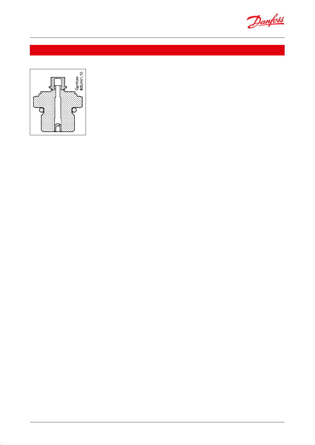
Applications
Figure 1: Pulse-snubber in DST P650
Cavitation, liquid hammer and pressure peaks may occur in liquid lled systems with changes in ow velocity, e.g.
fast closing of a valve or pump starts and stops.
The problem may occur on the inlet and outlet side, even at rather low operating pressures.
The media viscosity has only little eect on the response time. Even at viscosities up to 100 cSt, the response time
will not exceed 4 ms.
© Danfoss | Climate Solutions | 2021.12 AI399437005289en-000101 | 2
Page 3

Accuracy (incl. nonlinearity, hysteresis and repeatability)
± 0.5% FS
Total error band [TEB]
-20 to 100°C: ≤ ± 2% FS
-40 to 125°C: ≤ ± 3% FS
Response time liquids (10 – 90%)
2 ms
Durability, P: 10 – 90% FS
>10 × 10⁶ cycles
Nominal pressure [bar]
4050100
160
250
400
500
Overload pressure
120
150
300
480
750
1200
1500
Burst pressure
800
1000
1600
1600
2500
2500
2500
Nom. output signal (Short-circuit protected)
10 – 90% ratiometric
Supply voltage [UB], polarity protected
5 V ± 0.5 V
Supply – current consumption
4.5 mA
Output impedance
10 Ω DC
Load [RL] (connected to 0 V )
RL ≥ 5 kΩ
Load [RL] (connected to + V )
RL ≥ 5 kΩ
Media temperature range
- 40 – 125 °C
Ambient temperature range
See page Electrical connections
Compensated temperature range
- 40 – 125 °C
Storage temperature range
-55 – 150 °C
EMC – Emission
EN 61326-2-3
EMC Directive
2014/30/EU
EMC – Immunity RF eld
100 V/m
ISO 11452-2
Vibration stability
20Grms, 20-2000Hz
IEC 60068-2-64
Shock resistance
1000G
EN 60068-2-27
Enclosure (depending on electrical connection)
See page Electrical connections
Materials
Wetted parts
Stainless steel
Enclosure
Stainless steel and plastic
Pressure connection
Stainless steel
Electrical connection
See page Electrical connections
OEM Pressure Transmitters for heavy-duty applications, type DST P600, P607 and DST P650
Product Specication
Technical data
Table 1: Performance (EN 60770)
Table 2: Overload and burst pressure
NOTE:
Reachable burst pressure can degrade depending on selected pressure connection, used mounting torque &
counter part material. See Table 8: Dimensions / Combinations
Table 3: Electrical specications
Table 4: Environmental conditions
Table 5: Mechanical conditions
© Danfoss | Climate Solutions | 2021.12 AI399437005289en-000101 | 3
Page 4

Type codeC1C2C3C7
M12x1 EN60947-5-2
Round Packard
Metri-Pack
Deutsch DT04-4P
Deutsch DT04-3P
3
1
24
Key
C
B
A
2 3
1 4
A
C
Ambient temperature,
ratiometric 10 – 90%
- 40 – 125 °C
- 40 – 125 °C
- 40 – 125 °C
- 40 – 125 °C
Enclosure
(IP protection fullled
together with mating
connector)
IP67
IP67
IP67
IP67
Material
SS, PBT 30% GFR
Gold (Au) plated
Glass lled PBT 30%
GFR Tin (Sn) plated
Glass lled PBT 30%
GFR Gold (Au) plated
Glass lled PBT 30%
GFR Tin (Sn) plated
Electrical connections,
ratiometric 10 – 90%
Pin 1: + supply
Pin 2: output
Pin 3: ÷ supply
Pin 4: do not connect
Pin A: ÷ supply
Pin B: + supply
Pin C: output
Pin 1: ÷ supply
Pin 2: + supply
Pin 3: do not connect
Pin 4: output
Pin A: + supply
Pin B: ÷ supply
Pin C: output
Type codeC1C2C3C7
M12 × 1 EN60947-5-2
Round Packard
Metri-Pack
Deutsch DT04-4P
Deutsch DT04-3P
18.3
28.4
M12 x 1
21.2
11.5
20
38.7
22.3
38
40
13.4
37.7
41
25
Type code
BD08
BD11
FA08
GB04
Recommended torque
(1)
22 - 25 Nm
27 - 30 Nm
31 - 35 Nm
35 - 38 Nm
HEX is 22 mm across ats.
11
1.8
5.7
7
⁄16 – 20 UNF-2A
12
2.5
5.7
9/16-18 UNF-2A
11 2.5
5.7
M14x1.5 per ISO 6149-2
12
2
5.7
G
1
⁄4 A ISO 1179-2 (DIN3852-E)
OEM Pressure Transmitters for heavy-duty applications, type DST P600, P607 and DST P650
Electrical connections
Table 6: Electrical connections
Dimensions / Combinations
Table 7: Dimensions / Combinations
Table 8: Dimensions / Combinations
(1)
(1)
Depends on
Depends on
For other combinations please contact Danfoss
© Danfoss | Climate Solutions | 2021.12 AI399437005289en-000101 | 4
NOTE:
dierent parameters such as seal ring, mating material, thread lubrication and pressure level.
dierent parameters such as seal ring, mating material, thread lubrication and pressure level.
Page 5

DST P6..
1
–
–
Standard
0 0
Gasket
With pulse-snubber
Cleanliness ISO 15001
5 0
0 7
–
Measuring range
1
) (Gauge)
Pressure connections (HEX 22 mm)
G B 0 4
0 –
40 bar
2 6
0 –
50 bar
2 7
B D 0 8
⁄ – 20 UNF-2A 2)
0 – 100 bar
3 0
B D 1 1
9/16-18 UNF-2A
0 – 160 bar
3 2
F A 0 8
M14*1,5 ISO6149-2
0 – 250 bar
3 4
0 – 400 bar
3 6
0 – 500 bar
3 7
Electrical connections
C 1
M12 × 1 EN60947-5-2
Pressure reference
C 2
Round Packard Metri-Pack
Gauge(relative) 1
C 3
Deutsch DT04-4P
Output signal
C 7
Deutsch DT04-3P
1
)
For pressure range < 40 bar or >500 bar,
please contact Danfoss
2
) Incl. FKM gasket. Min. medium temperature is -25 °C
Ratiometric, 10 – 90%
6
2
)
2
)
Defined by type
of pressure connection
G ¼ A DIN ISO1179-2 (DIN3852-E)2)
OEM Pressure Transmitters for heavy-duty applications, type DST P600, P607 and DST P650
Ordering
Ordering standard
Figure 2: Ordering standard
© Danfoss | Climate Solutions | 2021.12 AI399437005289en-000101 | 5
Page 6

OEM Pressure Transmitters for heavy-duty applications, type DST P600, P607 and DST P650
Certicates, declarations and approvals
The list contains all certicates, declarations, and approvals for this product type. Individual code number may have
some or all of these approvals, and certain local approvals may not appear on the list.
Some approvals may change over time. You can check the most current status at danfoss.com or contact your local
Danfoss representative if you have any questions.
Approvals
• CE
• RoHS
• MTTFd >100 years
UL recognized File E494625
Conditions of Acceptability – when installed in the nal use equipment, etc., the following are among the
considerations to be made:
• To be Powered by a Class 2 Source, or similar
• Supply voltage and current rating see Product Specication
• MWP (max working pressure) see Product Specication
• Altitude up to 8000 meters
• Medium and ambient temperatures see Product Specication
• Maximum relative humidity 95% non-condensing
• Evaluated for Pollution Degree 2
• Class 2 Device Wiring Only
Technical assistance may be obtained from Danfoss Sensing Solutions, DK 6430 Nordborg – Denmark
© Danfoss | Climate Solutions | 2021.12 AI399437005289en-000101 | 6
Page 7

Online support
Danfoss oers a wide range of support along with our products, including digital product information, software,
mobile apps, and expert guidance. See the possibilities below.
The Danfoss Product Store
The Danfoss Product Store is your one-stop shop for everything product related—no matter where
you are in the world or what area of the cooling industry you work in. Get quick access to essential
information like product specs, code numbers, technical documentation, certications, accessories,
and more.
Start browsing at store.danfoss.com.
Find technical documentation
Find the technical documentation you need to get your project up and running. Get direct access to
our ocial collection of data sheets, certicates and declarations, manuals and guides, 3D models
and drawings, case stories, brochures, and much more.
Start searching now at www.danfoss.com/en/service-and-support/documentation.
Danfoss Learning
Danfoss Learning is a free online learning platform. It features courses and materials specically
designed to help engineers, installers, service technicians, and wholesalers better understand the
products, applications, industry topics, and trends that will help you do your job better.
Create your Danfoss Learning account for free at www.danfoss.com/en/service-and-support/learning.
Get local information and support
Local Danfoss websites are the main sources for help and information about our company and
products. Find product availability, get the latest regional news, or connect with a nearby expert—all
in your own language.
Find your local Danfoss website here: www.danfoss.com/en/choose-region.
Spare Parts
Get access to the Danfoss spare parts and service kit catalog right from your smartphone. The app
contains a wide range of components for air conditioning and refrigeration applications, such as
valves, strainers, pressure switches, and sensors.
Download the Spare Parts app for free at www.danfoss.com/en/service-and-support/downloads.
Any information, including, but not limited to information on selection of product, its application or use, product design, weight, dimensions, capacity or any other
technical data in product manuals, catalogues descriptions, advertisements, etc. and whether made available in writing, orally, electronically, online or via download,
shall be considered informative, and is only binding if and to the extent, explicit reference is made in a quotation or order conrmation. Danfoss cannot accept any
responsibility for possible errors in catalogues, brochures, videos and other material. Danfoss reserves the right to alter its products without notice. This also applies to
products ordered but not delivered provided that such alterations can be made without changes to form, t or function of the product. All trademarks in this material
are property of Danfoss A/S or Danfoss group companies. Danfoss and the Danfoss logo are trademarks of Danfoss A/S. All rights reserved.
© Danfoss | Climate Solutions | 2021.12 AI399437005289en-000101 | 7
 Loading...