

Page 1
Data sheet
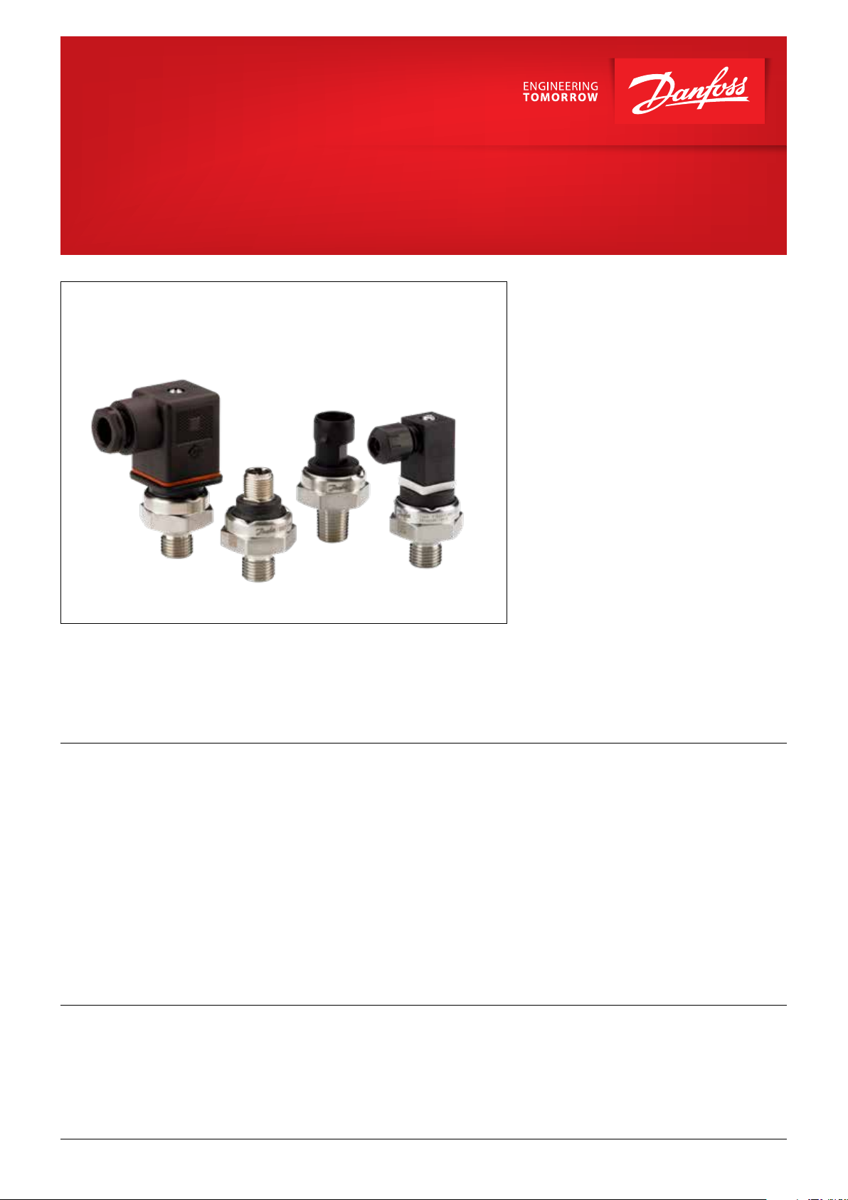
Modular pressure transmitters for harsh environments
DST P500, DST P507 and DST P550
The P500 / P507 / P550 utilizes the thin film
strain gauge sensing technology, incorporating
an hermetically sealed design with no
internal sealing required. Designed for harsh
environments, a rugged 304 stainless
steel housing surrounds the P500 / P507 / P550
transducer.
The P500 / P507 /P550 small, compact design as
well as its low overall weight makes it ideal for
applications with spacing and weight limitations.
This easy-to-use sensor is media resistant,
which allows it to be used for a broad range
of liquid and gaseous media. It can be used at
high operating temperatures and has internal
temperature compensation.
Highly reliable, the P500 / P507 / P550 provides
accurate, high pressure measurements every
time.
P507 is suitable in applications where cleanliness
is a must. All transmitter parts in contact with
the medium meet the cleanliness requirements
according to the ISO 15001 standard.
P550 with integrated pulse-snubber is suitable in
applications with severe medium influences like
cavitation, liquid hammer or pressure peaks.
Features
Approvals
© Danfoss | DCS (im) | 2018.11
• Designed for use in harsh industrial
environments
• For media and ambient temperatures from
-30° – 120 °C
• Reverse polarity protected
• Excellent shock and vibration performance
• Outstanding long-term stability and
repeatability
CE Compliance:
EMC directive 2014/30/EU, EN61000-6-2:2005
and EN61326-1:2006
• Compact and light-weight design
• Hermetically sealed to the application
• RoHS conformity
Other:
2011/65/EU ROHS Directive
UL - E494625
EAC
IC.PD.P21.5C.02 | 1
Page 2
Data sheet | Modular pressure transmitters for harsh environments, DST P500, DST P507 and DST P550
Technical data
Performance (EN 60770)
Accuracy @ 25 °C (incl. non-linearity, hysteresis and non-repeatability) ± 0.5% FS
Non-linearity BFSL (conformity) ≤ ± 0.2% FS
Thermal zero point shift ≤ 0.2% FS / 10° K @ 0-80 °C
Thermal span shift ≤ 0.2% FS / 10° K @ 0-80 °C
Non-repeatability ≤ ± 0.1% FS
Durability, P: 10 – 90% FS > 10 × 10
Overload and burst pressure
Nominal pressure [bar] 6 10 16 25 40 60 100 160 250 400 600
Overload pressure 12 20 32 50 80 120 200 320 375 600 900
Burst pressure 60 100 160 200 320 480 600 960 1000 1600 2400
Electrical specifications
Nom. output signal
(short-circuit protected)
4 – 20 mA
0.5-4.5 V DC
Ratiometric
6
cycles
0-5 V DC/0-10 V DC
Supply voltage [U
], polarity protected
B
8 – 30 V DC
5 V DC ± 0.25 V 8-30/14-30 V DC
Supply – power consumption ≤ 600 mW ≤ 25 mW ≤ 600 mW
Overvoltage protection min. 33 V DC min. 6 V DC min. 33 V DC
Short-circuit protection N/A Yes
1)
Yes
1)
Insulation voltage 500 V DC 500 V DC 500 V DC
Reverse polarity protection Yes
Load ≤ (V
- 8 V DC)/0.02 A[Ω] ≥ 4.7 kΩ ≥ 4.7 kΩ
sup
2)
Yes
2)
Yes
2)
Response time ≤5 ms max. to 63% of FS pressure with step change on input
1)
for min. 3 intervals at 5 minutes each
2)
for min. 10 sec. on assigned pins
Environmental conditions
Media temperature range -30 – 120 °C
Ambient temperature range -30 – 100 °C
Storage temperature -30 – 100 °C
Vibration stability Random 20 PSD IEC 60068-2-64
Shock resistance
Enclosure (depending on electrical connection) IP 65 or IP 67, depending on electrical connection
Shock 25 g IEC 60068-2-27
Free fall 1 m IEC 60068-2-3-1
2 | IC.PD.P21.5C.02
Mechanical characteristics
Materials 304 stainless steel (1.4301 / 1.4307)
Net weight (depending on pressure connection) <0.05 kg
© Danfoss | DCS (im) | 2018.11
Page 3

Data sheet | Modular pressure transmitters for harsh environments, DST P500, DST P507 and DST P550
Ordering
DST P 5 – –
Standard ··············································
Cleanliness according to ISO 15001
With pulse-snubber ·························
00
07
50
Measuring range
0 – 6 bar ······························································-···
0 – 10 bar ·································································
0 – 16 bar ·····························································-··
0 – 25 bar ······························································-·
0 – 40 bar ······························································-···
0 – 60 bar ······························································-···
0 – 100 bar ······························································-···
0 – 160 bar ······························································-···
0 – 250 bar ······························································-···
0 – 400 bar ··································································
0 – 600 bar ······························································-···
Others ······························································-··· ··· ···
Gauge (relative) ·········································································
18
20
22
24
26
28
30
32
34
36
38
99
·······
GB04
·······
AD10
·······
AD08
·······
GB06
······
99
Electrical connection
Figures refer to plug
and standard Pin figuration see page 5
·······
A0
C5
E3
1
C2
99
EN 175301-803-A - male (18 mm)
EN 175301-803-C-male (9.4 mm)
·······
·······
M12 - 4 pin
·······
Packard Metri-Pack 150
·······
Others
External Seal Ring
None
0
Fluorocarbon FKM>-20 °C (Viton)
1
9
Others
Pressure connection
G ¼ A DIN 3852-E
⁄ - 20 UNF-2B (female)
⁄ - 20 UNF-2A (male)
G ¼ A DIN 3852-A
Others, please specify
1)
2)
1)
Mating connector can be ordered, code no.: 060G0008
2)
Mating connector can be ordered, code no.: 063G0306
For other variants please contact Danfoss
1
6
2
5
9
···············
···············
···············
···············
··············
Output signal
4 – 20 mA
0.5 – 4.5 V DC Ratio Metric
0 – 5 V DC
0 –10 V DC
Others, please specify
© Danfoss | DCS (im) | 2018.11
IC.PD.P21.5C.02 | 3
Page 4

Data sheet | Modular pressure transmitters for harsh environments, DST P500, DST P507 and DST P550
Danfoss
090GU42
Danfoss
090GU43
Danfoss
090GU46
Danfoss
090GU47
Dimensions/Combinations
Type code A0 C5 C2 E3
Electrical connection 18 mm DIN 175301-803A 9.4 mm DIN 175301-803C Round Packard Metri-Pack M12
Danfoss
090GU53
Danfoss
090GU49
37
32
Type: DST P500
Datecode: XXXX
Type: DST P500
Datecode: XXXX
Danfoss
090GU44
33
Type: DST P500
Datecode: XXXX
Type: DST P500
Datecode: XXXX
Danfoss
090GU51
34
17
G¼ – DIN 3852-E
External thread
Type code
27 mm
14
⁷⁄₁₆ – 20 UNF-2A
SAE J1926-2
External thread
G¼ – DIN 3852-A
External thread
14
⁷⁄₁₆ – 20 UNF-2B
SAE J1926-1
Internal thread
GB06 AD10 AD08 GB04
Recommended torque 20 Nm 20 Nm 20 Nm 20 Nm
14
4 | IC.PD.P21.5C.02
© Danfoss | DCS (im) | 2018.11
Page 5

Data sheet | Modular pressure transmitters for harsh environments, DST P500, DST P507 and DST P550
P2
P4
P1
P3
P2 P3
P2
P3
Electrical connections
Type code E3 A0 C2 C5
P3
Danfoss
1 2
090GU45
P1
-30 – 100 °C
P2
Round Packard
Metri-Pack
Danfoss
090GU52
27
EN 175301-803-C
9.4 mm
4 – 20 mA
0.5-4.5 V DC
Ambient
Ratiometric
temperature
0-5 V DC
0-10 VDC
Enclosure (IP protection fulfilled
together
with mating connector)
P1
Danfoss
090GU50
27
P4
4 3
EN 175301-803-A,
M12, 4 pin
18 mm
IP67 IP65 IP67 IP65
Danfoss
090GU48
27
P1P4
Materials
Electrical
connection
4 – 20 mA
(2 wire)
0.5-4.5 V DC
Ratiometric
0-5 V DC,
0-10 V DC
Tin plated on Nickel,
Nylon 66, 40% Glass
Pin1: + supply
Pin 2: not used
Pin 3:÷ supply
Pin 4: not used
Pin 1: + supply
Pin 2: not used
Pin 3: + output
Pin 4: ÷ common
Pin 1: + supply
Pin 2: not used
Pin 3: + output
Pin 4: ÷ common
Tin plated on Nickel,
Nylon 66, 40% Glass
Pin 1: + supply
Pin 2: ÷ supply
Pin 3: not used
Pin 4: not used
Pin 1: + supply
Pin 2: + output
Pin 3: ÷ common
Pin 4: not used
Pin 1: + supply
Pin 2: + output
Pin 3: ÷ common
Pin 4: not used
Tin plated on Nickel,
Zytel 33% Glass
Pin1: ÷ supply
Pin 2: + supply
Pin 3: not used
Pin 1 ÷ common
Pin 2: + supply
Pin 3: + output
Pin 1 ÷ common
Pin 2: + supply
Pin 3: + output
Tin plated on Nickel,
Nylon 66, 40% Glass
Pin 1: + supply
Pin 2: ÷ supply
Pin 3: not used
Pin 4: not used
Pin 1: + supply
Pin 2: + output
Pin 3: ÷ common
Pin 4: not used
Pin 1: + supply
Pin 2: + output
Pin 3: ÷ common
Pin 4: not used
© Danfoss | DCS (im) | 2018.11
IC.PD.P21.5C.02 | 5
Page 6

© Danfoss | DCS (im) | 2018.11 IC.PD.P21.5C.04 | 6
 Loading...