

Page 1
Data Sheet
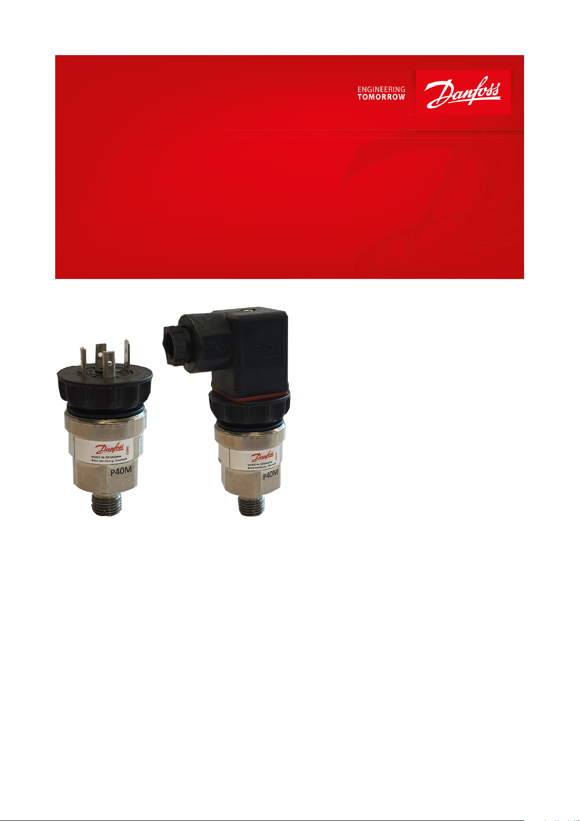
Pressure transmitters
Type DST P40M
Harsh environment marine application
The P40M pressure transmitter has been
designed specic for pressure monitoring of
marine applications such as Ballast water
treatment systems, Exhaust gas scrubbers,
Desalination and Sea water cooling systems
where high corrosion resistance and longevity
are essential for the continued operation of
auxiliary & propulsion systems onboard the
vessel.
The enclosure of the pressure transmitter is
machined out from a single piece of Titanium
to eliminate any structural weaknesses.
Titanium is exceptionally resistant to a broad
range of acids and alkalis, as well as Sodium
Chloride and polluted waters. Titanium’s
corrosion resistance together with its low
density, high strength and erosion resistance,
make this pressure transmitter ideal for
numerous chemical processing and marine
uses.
The pressure sensing element is made from
ceramic Al2O3 96% which has excellent
chemical immunity and is suitable for nearly all
aggressive media. The pressure transmitter
works following the piezo resistive principle
and the Wheatstone bridge is screen printed
directly on one side of the ceramic diaphragm
by means of Thick Film technology
AI366043639180en-000402
Page 2

Pressure transmitters, type DST P40M
Features
• Designed for use in corrosive industrial environments such as desalination systems, medical industry, chemical
processing, chlorate containing liquids, hydro-carbon processing, etc.
• Enclosure Titanium grade 2
• Temperature compensated
• Reverse polarity protected
• Gauge (relative)
• Wetted parts: Titanium & Ceramic
• Ceramic Al2O3 96%
• High linearity and low hysteresis value
• RoHS compliance
© Danfoss | Climate Solutions | 2021.06 AI366043639180en-000402 | 2
Page 3
Specications
Values
Transmitter type
DST P40M
Accuracy (incl. non-linearity, hysteresis and repeatability)
< ± 1% FS (typ.) @ ambient temperature
Compensated temperature range
0 – 80 °C
Total error band within compensated temperature range
± 1.5% FS (typ.)
Output type
4 – 20 mA
Pressure reference
Gauge
Supply voltage range
9 – 32 V DC
Rise time (10 – 90%)
< 5 ms
Overload pressure
2 x FS
Burst pressure
2.5 x FS
Durability
P:10-90%FS > 10 mio cycles
Media temperature range
-15 – 85 °C
Ambient temperature range
Depending on electrical connection see Electrical connections
Storage temperature range
-40 – 105 °C
Load [RL]
RL≤(UB-8V)/0,02A
EMC – Emission
EN 61000-6-3
EMC – Immunity
EN 61000-6-2
Vibration stability
Sinusoidal
15.9 mm-pp, 5 Hz – 25 Hz
IEC 60068-2-6
20 g, 25 Hz – 2 kHz
Shock resistance
Shock
100 g / 1 ms
IEC 60068-2-27
0 – 4 bar
Gauge
0 – 6 bar
Gauge
0 – 10 bar
Gauge
0 – 16 bar
Gauge
0 – 25 bar
Gauge
0 – 100 bar
Sealed gauge
Type code
A0: Male
A1: Pg 9
A6: Pg 11
A9: Pg 13.5
EN 175301-803-A, Pg 9
Ambient temperature
-25 - 85 °C
Enclosure (IP protection
fullled together with mating connector)
IP65
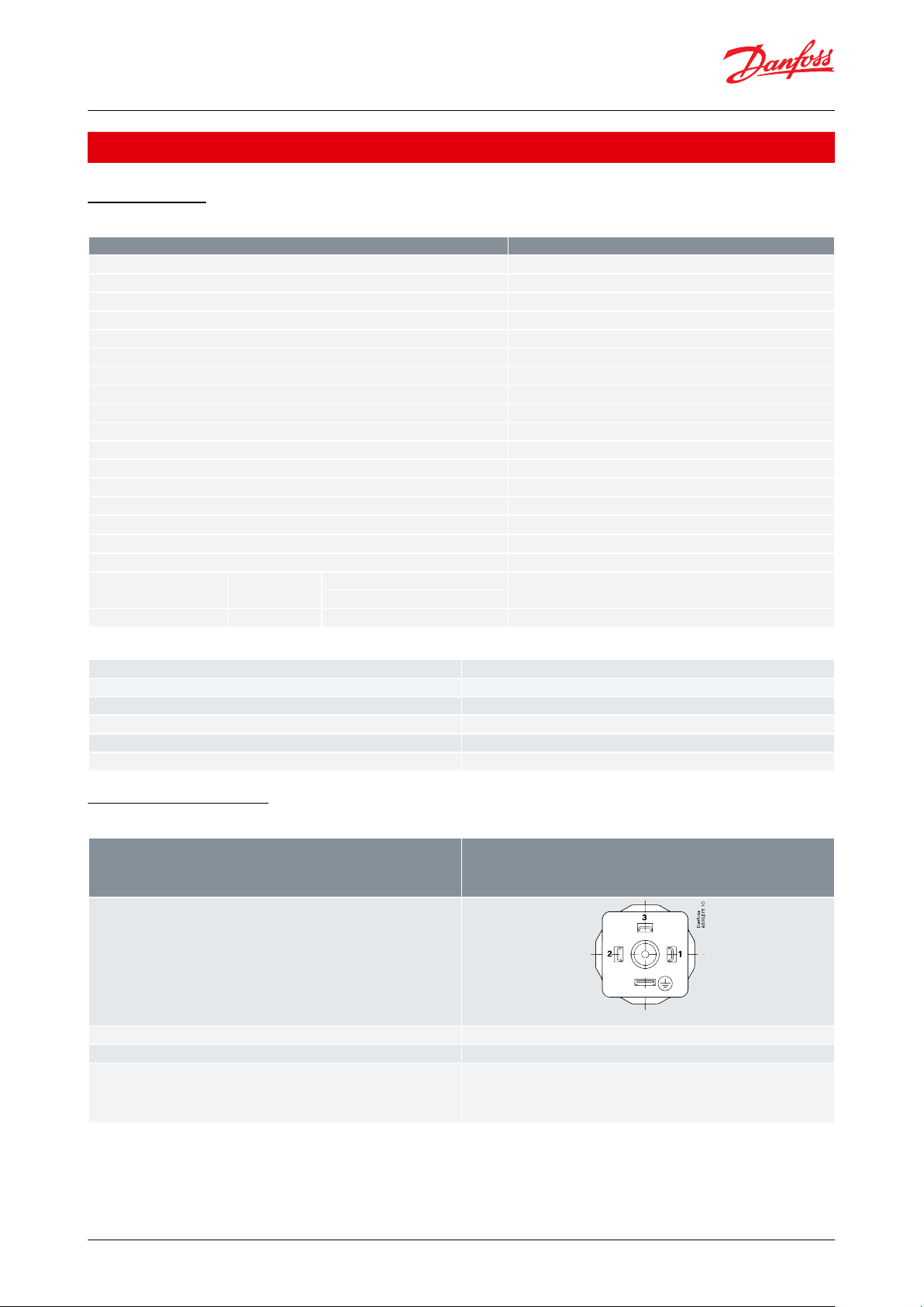
Electrical connection, 4 – 20 mA output (2 wire)
Pin 1: + supply
Pin 2: ÷ supply
Pin 3: not used
Pin 4: Ground connection to sensor house
Pressure transmitters, type DST P40M
Product specication
Technical data
Table 1: Technical specications
Table 2: Pressure range
Electrical connections
Table 3: Electrical connections
© Danfoss | Climate Solutions | 2021.06 AI366043639180en-000402 | 3
Page 4

Type code
A1A6A9
Connector
Danfoss
93Z276
34.8 ± 2
~39
EN 175301-803-A, Pg 9
Danfoss
93Z276
34.8 ± 2
~39
EN 175301-803-A, Pg 11
Danfoss
60G254
44
71
EN 175301-803-A, Pg 13.5
Hex 27h13
13 ± 0.3
Ø37.5 ± 0.3
Ø30.6 ± 0.3
48.6 ± 0.2
Danfoss
93Z275
Connection Types
Type
G
1
⁄4”; ISO 1179-2
G
1
⁄2"; ISO 1179-2
Gasket
FKM
FKM
Type code
GB04
GB08
Recommended torque
(1)
30 – 35 Nm
30 – 35 Nm
Pressure transmitters, type DST P40M
Dimensions / Combinations
Table 4: Dimensions and combinations of connector and connection types
(1)
(1)
© Danfoss | Climate Solutions | 2021.06 AI366043639180en-000402 | 4
Depends on dierent parameters such as gasket material, mating material, thread lubrication and pressure level
Depends on dierent parameters such as gasket material, mating material, thread lubrication and pressure level
Page 5

DST P40M-
– –
0
No Gasket
1
Gasket (ISO 1179-2) FKM
Measuring range
GB0 4
G ¼" (ISO 1179-2)
GB0 8
G½" (ISO 1179-2)
0 –
4.0 bar
1 6
0 –
6.0 bar
1 8
0 –
10 bar
2 0
0 –
16 bar
2 2
A0
No female plug (EN 175301-803)
0 –
25 bar
2 4
A1
Plug (EN 175301-803-A) Pg 9
0 –
100 bar
3 0
A6
Plug (EN 175301-803-A) Pg 11
A9
Plug (EN 175301-803-A) Pg 13,5
1
4 – 20 mA
Pressure reference
Gauge (relative) 1
Danfoss
93Z277
Pressure transmitters, type DST P40M
Ordering
Ordering standard
Non-standard build-up combinations may be selected. However, minimum order quantities may apply.
Please contact your local Danfoss oce for further information or request on other versions.
© Danfoss | Climate Solutions | 2021.06 AI366043639180en-000402 | 5
Page 6

File name
Document type
Document topic
Approvals Authority
MRA000003B
Approval Certicate
Marine classication (EU RO) MUTUAL
RECOGNITION CERTIFICATE
DNV
DLN34014-AE005
Approval Certicate
Marine classication
Korean Register
CPH04967-AE014
Approval Certicate
Marine classication
Korean Register
21A003
Approval Certicate
Marine classication
NKK-Approval Certicate
Marine classication
CCS (Pending)
Pressure transmitters, type DST P40M
Certicates, declarations, and approvals
The list contains all certicates, declarations, and approvals for this product type. Individual code number may have
some or all of these approvals, and certain local approvals may not appear on the list.
Some approvals may change over time. You can check the most current status at danfoss.com or contact your local
Danfoss representative if you have any questions.
© Danfoss | Climate Solutions | 2021.06 AI366043639180en-000402 | 6
Page 7

Online support
Danfoss oers a wide range of support along with our products, including digital product information, software,
mobile apps, and expert guidance. See the possibilities below.
The Danfoss Product Store
The Danfoss Product Store is your one-stop shop for everything product related—no matter where
you are in the world or what area of the cooling industry you work in. Get quick access to essential
information like product specs, code numbers, technical documentation, certications, accessories,
and more.
Start browsing at store.danfoss.com.
Find technical documentation
Find the technical documentation you need to get your project up and running. Get direct access to
our ocial collection of data sheets, certicates and declarations, manuals and guides, 3D models
and drawings, case stories, brochures, and much more.
Start searching now at www.danfoss.com/en/service-and-support/documentation.
Danfoss Learning
Danfoss Learning is a free online learning platform. It features courses and materials specically
designed to help engineers, installers, service technicians, and wholesalers better understand the
products, applications, industry topics, and trends that will help you do your job better.
Create your Danfoss Learning account for free at www.danfoss.com/en/service-and-support/learning.
Get local information and support
Local Danfoss websites are the main sources for help and information about our company and
products. Find product availability, get the latest regional news, or connect with a nearby expert—all
in your own language.
Find your local Danfoss website here: www.danfoss.com/en/choose-region.
Spare Parts
Get access to the Danfoss spare parts and service kit catalog right from your smartphone. The app
contains a wide range of components for air conditioning and refrigeration applications, such as
valves, strainers, pressure switches, and sensors.
Download the Spare Parts app for free at www.danfoss.com/en/service-and-support/downloads.
Any information, including, but not limited to information on selection of product, its application or use, product design, weight, dimensions, capacity or any other
technical data in product manuals, catalogues descriptions, advertisements, etc. and whether made available in writing, orally, electronically, online or via download,
shall be considered informative, and is only binding if and to the extent, explicit reference is made in a quotation or order conrmation. Danfoss cannot accept any
responsibility for possible errors in catalogues, brochures, videos and other material. Danfoss reserves the right to alter its products without notice. This also applies to
products ordered but not delivered provided that such alterations can be made without changes to form, t or function of the product. All trademarks in this material
are property of Danfoss A/S or Danfoss group companies. Danfoss and the Danfoss logo are trademarks of Danfoss A/S. All rights reserved.
© Danfoss | Climate Solutions | 2021.06 AI366043639180en-000402 | 7
 Loading...