

Page 1
Data sheet
Pressure transmitter for marine applications
DST P30M
The compact high temperature pressure
transmitter is designed for use in almost all
marine applications, and offers a reliable pressure
measurement, even under harsh environmental
conditions.
The flexible pressure transmitter program covers
different output signals, absolute or gauge
(relative) versions, measuring ranges from 0 – 1
to 0 – 600 bar and a wide range of pressure and
electrical connections.
A robust design, an excellent vibration stability,
and a high degree of EMC / EMI protection
equip the pressure transmitter to meet the most
stringent marine requirements.
Running a powerful ARM-based microcontroller,
the DST P30M offers diagnostic functions and
performance features.
Features
Approvals
• Designed for use in severe maritime
environments
• Robust electronic platform for harsh electrical
environments
• Available output signals:
- 10 - 90% of supply voltage
- 4 - 20 mA
- Absolute voltage
• For media temperatures up to 125 °C
Det Norske Veritas/Germanisher Lloyd, DNV GL
LLoyds Register of Shipping, LR
Bureau Veritas; BV
Registro Italiana Navale, RINA
• A wide range of pressure and electrical
connections
• Enclosure and wetted parts of AISI 316L
• For use in Zone 2 explosive atmospheres
• Fully digitally compensated
• Diagnostic functions and scalable performance
features available
• UL approved
Nippon Kaiji Kyokai, NKK
American Bureau of Shipping, ABS
Korean Register of Shipping, KR
China Classification Society, CCS
Russian Maritime Register of Shipping, RMRS
© Danfoss | DCS | 2021.03
AI368009388819en-000101| 1
Page 2
Data sheet | Pressure transmitter for marine applications, DST P30M
Full scale (%)
01
Full scale (%)
Application and media
conditions
Pulse-snubber
Technical data
Application
Cavitation, liquid hammer and pressure peaks
may occur in liquid filled hydraulic systems with
changes in flow velocity, e.g. fast closing of a
valve or pump starts and stops.
The problem may occur on the inlet and outlet
side, even at rather low operating pressures.
Media condition
Clogging of the nozzle may occur in liquids
containing particles. Mounting the transmitter
in an upright position minimizes the risk of
clogging, because the flow in the nozzle is
limited to the start-up period until the dead
volume behind the nozzle orifice is filled.
The media viscosity has only little effect on the
response time. Even at a viscosities up to
100 cSt, the response time will not exceed 4 ms.
Performance (EN 60770)
Accuracy @ 20 ºC ≤ ± 1% FS
Response time
Overload pressure (static) 6 × FS (max. 1500 bar)
Burst pressure 6 × FS (max. 2000 bar)
Power-up time < 50 ms
Durability, P: 10 – 90% FS > 10 mil. cycles
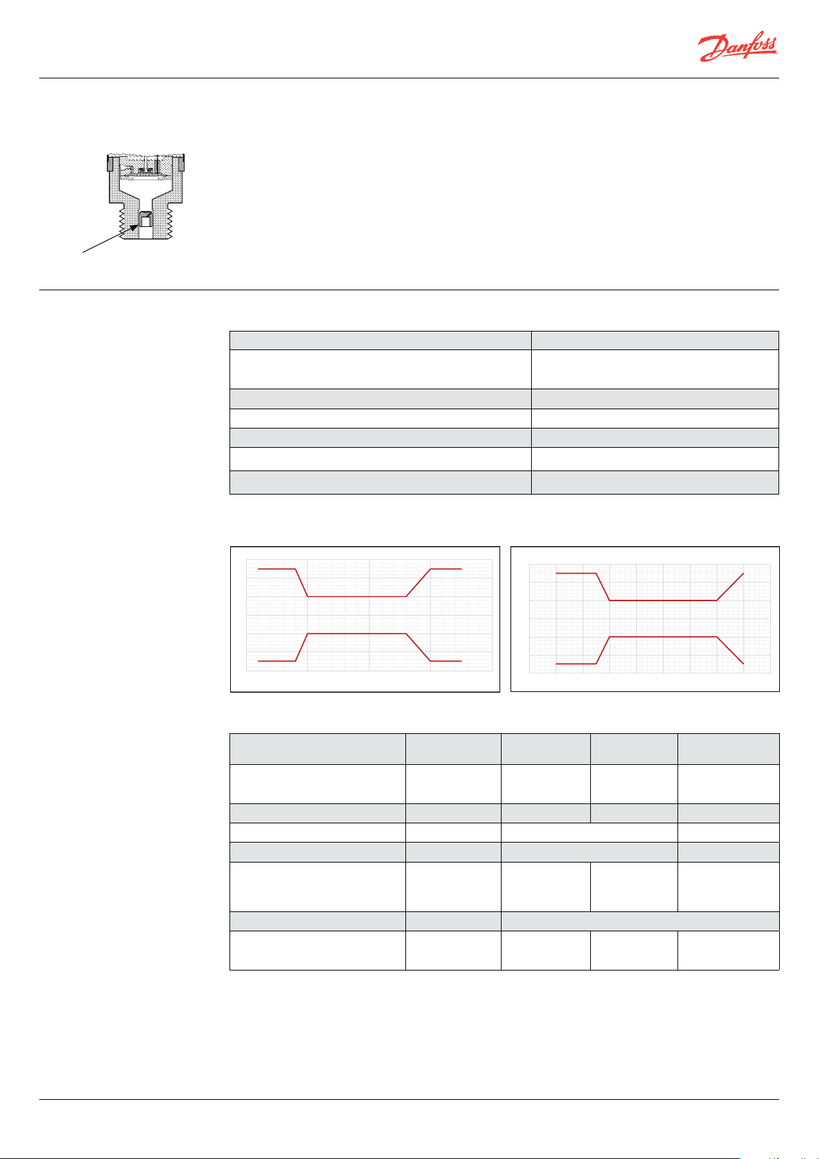
Total Error Band (TEB) Default TEB profile - see graph below
< 2 ms
Progammable fitltering available
mA version ratiometric/absolute voltage version
Danfoss
3
2
1
0
050100 150
-1
-2
-3
Temperature (°C)
60G9060
-60-40 -20020 40 60 80 10
3
2
1
0
-1
-2
-3
Temperature (°C)
Electrical specifications
Nom. output signal
(short-circuit protected)
Supply voltage [U
], polarity protected
B
4 – 20 mA 0 – 5 V, 1 – 5 V, 1– 6 V 0 – 10 V
9 – 32 V DC
(12 / 24 V DC nom.)
9 – 32 V DC
(12 / 24 V DC nom.)
(12 / 24 V DC nom.)
15 – 32 V DC
Supply – current consumption – ≤ 5 mA ≤ 8 mA < 5 mA – 5 V
Supply voltage dependency < 0.1% FS / 10 V < 0.05% FS / 10 V -
Ratiometricity - - < 0.05% FS / 4.5 - 5.5 V
0-5V: 5.75 V
Output limitation 22.4 mA
1-5V: 5.6 V
0-10V: 11.5 V ≈ supply voltage
1-6V: 6.75 V
Sink / Source – < 1 mA
10 – 90% of
supply voltage
4.5 – 5.5 V DC
(5 V DC nom.)
Danfoss
60G9059
20
2 | AI368009388819en-000101
] (load connected to 0 V) RL ≥ (UB- 9 V)/0.02 A RL ≥ 10 kΩ RL ≥ 15 kΩ RL ≥ 10 kΩ at 5 V
Load [R
L
© Danfoss | DCS | 2021.03
Page 3

Data sheet | Pressure transmitter for marine applications, DST P30M
Technical data
(continued)
Environmental conditions
Sensor operating temperature
Media temperature range -40 – 125 °C
EMC – Emission EN 61000-6-3
EMC – Immunity (Output > 1 GHz - deviation < 3%) EN 61000-6-2
Insulation resistance > 100 MΩ at 500 V DC
Vibration stability Random 7.5 g
Shock resistance Shock 500 g / 1 ms IEC 60068-2-27
Enclosure (depending on electrical connection) See page 6
4 - 20 mA -40 – 100 °C
10 - 90% of Vs & abs. voltage -40 – 125 °C
, 5 Hz – 1 kHz IEC 60068-2-64
rms
Explosive atmospheres
Zone 2 applications EN60079-0; EN60079-15
-10 ˚C < Ta < + 85 ˚C
When used in ATEX Zone 2 areas at low temperatures the cable and plug must be protected against impact
Mechanical characteristics
Wetted parts EN 10088-1; 1.4404 (AISI 316 L)
Materials
Net weight (depending on pressure connection and electrical connection) 0.2 – 0.3 kg
Enclosure EN 10088-1; 1.4404 (AISI 316 L)
Electrical connections See page 6
Pressure connections See page 5
Output and diagnostics
Pressure output signal
- Defines the measuring range of the sensor.
Output clamp levels
- Limit the pressure output signal if the
pressure rises above or falls below the normal
range.
Sensor fault signal
- Output at this level signals a sensor fault. The
fault signal setting can be high or low.
Flexible output clamping and flexible fault
signal error level to application fit available.
Contact Danfoss for detailed information and
requirements.
Self-diagnostic default levels
* programmable filtering available
Ratiometric % of
supply voltage
Zero 10% 4mA 0V 1V 1V 0V 1V
FS 90% 20mA 5V 5V 6V 10V 10V
Span 80% 16mA 5V 4V 5V 10V 9V
Output clamp level Lo 4% 3,8mA NA 0,5V 0,5V N/A 0,5V
Output clamp level Hi 99% 20,5mA 5,5V 5,5V 6,5V 11V 11V
Fault signal Lo 2% - - - - - -
Fault signal Hi - 21,5mA 5,8V 5,8V 6,8V 11,5V 11,5V
4-20mA 0-5V 1-5V 1-6V 0-10V 1-10V
© Danfoss | DCS | 2021.03
AI368009388819en-000101| 3
Page 4

Data sheet | Pressure transmitter for marine applications, DST P30M
Ordering standard
DST P30M
Type
Standard 0 0
with pulse-snubber 5 0
– –
A B 0 4
G B 0 4
A B 0 8
C D 2 8
A C 0 4
–
Gasket / O-ring material
0
No gasket
1
Gasket, Viton -20 °C – 125 °C
3
O-ring, Viton -20 °C – 125 °C
Pressure connection
G ¼ A (EN 837)
(only without pulse-snubber)
G ¼ (DIN 3852E)
G ½ A (EN 837)
G ¼ female with flange2)
¼ - 18NPT
Non-standard build-up
combinations may be selected.
However, minimum order
quantities may apply.
Please contact your local
Danfoss office for further
information or request
on other versions.
Measuring range
-1 –
-1 –
4.0 bar
10 bar
1
)
1
)
0 – 1.0 bar
0 – 1.6 bar
0 – 2.5 bar
0 – 4.0 bar
0 – 6.0 bar
0 – 10 bar
0 – 16 bar
0 – 25 bar
0 – 40 bar
0 – 60 bar
0 – 100 bar
0 – 160 bar
0 – 250 bar
0 – 400 bar
0 – 600 bar
1)
Sealed gauge only
2)
Viton gasket for flange and bolts for mounting included
* Gauge versions only available as sealed gauge versions
Preferred versions
8 6 A9
8 8 DG
1 0 A1
1 2 A6
1 4 C8
1 6
1 8 E3
2 0
2 2 Output signal
2 4 1
2 6 2 0 – 5 V
2 8 3 1 – 5 V
3 0 4 1 – 6 V
3 2 5 0 – 10 V
3 4 7 1 – 10 V
3 6
3 8
Pressure reference
1
Gauge (relative)
2
Absolute
Electrical connection
Plug (EN 175301-803-A), Pg 13.5
Cable, screened, 3 m
Plug (EN 175301-803-A), Pg 9
Plug (EN 175301-803-A), Pg 11
Bayonet plug; ISO 15170-A1-3.2-Sn
Cable, screened, 2 m
F4
* EN 60947-5-2, M12 x 1, male excl. female plug
4 – 20 mA
6 Ratiometric, 10 – 90%
4 | AI368009388819en-000101
© Danfoss | DCS | 2021.03
Page 5

Data sheet | Pressure transmitter for marine applications, DST P30M
39.5
34
oss
93Z273
39.5
38
s
93Z274
Dimensions/Combinations
Type code: A1 A6 A9 F4 / DG E3 C8
EN 175301-803-A,
Pg 9
EN 175301-803-A,
Pg 11
EN 175301-803-A,
Pg 13.5
Cable screened ship,
2 m / 3 m
EN 60947-5-2, M12 1,
male excl. female plug
ISO 15170-A1-3.2-Sn, excl
female plug, Bayonet plug
Danf
Danfos
Cartridge design
Block design
G¼ Pressure port
G ¼ A
(EN 837)
G ¼
(DIN 3852-E)
G ½ A
(EN 837)
¼ - 18 NPT G ¼ A female with flange
Type code AB04 GB04 AB08 AC 04 CD28
Recommended
1
torque
)
1
) Depends of different parameters such as gasket material, mating material, thread lubrication and pressure level
30 – 35 Nm 30 – 35 Nm 30 – 35 Nm
2 - 3 turns after
finger tightened
–
© Danfoss | DCS | 2021.03
AI368009388819en-000101| 5
Page 6

Danfoss can accept no responsibility for possible errors in catalogues, brochures and other printed material. Danfoss reserves the right to alter its products without notice. This also applies to products
already on order provided that such alterations can be made without subsequential changes being necessary eady agreed.
All trademarks in this material are property of the respective companies. Danfoss and the Danfoss logotype are trademarks of Danfoss A/S. All rights reserved.
Electrical connections
Type code, See page 5 A1 / A6 / A9 DG F4 E3 C8
Ambient temperature,
4 – 20 mA output
Ambient temperature,
ratiometric output
Enclosure
(IP protection fulfilled together
with mating connector)
Material
Electrical connection,
4 – 20 mA
output (2 wire)
Electrical connection,
ratiometric output
1)
Common
EN 175301-803-A,
Pg 9/11/13.5
Cable screened ship,
3 m
Cable screened ship
2m
EN 60947-5-2
M12 x 1; 4-pin
ISO 15170-A1-3.2-Sn
-40 – 100 °C -30 – 100 °C -30 – 100°C -25 – 90 °C -40 – 100 °C
-40 – 125 °C -30 – 125 °C -30 – 125 °C -25 – 90 °C -40 – 125 °C
IP65 IP67 IP67 IP67 IP67
Glass filled
polyamid, PA 6.6
Pin 1: + supply
Pin 2: ÷ supply
Pin 3: not used
Black wire: + supply
Blue wire: ÷ supply
Brown wire: not used
Screen: Connected
to MBS enclosure
RTFRO with PE
shrinkage tubing
Polylefin cable with
PE Shrinkage tubing
Brown wire: + supply
Black wire: ÷ supply
Red wire: not used
Orange: not used
Screen: not connected
Pin 1: + supply
Pin 2: not used
Pin 3: not used
Pin 4:÷ supply
Nickel plated
brass, CuZn/Ni
polyester PBT
Pin 1: + supply
Pin 2: ÷ supply
Pin 3: not used
Pin 4: not used
to MBS enclosure
Earth: Connected
to MBS enclosure
Pin 1: + supply
Pin 2: ÷ supply
Pin 3: + output
Black wire: + supply
1
)
Blue wire: ÷ supply
Brown wire: + output
Screen: Connected
to MBS enclosure
Red wire: + Supply
1)
Black wire: ÷ Supply
Brown wire: +Output
Orange: Not used
Screen: Not connected
Pin 1: + supply
Pin 2: not used
1)
Pin 3: + output
Pin 4: ÷ supply/
common
Pin 1: + supply
Pin 2: ÷ supply
Pin 3: not used
Pin 4: +output
to MBS enclosure
Earth: Connected
to MBS enclosure
Bayonet
Glass filled
1)
© Danfoss | DCS | 2021.03
AI368009388819en-000101
 Loading...