

Page 1
Data sheet
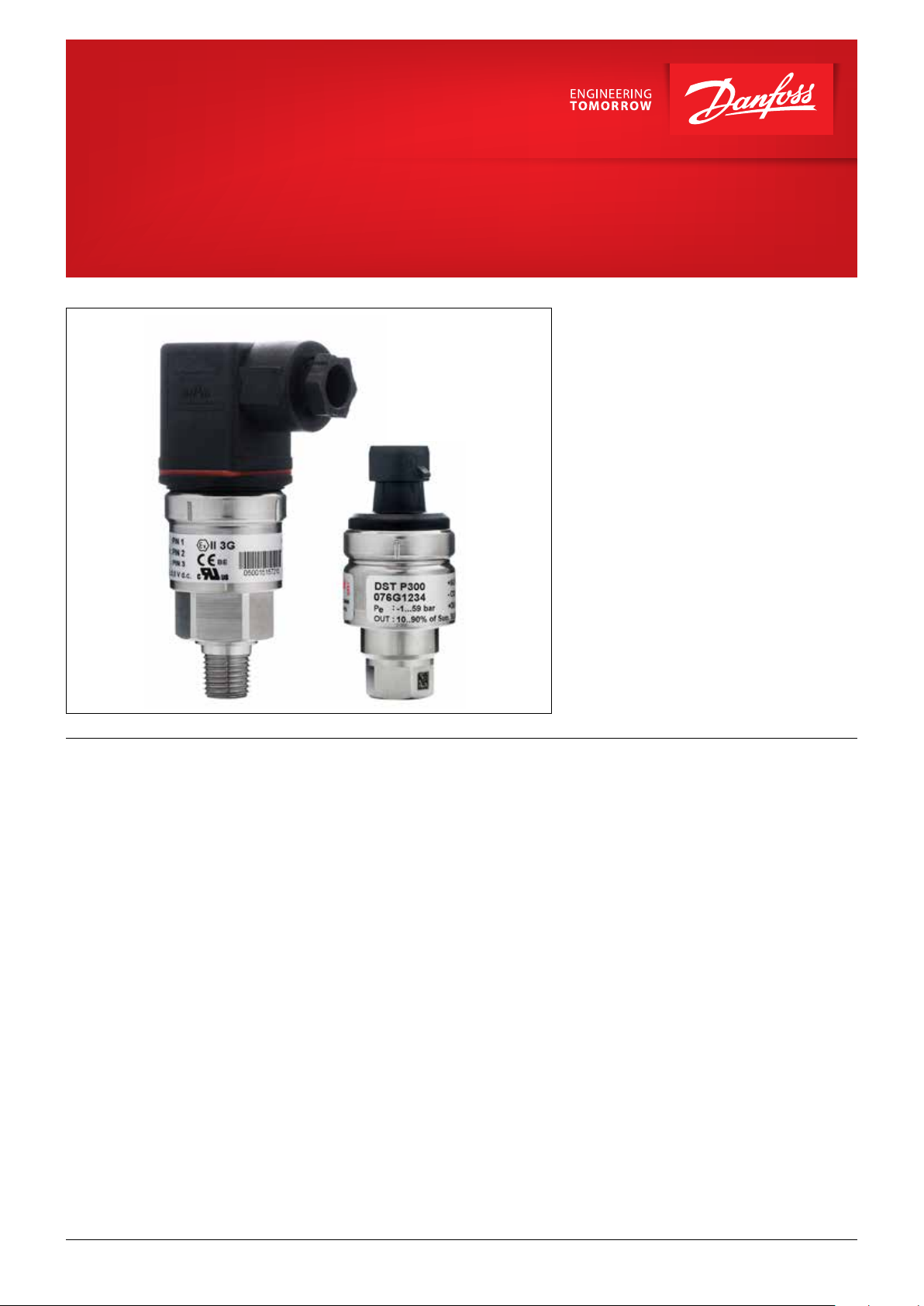
Pressure transmitter for general
industrial purposes with diagnostics
DST P300
The compact high temperature pressure
transmitter is designed for use in almost all
industrial applications, and offers a reliable
pressure measurement, even under harsh
environmental conditions.
The flexible pressure transmitter program covers
different output signals, absolute or gauge
(relative) versions, measuring ranges from 0 – 1
to 0 – 600 bar and a wide range of pressure and
electrical connections.
A robust design with an excellent vibration
stability and a high degree of EMC / EMI
protection equip the pressure transmitter to
meet the most stringent industrial requirements.
Running a powerful ARM-based microcontroller,
the DST P300 offers diagnostic functions and
performance features.
Features • Robust electronic platform for harsh electrical
environments
• Available output signals:
- 10 - 90% of supply voltage
- 4 - 20 mA
- Absolute voltage
• For media temperatures up to 125 °C
• A wide range of pressure and electrical
connections
• Enclosure and wetted parts of AISI 316L
• Fully digitally compensated
• Diagnostic functions
• Scalable performance features available
© Danfoss | DCS (im) | 2021.01
AI366219695189en-000202 | 1
Page 2
Data sheet | Pressure transmitter for industrial applications, DST P300
01
Full scale (%)
01
Application and media
conditions
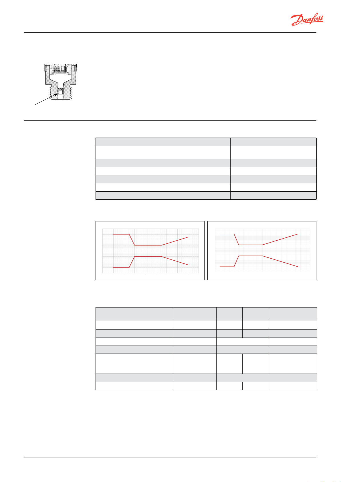
Pulse-snubber
Technical data
Application
Cavitation, liquid hammer and pressure peaks may
occur in liquid filled hydraulic systems with changes in
flow velocity, e.g. fast closing of a valve or pump starts
and stops.
The problem may occur on the inlet and outlet side,
even at rather low operating pressures.
Media condition
Clogging of the nozzle may occur in
liquids containing particles. Mounting
the transmitter in an upright position
minimizes the risk of clogging, because the
flow in the nozzle is limited to the start-up
period until the dead volume behind the
nozzle orifice is filled.
The media viscosity has only little effect
on the response time. Even at a viscosities
up to 100 cSt, the response time will not
exceed 4 ms.
Performance (EN 60770)
Accuracy @ 20ºC ≤ ± 1% FS (max), ≤0,5%FS (typ.)
Total Error Band (incl. non-linearity, hysteresis, repeatability, thermal
error, offset and FS span)
Response time
(1)
(1)
Overload pressure (static) 6 × FS (max. 1500 bar)
Burst pressure 6 × FS (max. 2000 bar)
Power-up time < 50 ms
Durability, P: 10% – 90% FS > 10 mil. cycles
(1)
Programmable filtering available
Default TEB profile - see graph below
< 2 ms
mA version ratiometric/absolute voltage version
Danfoss
4
3
2
1
-60-40 -20020 40 60 80 10
0
-1
-2
-3
-4
Temperature (°C)
60G9057
-50050 10
20
Full scale (%)
4
3
2
1
0
-1
-2
-3
-4
Temperature (°C)
Electrical specifications
Nom. output signal
(short-circuit protected)
Supply voltage [U
], polarity protected 9 – 32 V DC 9 – 32 V DC 15 – 32 V DC 4.5 – 5.5 V DC
B
4 – 20 mA
Supply – current consumption – ≤ 5 mA ≤ 8 mA ≤ 5 mA at 5 V DC
Supply voltage dependency < 0.1% FS / 10 V < 0.05% FS / 10 V --
Ratiometricity - - < 0.05% FS / 4.5 - 5.5 V
Output limitation 22.4 mA
Sink / Source –
] (load connected to 0 V) RL ≤ (UB- 9V) / 0.02 A RL ≥ 10 kΩ RL ≥ 15 kΩ RL ≥ 10 kΩ at 5 V DC
Load [R
L
0 – 5, 1 – 5,
1– 6 V
0-5V: 5.75 V
1-5V: 5.6 V
1-6V: 6.75 V
0 – 10 V,
1 – 10 V
Ratiometric
10 – 90% of [UB]
0-10V: 11.5 V ≈ supply voltage
< 1 mA
Danfoss
60G9058
50
2 | AI366219695189en-000202
© Danfoss | DCS (im) | 2021.01
Page 3
Data sheet | Pressure transmitter for industrial applications, DST P300
Technical data
(continued)
Environmental conditions
Sensor operating temperature
Media temperature range -40 – 125 °C
Ambient temperature See page 6
EMC – Emission EN 61000-6-3
EMC – Immunity (Output > 1 GHz - deviation < 3%) EN 61000-6-2
Insulation resistance > 100 MΩ at 500 V DC
Vibration stability Random 7.5 g
Shock resistance Shock 500 g / 1 ms IEC 60068-2-27
Enclosure (depending on electrical connection) See page 6
1)
O perating temperature is a resu lt of influence from media temp erature, ambient tempe rature and self-heating contr ibution from the
internal electronics.
1)
4 - 20 mA -40 – 100 °C
10 - 90% of Vs and abs. voltage -40 – 125 °C
, 5 Hz – 1 kHz IEC 60068-2-64
rms
Explosive atmospheres
Zone 2 applications EN60079-0; EN60079-15; EN60079-7
-10 ˚C < Ta < + 85 ˚C
When used in ATEX Zone 2 areas at low temperatures the cable and plug must be protected against impact
Mechanical characteristics
Wetted parts EN 10088-1; 1.4404 (AISI 316 L)
Materials
Net weight (depending on pressure connection and electrical connection) 0.2 – 0.3 kg
Enclosure EN 10088-1; 1.4404 (AISI 316 L)
Electrical connections See page 6
Pressure connections See page 5
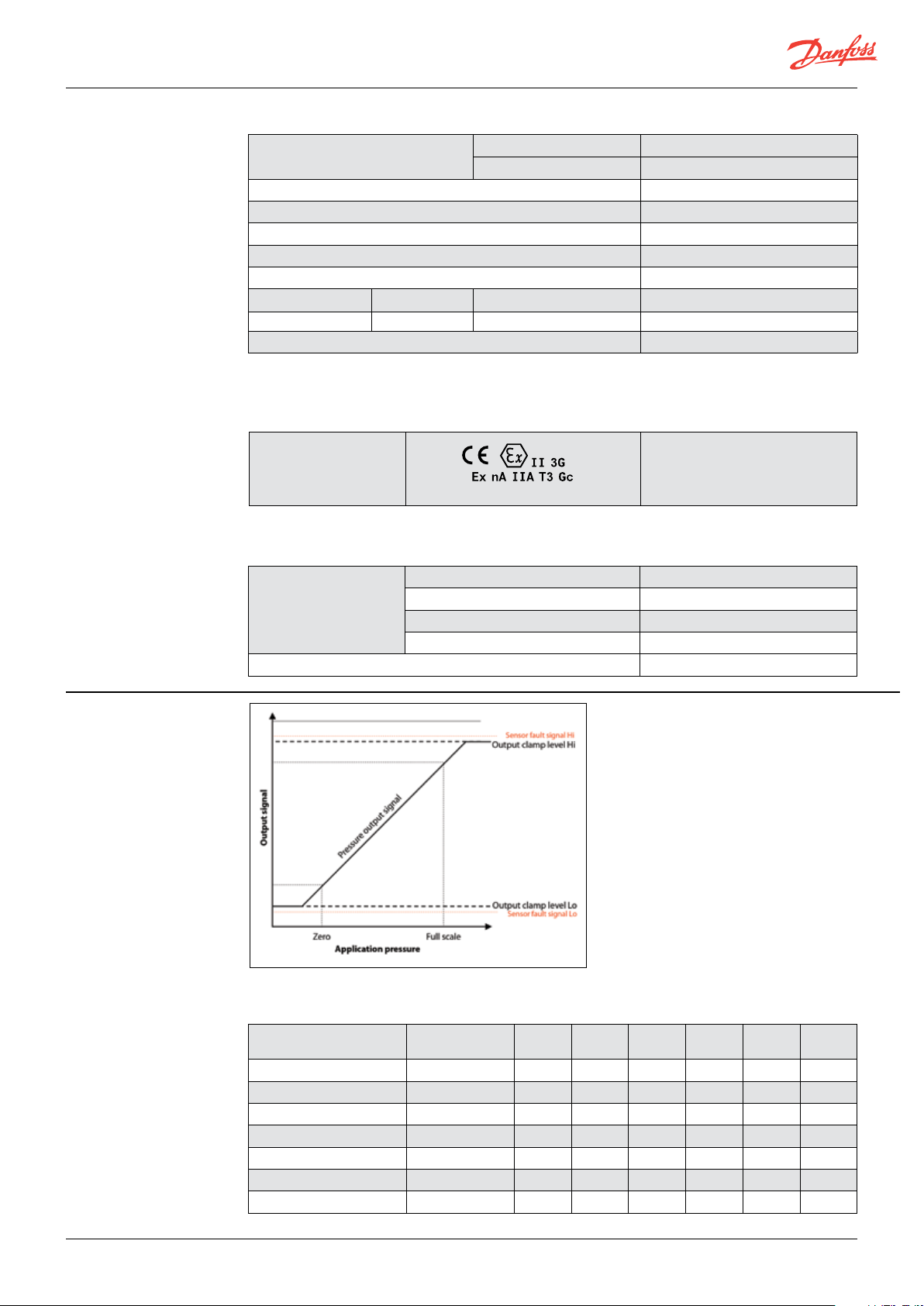
Output and diagnostics
Pressure output signal
- Defines the measuring range of the sensor.
Output clamp levels
- Limit the pressure output signal if the
pressure rises above or falls below the normal
range.
Sensor fault signal
- Output at this level signals a sensor fault.
The fault signal setting can be high or low.
Flexible output clamping and flexible fault
signal error level to application fit available.
Contact Danfoss for detailed information and
requirements.
Self-diagnostic default levels
* programmable filtering available
Ratiometric % of
supply voltage
Zero 10% 4mA 0V 1V 1V 0V 1V
FS 90% 20mA 5V 5V 6V 10V 10V
Span 80% 16mA 5V 4V 5V 10V 9V
Output clamp level Lo 4% 3,8mA NA 0,5V 0,5V N/A 0,5V
Output clamp level Hi 99% 20,5mA 5,5V 5,5V 6,5V 11V 11V
Fault signal Lo 2% - - - - - -
Fault signal Hi - 21,5mA 5,8V 5,8V 6,8V 11,5V 11,5V
4-20mA 0-5V 1-5V 1-6V 0-10V 1-10V
© Danfoss | DCS (im) | 2021.01
AI366219695189en-000202 | 3
Page 4

Data sheet | Pressure transmitter for industrial applications, DST P300
Ordering standard
DST P300
Standard 0 0
With pulse-snubber 5 0
Measuring range
0 – 1 bar
0 – 1.6 bar
0 – 2.5 bar
0 – 4 bar
0 – 6 bar
0 – 10 bar
0 – 16 bar
0 – 25 bar
0 – 40 bar
0 – 60 bar
0 – 100 bar
0 – 160 bar
0 – 250 bar
0 – 400 bar
0 – 600 bar
– – –
10 FA09
12 FA12
14
16
18
20
22
24
26
28 A1
30 A6
32 A3
34 E3
36 A8
38 C8
Gasket / O-ring material
0
No gasket
2
Gasket, NBR -40 – 85 °C
4
O-ring, NBR -40 – 85 °C
Pressure connection
AB04
G ¼ A (EN 837) (MBS 3000 only)
AB06
G ⁄ A (EN 837) (MBS 3000 only)
AB08
G ½ A (EN 837)
AC04
¼ – 18 NPT
AC08
½ – 14 NPT (MBS 3000 only)
GB04
DIN 3852-E-G ¼,
DIN 3852-E-M14 x 1.5
DIN 3852/3, M18 x 1.5-6g
9
FD10
/16 – 18 UBF - 2A (SAEJ514)
Electrical connection
Figures refer to plug
and standard PIN configuration – see page 6 & 7
Plug Pg 9 (EN 175301-803-A)
Plug, Pg 11 (EN 175301-803-A)
Screened cable, 2 m
* Plug, EN 60947-5-2, M12 × 1; 4-pin; male, excl. female plug
* Plug, AMP Superseal 1.5 series male, excl. female plug
Bayonet plug, ISO 15170-A1-3.2 Sn (Ratiometric output only)
* Plug, AMP 173065, male flying leads 125 mm excl. female plug
D9
G1
* Plug, AMP Econoseal, J series, male excl. female plug
Non-standard build-up
combinations may be
selected.
However, minimum order
quantities may apply.
Please contact your
local Danfoss office
for further information.
Gauge (relative)
Absolute
Preferred versions
1 1
4 – 20 mA
2 2
0 – 5 V
3
1 – 5 V
4
1 – 6 V
5
0 – 10 V
7
1 – 10 V
6
Ratiometric, 10 – 90%
Output signalPressure reference
* Gauge versions only available
as sealed gauge versions
4 | AI366219695189en-000202
© Danfoss | DCS (im) | 2021.01
Page 5

Data sheet | Pressure transmitter for industrial applications, DST P300
38
39.5
3
4
39.5
Dimensions/Combinations
AMP Econoseal
Flying leads
AMP 173065, male,
3.2-SN
ISO 15170-A1-
Pg 11
(SAE J514)
– 18 UNF-2A
16
/
9
DIN 3852/3,
M 18 × 1.5 – 6 g
x 1.5
DIN 3852-E-M14
R
DIN 3852-E-G ¼
30 – 35 Nm 30 – 35 Nm 30 – 35 Nm 30 – 35 Nm
A1 A3 E3 A8 A6 C8 D9 G1
Type
code
EN 175301-803-A
AMP Superseal
EN 60947-5-2
M12 × 1; 4-pin
cable
2 m screened
Pg 9
EN175301-803-A,
¼ – 18 NPT ½ – 14 NPT
G ½ A
(EN 837)
A
(EN 837)
G 3/8
G ¼ A
(EN 837)
Type code AB04 AB06 AB08 AC04 AC08 GB04 FA09 FA12 FD10
tightened
2 – 3 turns
after finger
tightened
2 – 3 turns
after finger
30 – 35 Nm 30 – 35 Nm 30 – 35 Nm
)
1
torque
Recommended
) Depends on different parameters such as gasket material, mating material, thread lubrication and pressure level
1
© Danfoss | DCS (im) | 2021.01
AI366219695189en-000202 | 5
Page 6

Data sheet | Pressure transmitter for industrial applications, DST P300
Electrical connections
Type code A1 & A6 A3 E3 A8
EN 175301-803-A,
Pg 9 & Pg 11 2 m screened cable
EN 60947-5-2
M12 × 1; 4-pin
AMP Superseal
1.5 series (male)
Ambient temperature -40 – 85 °C -30 – 85 °C -25 – 90 °C - 30 – 85 °C
Enclosure
(IP protection fulfilled toge-
IP65 IP67 IP67 IP67
ther with mating connector)
Material
Electrical connection,
4 – 20 mA output
(2 wire)
Glass filled
polyamid, PA 6.6
Pin1: + supply
Pin 2: ÷ supply
Pin 3: not used
1
)
Poliolyfin cable with
PE shrinkage tubing
Brown wire: + supply
Black wire: ÷ supply
Red wire: not used
Orange: not used
Screen: not connected
to MBS enclosure
Nickel plated
brass, CuZn/Ni
Pin 1: + supply
Pin 2: not used
Pin 3: not used
Pin 4: ÷ supply
Glass filled
polyamid, PA 6.6 2)
Pin 1: + supply
Pin 2: ÷ supply
Pin 3: not used
Earth: Connected
to MBS enclosure
Electrical connection,
0 – 5 V, 1 – 5 V, 1 – 6 V,
0 – 10 V, 1 – 10 V output
Pin 1: + supply
Pin 2: ÷ supply/common
Pin 3: + output
Brown wire: + output
Black wire: ÷ Supply/Common
Red wire: + supply
Orange: not used
Screen: not connected
to MBS enclosure
Pin 1: + supply
Pin 2: not used
Pin 3: + output
Pin 4: ÷ supply/common
Pin 1: + supply
Pin 2: ÷ supply/common
Pin 3: + output
Earth: Connected
to MBS enclosure
Electrical
connection
Ratiometric
output, 10-90%
of supply voltage
Pin 1: + supply
Pin 2: ÷ Supply/Common
Pin 3: output
Earth: Connected
Brown wire: output
Black wire:÷ Supply/Common
Red wire: + Supply
Orange: Not used
Screen: Not connected to MBS
enclosure
Pin 1: + supply
Pin 2: Not used
Pin 3: output
Pin 4: ÷ supply/Common
Pin 1: + supply
Pin 2: ÷ supply/Common
Pin 3: +output
to MBS enclosure
1)
Female plug: Glass filled polyester, PBT
2)
Wire: PTFE (teflon) Protection sleeve: PBT mesh (polyester)
6 | AI366219695189en-000202
© Danfoss | DCS (im) | 2021.01
Page 7

Electrical connections
(continued)
Type code C8 D9 G1
ISO 15170 -A1-3.2-Sn
Bayonet
AMP 173065, male
Flying leads 125 mm
AMP Econoseal
J series (male)
Ambient temperature -40 – 85 °C -40 – 85 °C -30 – 85 °C
Enclosure
(IP protection fulfilled together with
IP67/IP69 IP67 IP67
mating connector)
Material
Electrical connection,
4 – 20 mA output
(2 wire)
Electrical connection,
0 – 5 V, 1 – 5 V, 1 – 6 V,
0 – 10 V, 1 – 10 V output
Electrical connection
Ratiometric
output, 10-90%
of supply voltage
Glass filled
polyester PBT
2
)
-
-
Pin 1: + supply
Pin 2: ÷ supply/common
Pin 3: + output
Pin 4: Not used
Glass filled
polyester, PBT
2
)
Pin 1: + supply
Pin 2: - supply
Pin 3: not used
Pin 1: + supply
Pin 2: - supply/Common
Pin 3: + output
-
Glass filled
polyamide, PA 6.61)
Pin 1: + supply
Pin 2: ÷ supply/common
Pin 3: not used
Pin 1: + supply
Pin 2: ÷ supply/Common
Pin 3: + output
Pin 1: + supply
Pin 2: ÷ supply/common
Pin 3: + output
1)
Female plug: Glass filled polyester, PBT
2
)Wire: PTFE (teflon) Protection sleeve: PBT mesh (polyester)
7 | AI366219695189en-000202
© Danfoss | DCS (im) | 2021.01
 Loading...