

Page 1
Data Sheet
Pressure transmitter
Type DST P140
For industry applications
The Danfoss Sensor Technology (DST) P140 is
designed for use in industrial applications like
Booster Pumps and Air Compressors.
Drawn from over 30 years of experience with
MEMS technology, the DST P140 oers
outstanding performance in a compact and
durable stainless-steel package.
Running a powerful ARM-based
microcontroller, the DST P140 oers diagnostic
features and performance features at a
competitive level.
Features
• Hermetically sealed media interface (all
stainless steel, fully welded)
• Compact and cost eective design for OEM
applications
• Superior shock and vibration resistance
• High overload and burst pressure
• Robust electronics platform for harsh
electrical environments
AI318827388056en-000602
Page 2
Accuracy @ 20 °C
≤ ±0.5% FS
Total error band
0 - 100 ºC: 2%
-40 - 0 ºC: 3%
Response time
< 2 ms
Overload pressure
4 × FS
Burst pressure
5 × FS
Durability, P: 10-90% FS
>10 mil. cycles
Nom. output signal (short-circuit protected)
4 − 20 mA
Supply voltage [UB], polarity protected
8 - 28 V
Supply voltage dependency
≤ ±0.1% FS/10 V
Load [RL] (load connected to 0 V)
RL ≤ (UB-8V)/0.022 A
Media temperature range
-20 –110 °C - (0.34*ambient)
Ambient temperature range
-40 – 85 °C
Storage temperature range
−50 –150 °C
EMC - Emission
EN 61000-6-3
EMC Immunity up to 6 GHz
EN 61000-6-2
Insulation resistance
> 100 MΩ at 500 V
Vibration resistance
Random
10 grms, 5 Hz - 2 kHz
IEC 60068-2-64
Shock resistance
Shock
500 g / 1 ms
IEC 60068 - 2 - 27
Enclosure with mating connector
IP67
Wetted parts
AISI 304L
AISI 316L
Electrical connections
see Electrical connections section
Weight (depending on pressure connection and electrical connection)
< 100 g
Pressure transmitter, type DST P140
Product specication
Technical data
Table 1: Performance
Table 2: Electricl specications
Table 3: Environmental conditions
Table 4: Mechanical characteristics
© Danfoss | Climate Solutions | 2021.04 AI318827388056en-000602 | 2
Page 3
Application pressure
Zero Full scale
Output signal [mA]
4,0
20,0
Fault detection signal
Output clamping
Output clamping
20,5
3,8
21,5
Pressure transfer function
Pressure transmitter, type DST P140
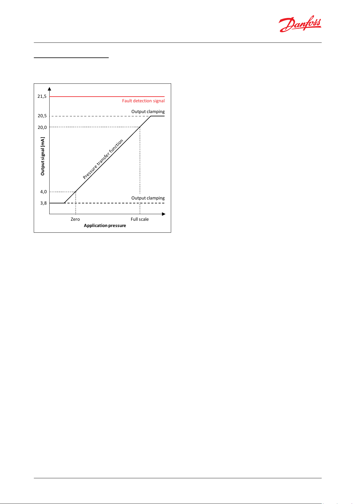
Output and diagnostics
4 - 20 mA example
Figure 1: Output and Diagnostics
Output clamping levels
• Limit the output signal if the pressure rises above or falls below the normal range
Fault detection signal level
• Placed above the pressure output range. Output at this level signals a sensor fault
Contact Danfoss for detailed information and requirements.
© Danfoss | Climate Solutions | 2021.04 AI318827388056en-000602 | 3
Page 4

M12x1.0
Metri-Pack 150.2 (Round)
G ¼A - ISO 1179-2
¼-18NPT
Metri-Pack 150.2 (Round)
M12
G1/4
44,1
58,1
46,45
31,45
R 1/4
G ¼A - ISO 1179-2
R ¼ - ISO 7-1
M12x1.0
Metri-Pack 150.2 (Round)
HEX 27
Pin A
Pin B
Pin C
Ø29.5
Pin-plating
Gold (Au)
Tin (Sn)
Pin conguration
Pin 1: +Supply
Pin 2: not connected
Pin 3: -Supply
Pin A: -Supply
Pin B: +Supply
Pin C: not connected
Pressure transmitter, type DST P140
Dimensions / Combinations
Table 5: Dimensions
Table 6: Dimensions
Electrical connections
Table 7: Electrical connection specications
© Danfoss | Climate Solutions | 2021.04 AI318827388056en-000602 | 4
Page 5

Type
Pressure refer‐
ence
Pressure ranges
Electrical connec‐
tion
Output signal
Pressure connec‐
tion
Standard
Code no.
(1)
DST P140
Gauge
0 -4 bar
M12x1.0
4 - 20 mA
G ¼A
ISO 1179-2
075G4034
0 - 6 bar
075G4035
0 - 10 bar
075G4027
0 - 16 bar
075G4029
0 - 25 bar
075G4031
0 - 40 bar
075G4033
0 - 4 bar
Metri-Pack 150
(Round)
G ¼A
ISO 1179-2
075G4064
0 - 6 bar
075G4052
0 - 10 bar
075G4053
0 - 16 bar
075G4054
0 - 25 bar
075G4055
0 - 40 bar
075G4056
0 - 100 psi
Metri-Pack 150
(Round)
¼-18NPT
8 mm Ø
ANSI/ASME B1.20.1
075G4026
0 - 150 psi
075G4028
0 - 200 psi
075G4030
0 - 300 psi
075G4032
0 - 4 bar
M12x1.0
R ¼
None
075G4073
0 - 6 bar
075G4074
0 - 10 bar
075G4059
0 - 16 bar
075G4060
0 - 25 bar
075G4061
0 - 40 bar
075G4075
Type
I-Pack Code no.
Qty/Box
Description
Cable with Metri-Pack 150 (Round) mating connector
060G8085
60 pcs
0.8 m with outer sheath
Cable with Metri-Pack 150 (Round) mating connector
060G8086
60 pcs
1.3 m with outer sheath
Cable with Metri-Pack 150 (Round) mating connector
060G8193
100 pcs
1.7 m with outer sheath
Cable with Metri-Pack 150 (Round) mating connector
064G0910
(1)
14 pcs
10 m with outer sheath
Cable with Metri-Pack 150 (Round) mating connector
060G8195
100 pcs
1 m without outer sheath
Cable with Metri-Pack 150 (Round) mating connector
060G8196
100 pcs
2.5 m without outer sheath
Cable with M12 mating connector
060G8198
60pcs
2m shielded
M12 to PG9 angle adaptor
060G8227
60pcs
-
M12 to PG9 straight adaptor
060G8228
60pcs
-
Pressure transmitter, type DST P140
Ordering
Table 8: Ordering type
(1)
(1)
Are delivered in I-pack of 60 pcs., and must therefore be ordered in multiplum of 60 pcs.
Are delivered in I-pack of 60 pcs., and must therefore be ordered in multiplum of 60 pcs.
Accessories
Table 9: Cable accessories
(1)
(1)
Multi Pack code number is 064G0950
Multi Pack code number is 064G0950
For more options and info, please go to https://store.danfoss.com
© Danfoss | Climate Solutions | 2021.04 AI318827388056en-000602 | 5
Page 6

File name
Document type
Document topic
Approval authority
060R3142.06
Manufacturers Declaration
PED
Danfoss
E494625
Electrical - Safety Certicate
-ULE510763
Electrical - Safety Certicate
-
UL
Pressure transmitter, type DST P140
Certicates, declarations, and approvals
The list contains all certicates, declarations, and approvals for this product type. Individual code number may have
some or all of these approvals, and certain local approvals may not appear on the list.
Some approvals may change over time. You can check the most current status at danfoss.com or contact your local
Danfoss representative if you have any questions.
Table 10: Certicates and declarations
Conformity
• CE marked
• RoHS compliant
• EAC declaration
• UL (le no: E494625)
• NSF and WRAS listed for ¼-18NPT and R1/4 versions
© Danfoss | Climate Solutions | 2021.04 AI318827388056en-000602 | 6
Page 7

Online support
Danfoss oers a wide range of support along with our products, including digital product information, software,
mobile apps, and expert guidance. See the possibilities below.
The Danfoss Product Store
The Danfoss Product Store is your one-stop shop for everything product related—no matter where
you are in the world or what area of the cooling industry you work in. Get quick access to essential
information like product specs, code numbers, technical documentation, certications, accessories,
and more.
Start browsing at store.danfoss.com.
Find technical documentation
Find the technical documentation you need to get your project up and running. Get direct access to
our ocial collection of data sheets, certicates and declarations, manuals and guides, 3D models
and drawings, case stories, brochures, and much more.
Start searching now at www.danfoss.com/en/service-and-support/documentation.
Danfoss Learning
Danfoss Learning is a free online learning platform. It features courses and materials specically
designed to help engineers, installers, service technicians, and wholesalers better understand the
products, applications, industry topics, and trends that will help you do your job better.
Create your Danfoss Learning account for free at www.danfoss.com/en/service-and-support/learning.
Get local information and support
Local Danfoss websites are the main sources for help and information about our company and
products. Find product availability, get the latest regional news, or connect with a nearby expert—all
in your own language.
Find your local Danfoss website here: www.danfoss.com/en/choose-region.
Spare Parts
Get access to the Danfoss spare parts and service kit catalog right from your smartphone. The app
contains a wide range of components for air conditioning and refrigeration applications, such as
valves, strainers, pressure switches, and sensors.
Download the Spare Parts app for free at www.danfoss.com/en/service-and-support/downloads.
Danfoss can accept no responsibility for possible errors in catalogues, brochures and other printed material. Danfoss reserves the right to alter its
products without notice. This also applies to products already on order provided that such alterations can be made without subsequential
changes being necessary in specications already agreed. All trademarks in this material are property of the respective companies. Danfoss and
the Danfoss logotype are trademarks of Danfoss A/S. All rights reserved.
© Danfoss | Climate Solutions | 2021.04 AI318827388056en-000602 | 7
 Loading...