

Page 1
Data Sheet
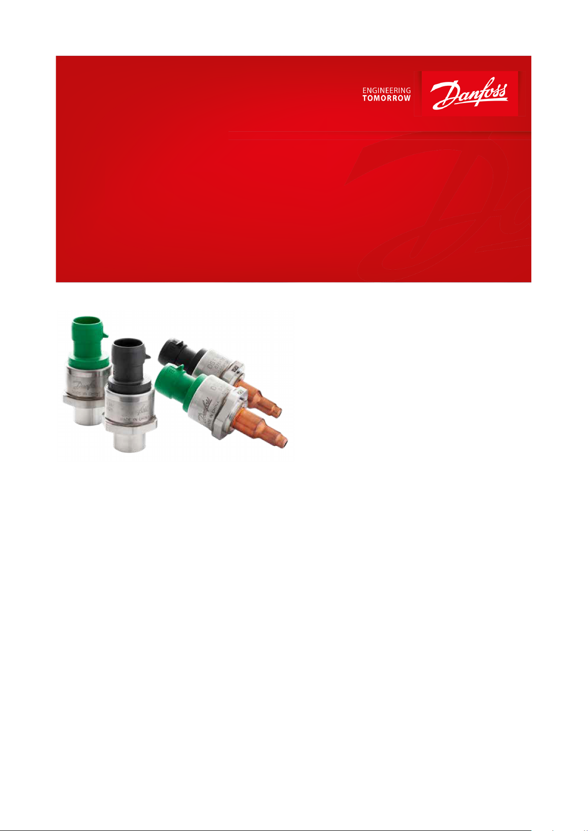
Pressure Transmitter
Type DST P110
For cooling applications
The Danfoss DST P110 series pressure
transmitter is designed for demanding
refrigeration, air conditioning and industrial
cooling applications, such as:
• Chillers
• Transport refrigeration
• Commercial refrigeration
• Variable speed HVAC
• Heat pumps
• Variable refrigerant ow (VRF)
Drawn from over 30 years of experience with
MEMS pressure sensing, the DST P110 oers
outstanding performance in a compact and
durable stainless-steel package.
Running a powerful ARM-based
microcontroller, the DST P110 oers diagnostic
features and scalable performance features at a
competitive price.
Features
• Hermetically sealed media interface (all
stainless steel, fully welded)
• Compatible with all refrigerants
• Industry leading accuracy over a broad
temperature range
• Compact and cost eective design for OEM
applications
• Self-diagnostics minimize warranty costs
• Enables harness fault detection
• Superior shock and vibration resistance
• High overload and burst pressure
• Robust electronics platform for harsh
electrical environments
• Low heat conduction Bi-metal solder tube
(Copper/Stainless Steel) version available.
AI277436397784en-001001
Page 2
Total error band
± 1% FS (within specied temperature range
(1)
)
Durability, P: 10%-110%
10 x 106 cycles
Burst pressure
300 bar
Overload pressure
4 x FS pressure
Response time
< 2 ms
Media temperature range
-40 – 135 °C
Ambient temperature range
-40 – 125 °C
(2)
Storage temperature range
-50 – 125 °C
Voltage supply
5 V ± 10%
Load [RL] (load connected to ground)
RL ≥ 2 kΩ at 5 V DC
Output modes
Ratiometric (10-90% Vss)
Output limiting (clamping)
Low clamp 4% Vss
High clamp 99% Vss
Over and reverse voltage
Protected to 16 V
Short circuit
Protected to 16 V
Miswiring
Protected
Diagnostic fault signal
2% Vss
EMC compatibility
EN 61000-6-3
EN 61000-6-2
ESD
IEC 61000-4-2 8 kV contact, 15 kV air
Insulation resistance
>100M Ohm at 500 V DC
Vibration resistance
16.5 g (20-2000 Hz)
EN 60068-2-64
Shock resistance
1000 g (half sinus, 1 ms)
EN 60068-2-27
Enclosure material
AISI 304L Stainless steel and PBT (30% glass reinforced)
Material with media contact
AISI 304L Stainless steel; AISI 316L Stainless steel
Weight
approx. 61 g for solder tube & 62 g for female are
Enclosure
IP 67
Pressure Transmitter, type DST P110
Product specication
Technical data
(1)
(1)
See code number table for focused accuracy ranges
See code number table for focused accuracy ranges
Table 1: Overload and burst pressure
Table 2: Environmental conditions
(2)
(2)
Contact Danfoss for higher temperatures
Contact Danfoss for higher temperatures
© Danfoss | Climate Solutions | 2021.02 AI277436397784en-001001 | 2
Page 3
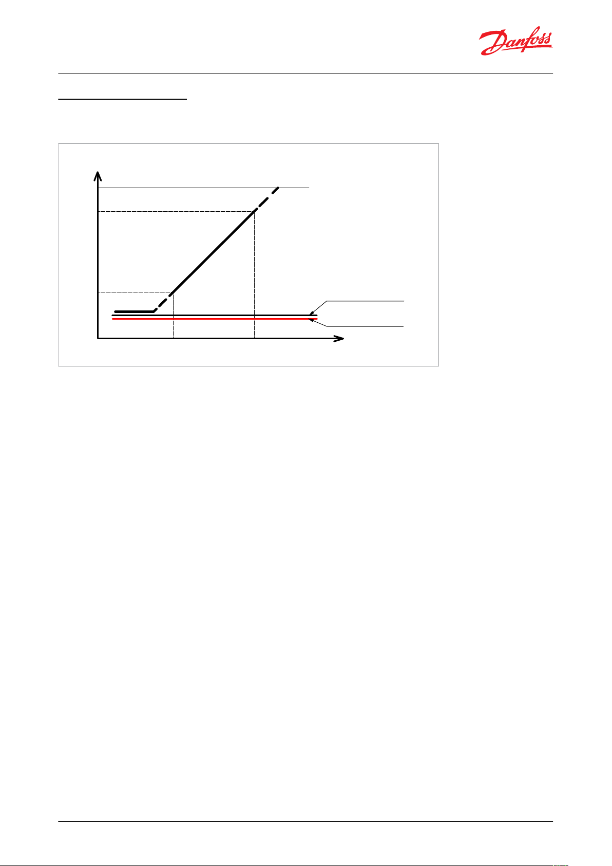
Output
[ %Vs ]
100%
90%
0%
Zero
FS
Pressure
Pressure output signal range
Clamp level 4%
10%
Fault signal 2%
Pressure Transmitter, type DST P110
Output and diagnostics
Ratiometric example
Figure 1: Output and Diagnostics
Output range
• Denes the measuring range of the sensor
Output clamp levels
• Limit the pressure output signal if the pressure rises above or falls below the normal range
Sensor fault signal
• Placed below the pressure output range. Output at this level signals a sensor fault
Harness fault detection
• Low leakage current of the sensor allows the controller to recognize harness fault conditons. (Requires a pulldown or pull-up resistor at controller interface).
If the connected controller has an internal pull up or pull down resistor at the analog channel input, then the loss of
ground or supply voltage (Vss) connection to the sensor will result in a near Vss or near ground signal voltage.
Contact Danfoss for detailed information and requirements.
© Danfoss | Climate Solutions | 2021.02 AI277436397784en-001001 | 3
Page 4

Metri-Pack 150 (Round)
Metri-Pack 150 (Round)
7/16-20 UNF
Ø17
56,1
44,1
7
4
,
8
5
4
6
,
3
5
1/4 inch
SAE female are
Solder tube
HEX 27
Pin A
Pin B
Pin C
2
7
H
E
X
Pin-plating
Tin (Sn)
Pin A: ÷Supply
Pin B: +Supply
Pin C: Output
Pressure Transmitter, type DST P110
Dimensions / Combinations
Table 3: Dimensions
Electrical connections
Table 4: Electrical connection specications
© Danfoss | Climate Solutions | 2021.02 AI277436397784en-001001 | 4
Page 5

Type
Operating range
Units
Colour code elec‐
trical connector
Focus tempera‐
ture range (1%
TEB)
Pressure port
Code no.
Code no. I-Pack
(2)
DST P110
0 – 150
psia
Green
-20 °C – 40 °C
7/16 UNF, female
(1)
075G1014
075G4003
0 – 200
psia
Green
-20 °C – 40 °C
075G1016
075G4005
0 – 400
psi sg
Black
0 °C – 80 °C
075G1019
075G4008
0 – 500
psi sg
Black
0 °C – 80 °C
075G1021
075G4010
-1 – 12
bar sg
Green
-20 °C – 40 °C
075G1013
075G4002
-1 – 34
bar sg
Black
0 °C – 80 °C
075G1018
075G4007
-1 - 49
bar sg
Black
-30 °C – 40 °C
075G1080
075G4058
0 – 10
bar sg
Green
0 °C – 80 °C
075G1012
075G4001
0 – 15
bar sg
Green
-20 °C – 40 °C
075G1085
075G4063
0 – 20
bar sg
Green
-20 °C – 40 °C
075G1015
075G4004
0 – 30
bar sg
Black
0 °C – 80 °C
075G1017
075G4006
0 – 32
bar sg
Black
0 °C – 80 °C
075G1036
075G4019
0 – 50
bar sg
Black
0 °C – 80 °C
075G1020
075G4009
0 – 10
bar
Green
-40 °C – 40 °C
Solder tube
075G1072
075G4051
0 – 30
bar
Black
0 °C – 100 °C
075G1071
075G4050
Electrical connection
Round Packard , Metri-Pack
Type
I-Pack Code no.
Qty/Box
Description
Cable with Metri-Pack 150 (Round) mating connector
060G8085
60 pcs.
0.8 m with outer sheath
Cable with Metri-Pack 150 (Round) mating connector
060g8086
60 pcs.
1.3 m with outer sheath
Cable with Metri-Pack 150 (Round) mating connector
064G0910
(1)
14 pcs.
10 m with outer sheath
Pressure Transmitter, type DST P110
Ordering
Table 5: Standard ordering type
(1)
(1)
¼” are with a deator pin
¼” are with a deator pin
(2)
(2)
I- Pack contains 60 pcs. per box for 7/16 UNF & 55 pcs. per box for solder tube
I- Pack contains 60 pcs. per box for 7/16 UNF & 55 pcs. per box for solder tube
Electrical connector colour coding:
• Black: High pressure prole
• Green: Low pressure prole
CO2 application: Sensors with an overload pressure exceeding 90bar can be used for CO2 applications - see
overload pressure specication on Table 1: Overload and burst pressure
Accessories
Table 6: Cable accessories
(1)
(1)
Multi Pack code number is 064G0950
Multi Pack code number is 064G0950
For more options and info, please go to https://store.danfoss.com/
© Danfoss | Climate Solutions | 2021.02 AI277436397784en-001001 | 5
Page 6

File name
Document type
Document topic
Approval authority
060R3142.06
Manufacturers Declaration
PED
Danfoss
075R0015.00
Manufacturers Declaration
R32 & R290 ignition statement
Danfoss
E494625
Electrical - Safety Certicate
-ULE510763
Electrical - Safety Certicate
-
UL
Pressure Transmitter, type DST P110
Certicates, declarations, and approvals
The list contains all certicates, declarations, and approvals for this product type. Individual code number may have
some or all of these approvals, and certain local approvals may not appear on the list.
Some approvals may change over time. You can check the most current status at danfoss.com or contact your local
Danfoss representative if you have any questions.
Table 7: Certicates and declarations
Conformity
• CE marked
• RoHS compliant
• UL le for refrigeration: E31024
• UL le for Hazloc: E510763
© Danfoss | Climate Solutions | 2021.02 AI277436397784en-001001 | 6
Page 7

Online support
Danfoss oers a wide range of support along with our products, including digital product information, software,
mobile apps, and expert guidance. See the possibilities below.
The Danfoss Product Store
The Danfoss Product Store is your one-stop shop for everything product related—no matter where
you are in the world or what area of the cooling industry you work in. Get quick access to essential
information like product specs, code numbers, technical documentation, certications, accessories,
and more.
Start browsing at store.danfoss.com.
Find technical documentation
Find the technical documentation you need to get your project up and running. Get direct access to
our ocial collection of data sheets, certicates and declarations, manuals and guides, 3D models
and drawings, case stories, brochures, and much more.
Start searching now at www.danfoss.com/en/service-and-support/documentation.
Danfoss Learning
Danfoss Learning is a free online learning platform. It features courses and materials specically
designed to help engineers, installers, service technicians, and wholesalers better understand the
products, applications, industry topics, and trends that will help you do your job better.
Create your Danfoss Learning account for free at www.danfoss.com/en/service-and-support/learning.
Get local information and support
Local Danfoss websites are the main sources for help and information about our company and
products. Find product availability, get the latest regional news, or connect with a nearby expert—all
in your own language.
Find your local Danfoss website here: www.danfoss.com/en/choose-region.
Spare Parts
Get access to the Danfoss spare parts and service kit catalog right from your smartphone. The app
contains a wide range of components for air conditioning and refrigeration applications, such as
valves, strainers, pressure switches, and sensors.
Download the Spare Parts app for free at www.danfoss.com/en/service-and-support/downloads.
Danfoss can accept no responsibility for possible errors in catalogues, brochures and other printed material. Danfoss reserves the right to alter its
products without notice. This also applies to products already on order provided that such alterations can be made without subsequential
changes being necessary in specications already agreed. All trademarks in this material are property of the respective companies. Danfoss and
the Danfoss logotype are trademarks of Danfoss A/S. All rights reserved.
© Danfoss | Climate Solutions | 2021.02 AI277436397784en-001001 | 7
 Loading...