

Page 1

Operating guide
Data sheet
APP pumps
Top level inclination sensor
CANopen output
APP 0.6-1.0 / APP 1.5-3.5 / APP (W) 5.1-10.2 /
DST X730
APP 11-13 / APP 16-22 / APP 21-43
ia.danfoss.com.
ro-solutions.com
Page 2

Operation guide | DST 730 Top level inclination sensor
Table of Contents
1. General Information ........................................................................2
1.1 Contact .................................................................................2
1.2 General.................................................................................2
1.3 Abbreviations and terms ................................................................3
2. Electrical connections.......................................................................4
2.1 M12 x 1, 5-pin 43-01090 .................................................................4
2.2 6 wires output 18 AWG 1.65 mm OD .....................................................5
3. Network Management (NMT)............................................................6
8. Restore default parameter ...............................................................6
4. Baud rate ...................................................................................7
5. Node-ID and resolution .....................................................................7
6. Parameter settings..........................................................................7
7. Restore default parameters .................................................................7
8. Heartbeat ...................................................................................7
9 Error handling ..........................................................................8
10. SDO communication and read/write commands .........................................9
11. PDO communication and Angle calculation .................................................9
1. General Information
12. CANopen features summary ............................................................17
13. Status LED .................................................................................21
14. Digital filter setting ........................................................................22
15. Communication examples .................................................................22
1.1 Contac t
Danfoss A/S
Industrial Automation
DK-6430 Nordborg
Denmark
www.ia.danfoss.com
E-mail: IA-Sensorglobaltechnicalsupport@danfoss.com
1.2 General
The document describes the standard CANopen
implementations created. It is addressed to
CANopen system integrators and to CANopen
device designers who already know the
content of standards designed by C.i.A. (CAN in
Automation).
2 | © Danfoss | DCS (im) | 2019.04
AQ304230922416en-000101 | IC.PS.P21.L1.02
Page 3

Operation guide | DST X730 Top level inclination sensor
1.3 Abbreviations and terms
Abbreviation/term Definition
CAN Controller Area Network
CAL CAN Application Layer
CMS CAN Message Specification
COB Communication Object
COB-ID COB Identifier
D1 - D8 Data from 1 to 8
DLC Data Length Code
ISO International Standard Organization
NMT Network Management
PDO Process Data Object
RXSDO Receive SDO
SDO Service Data Object
TXPDO Transmit PDO
TXSDO Transmit SDO
Describes a serial communication bys that implements the “physical” level 1 and the
“data link” level 2 of the ISO/OSI reference model.
Describes implementation of the CAN in level 7 “application” of the ISO/OSI reference
model form which CANopen derives.
CAL service element. Defines the CAN Apllication Layer for the various industrial
applications.
Unit of transport of data in a CAN network (aCAN message). A maximum of 2,048 COBs
may be present i a CAN network, each of which may transport from 0 to a maximum of
8 bytes.
Identifying element of a CAN message. The identifier determines the priority of a COB
in case of multiple messages in the network.
Number of data bytes in the data field of a CAN message.
Number of data bytes transmitted in a single frame.
International authority providing standards for various merchandise sectors.
CAL service element. Describes how to configure, initialize, manage errors in a CAN
network.
Process data communication objects (with high priority).
SDO objects received from the remote device.
Service data communication objects (with low priority). The value of this data is
contained in the “Objects Dictionary” of each device in the CAN network.
PDO objects transmitted by the remote device.
SDO objects transmitted by the remote device.
© Danfoss | DCS (im) | 2019.04
NOTE:
The numbers followed by the suffix “h”
represent a hexadecimal value, with suffix “b” a
binary value, and with suffix “d” a decimal value.
The value is decimal unless specified otherwise.
AQ304230922416en-000101 | IC.PS.P21.L1.02 | 3
Page 4
Operation guide | DST 730 Top level inclination sensor
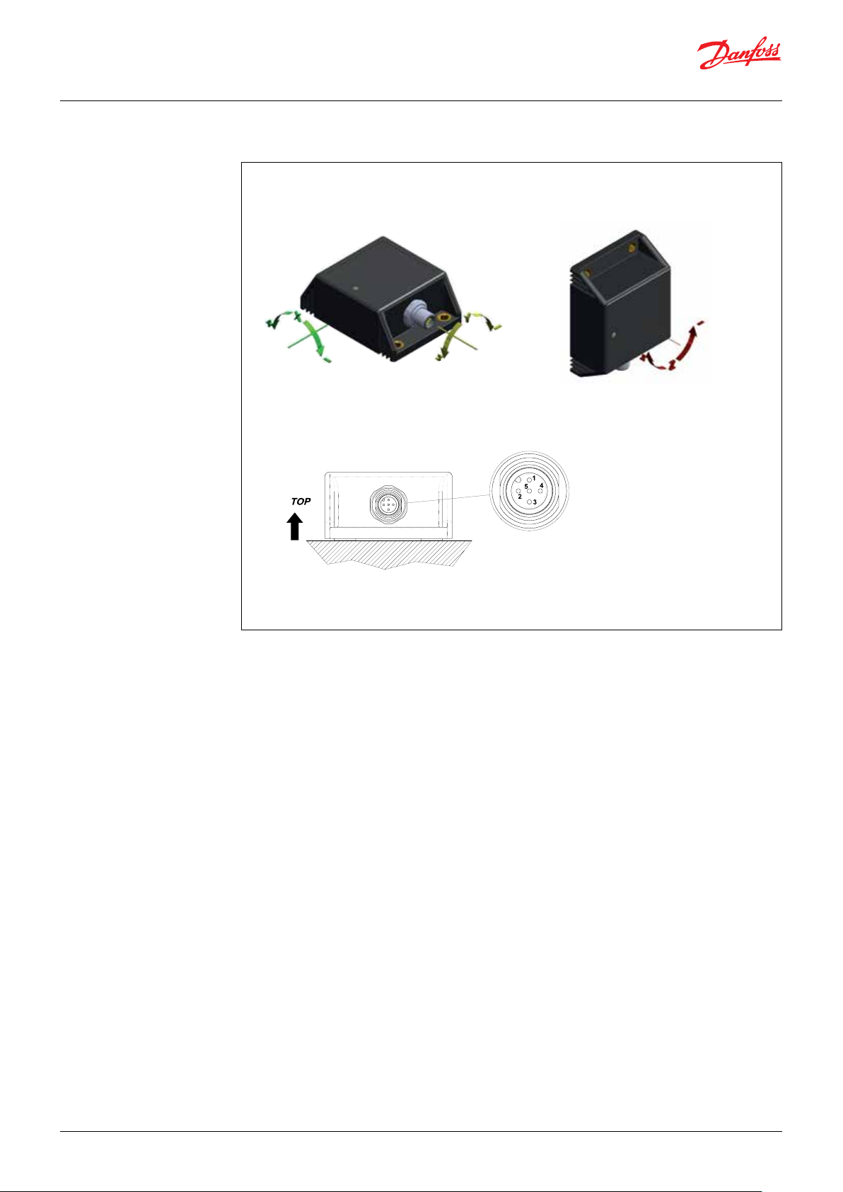
2. Electrical connections
2.1 M12 x 1, 5-pin 43-01090
CONNECTIONS
1.: NC
2.: + VS (+10 - +36 VDC)
3.: GROUND
4.: CAN-L
5.: CAN-H
NOTE:
Please make sure that the CANbus is terminated.
The impedance measured between CAN-H and
CAN-L must be 60 ohm that means the cable
must be connected to a 120 ohm resistor on each
ends of the bus line. Internally the tranducer is
not terminated with the resistor of 120 ohm.
Do not confuse the signal lines of the CAN bus,
otherwise communication with the transducer is
impossible.
4 | © Danfoss | DCS (im) | 2019.04
AQ304230922416en-000101 | IC.PS.P21.L1.02
Page 5
Operation guide | DST X730 Top level inclination sensor
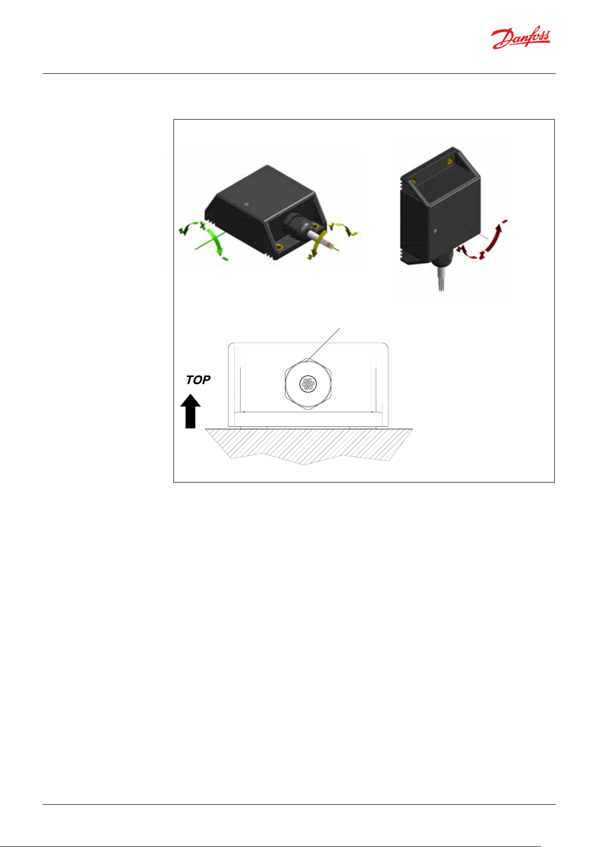
2.2 6 wires output 18 AWG 1.65 mm OD
Cables output IEC 60332
Cable 7 pole 0.5 mm²
OD 6.4 mm
NOTE:
Please make sure that the CANbus is terminated.
The impedance measured between CAN-H and
CAN-L must be 60 ohm that means the cable
must be connected to a 120 ohm resistor on each
ends of the bus line. Internally the tranducer is
not terminated with the resistor of 120 ohm.
Do not confuse the signal lines of the CAN bus,
otherwise communication with the transducer is
impossible.
CONNECTIONS
White: +Vs (+10 - +36 Vdc)
Yellow: GROUND
Grey: CAN-H
Blue: CAN-L
Pink: NC
Green: NC
Brown: NC
© Danfoss | DCS (im) | 2019.04
AQ304230922416en-000101 | IC.PS.P21.L1.02 | 5
Page 6
Operation guide | DST 730 Top level inclination sensor
3. Network Management
(NMT)
The device supports CANopen network
management functionality NMT Slave (Minimum
Boot Up).
8. Restore default
parameter
Every CANopen device contains an
international Network Management server that
communicates with an external NMT master.
One device in a network, generally the host,
may act as the NMT master.
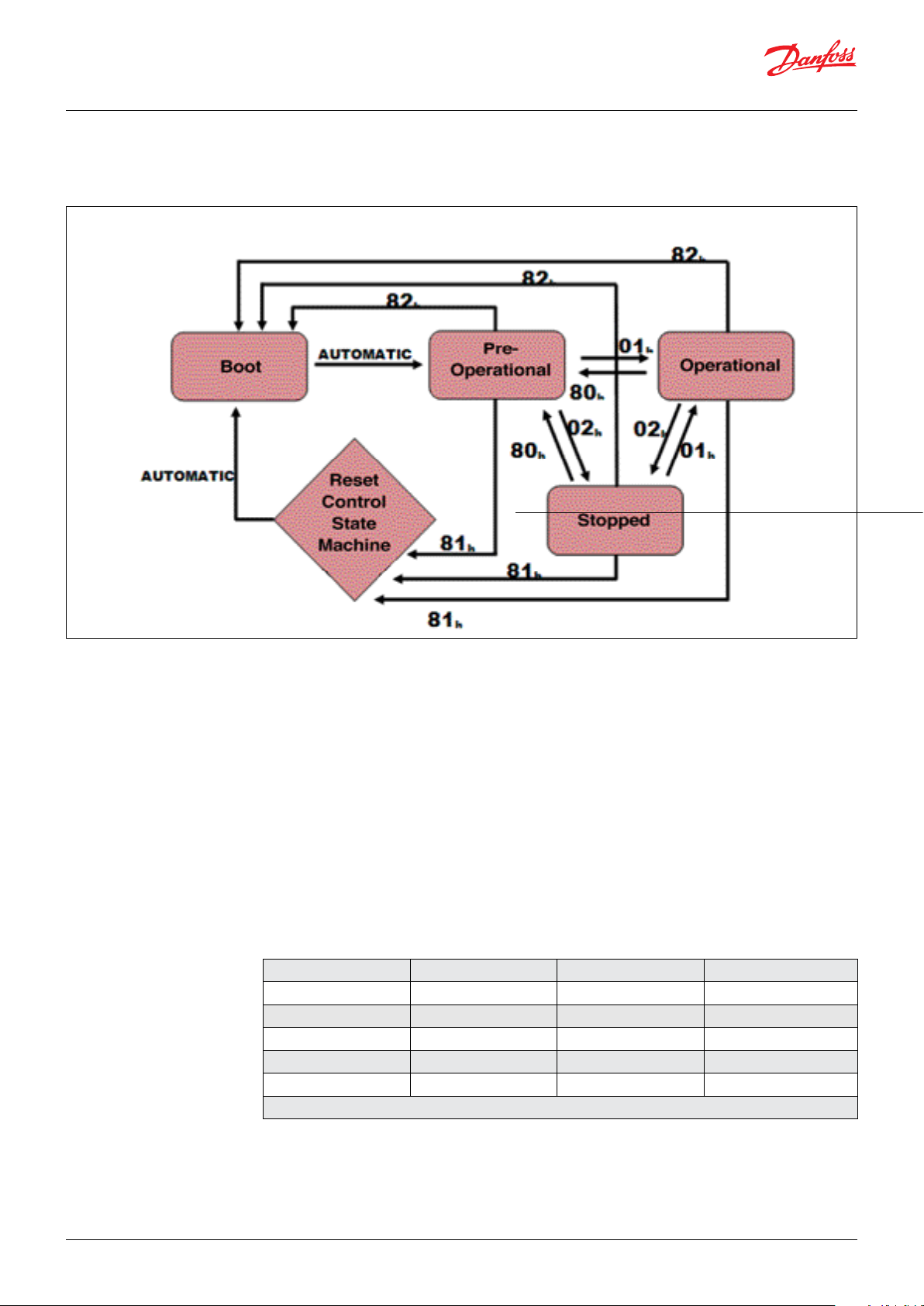
Through NMT messages, each CANopen device’s
network management server controls state
changes within its built-in Communication
State Machine.
This is independent from each node’s
operational state machine, which is device
dependant and described in Control State
Machine.
NMT Message COB-ID Data Byte 1 Data Byte 2
Start Remote Node 0 01h Node-ID’
Stop Remote Node 0 02h Node-ID’
Pre-operational State 0 80h Node-ID’
Reset Node 0 81h Node-ID’
Reset Communication 0 82h Node-ID’
* Node-ID = Drive address (from 1 to 7Fh)
It is important to distinguish a CANopen
device’s operational state machine from its
Communication State Machine.
CANopen sensors and I/O modules, for example,
have completely different operational state
machines than servo drives. The “Communication
State Machine” in all CANopen devices, however,
is identical as specified by the DS301.
NMT messages have the highest priority. The 5
NMT messages that control the Communication
State Machine each contain 2 date bytes that
identify the node number and a command to that
node’s state machine.
Table 1 shows the 5 NMT messages surpported,
and Table 2 shows the correct message for
sending these messages.
Table 1
6 | © Danfoss | DCS (im) | 2019.04
AQ304230922416en-000101 | IC.PS.P21.L1.02
Page 7

Operation guide | DST X730 Top level inclination sensor
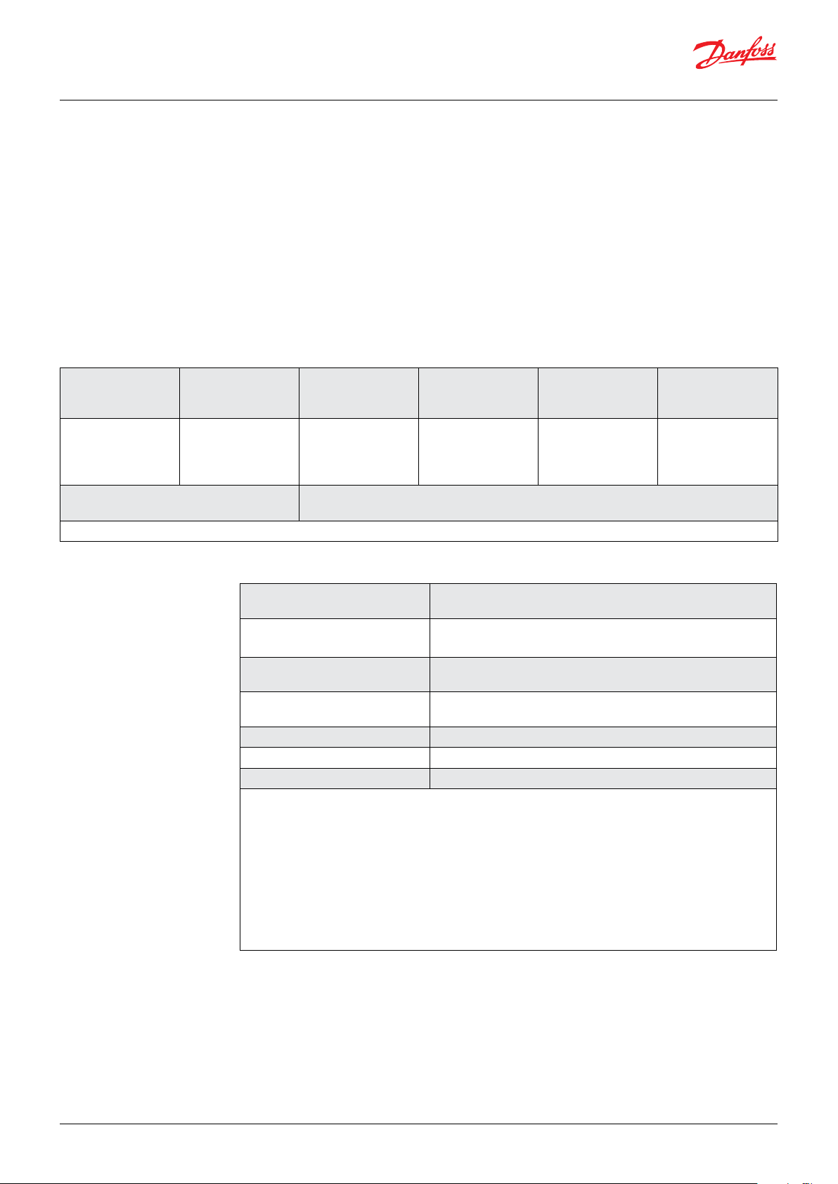
Arbitration
Field
COB-ID RTR Byte 1 Byte 2 Byte 3 Byte 4 Byte 5 Byte 6 Byte 7 Byte 8
000h 0 See table 1 See table 2 These bytes are not sent
4. Baud rate Node-ID can be configurable via SDO
communication object =x20F2 and 020F3 (see
communication examples at the end of this
coument).
The default Baud rate is 250kbit/s.
5. Node-ID and resolution Node-ID can be configurable via SDO
communication object 0x20F0 and 0x20F1 (see
communication examples at the end of this
documentation).
The default Node-ID is 7F.
6. Parameter settings All object dictionary parameters (object with
marking PARA) can be saved in a special
section of the internal EEPROM and secured by
checksum calculation.
The special LSS parameters (objects with
marking LL-PARA), also part of the objec
dictionary, will be also saved in a special
section of the internal EEPROM and secured by
checksum calculation.
Data Field
Table 2
Important Note:
Changing this parameter can disturb the network!
Use the service only if one device is connected to the
network!
Important note:
Changing this parameter can disturb the network!
Use the service only if one device is connected to the
network!
Due to the internal architecture of the
microcontroller the parameter write cycles are
limited to 100,000 cycles.
7. Restore default
parameters
8. Heartbeat
All object dictionary parameters (objects with
marking PARA) can be restored to factory default
values via SDO communication (index 0x1011).
The heartbeat mechanism for this device
isestablished through cyclic transmission of
the heartbeat message done by the heartbeat
producer.
One or more devices in the network are aware
of this heartbeat message. If the herartbeat
cycle fails from the heartbeat producer the local
application on the heartbeat consumer will be
informed about that event.
Heartbeat Message
COB-ID Byte 0
700+Node-ID Content NMT State
The implementation of either guarding or
heartbeat is mandatory.
The device supports Heartbeat Producer
functionality.
The producer heartbeat time is defined in object
0x1017.
© Danfoss | DCS (im) | 2019.04
AQ304230922416en-000101 | IC.PS.P21.L1.02 | 7
Page 8
Operation guide | DST 730 Top level inclination sensor
9 Error handling
Principle
Emergency messages (EMCY) shall be triggered
by internal errors on device and they are
assigned the highest possible priority to ensure
that they get access to the bus without delay
(EMCY Producer). By default, the EMCY contains
the error field with pre-defined error numbers
EMCY Message
The EMCY COB-ID is defined in object 0x1014.
The EMCY message consists of 8 bytes. It contains
an emergency error code, the contents of object
0x1001 and 5 byte of manufacturer specific
error code. The device uses only the 1st byte as
manufacturer specific error code.
and additional information.
Error Behavior (object 0x4000)
If a serious device failure is detected the object
0x4000 specifies, to which state the module shall
be set:
0: Pre-operational
1: Mo state change (default)
2: Stopped
Byte Byte 1
Byte 3 Byte 4 Byte 5 Byte 6
Byte 2
Description Emergency
Error code
1)
Error code 0x0000 Error Reset on no ERrror (Error Register = 0)
1)
Error Register
(object 0x1001
Manufacturer
2)
)
specific error code
(always 0x00)
Manufacturer
specific error code
(object 0x4001)
0x1000 Generic error
2)
Always 0
Byte 7
Byte 8
Manufacturer
specific error code
NOT IMPLEMENTED
(always 0x00)
Supported Manufacturer Specific Error Codes (object 0x4001)
Manufacturer Specific Error Code
(bit field)
0bxxxxxxx1
(a)
Sensor Error TYPE DST X730 Z-360 (e.g. angle under/above
Description
limits, self-test failure, MEMS IC communication error)
0bxxxxxxx1
(a)
Sensor Error X-axis TYPE DST X730 XY-0xx (e.g. angle under/
above limits, self-test failure, MEMS IC communication error)
0bxxxxxxx1
(a)
Sensor Error Y-axis TYPE DST X730 XY-0xx (e.g. angle under/
above limits, self-test failure, MEMS IC communication error)
0bxxx1xxxx Program checksum error
0bxx1xxxxx Flash limit reached - error
0bx1xxxxxx LSS Parameter checksum error
(a)
An angle error will be generated if the actual measured angle is under or above limits.
Example of limits for different versions are reported below:
DST X730 dual axis version ± 10º Error limit are ± 11º (± 11º are also the FSO angles STOP)
DST X730 dual axis version ± 15º Error limit are ± 16.5º (± 16.5º are also the FSO angles STOP)
DST X730 dual axis version ± 20º Error limit are ± 22º (± 22º are also the FSO angles STOP)
DST X730 dual axis version ± 30º Error limit are ± 33º (± 33º are also the FSO angles STOP)
DST X730 dual axis version ± 45º Error limit are ± 49.5º (± 49.5º are also the FSO angles STOP)
DST X730 dual axis version ± 60º Error limit are ± 66º (± 66º are also the FSO angles STOP)
DST X730 dual axis version ± 90º Error limit are ± 87º (± 87º are also the FSO angles STOP)
8 | © Danfoss | DCS (im) | 2019.04
AQ304230922416en-000101 | IC.PS.P21.L1.02
Page 9
Operation guide | DST X730 Top level inclination sensor
10. SDO communication and
read/write commands
COB-ID DLC Byte 1 Byte 2 Byte 3 Byte 4 Byte 5 Byte 6 Byte 7 Byte 8
600+Node-ID 8 CMD Index Sub-Index Data Data Data Data
COB-ID DLC Byte 1 Byte 2 Byte 3 Byte 4 Byte 5 Byte 6 Byte 7 Byte 8
580+Node-ID 8 RES Index Sub-Index Data Data Data Data
The device fulfils the SDO Server functionality.
With Service Data Object (S.D.O.) the access
to entries of a device Object Dictionary is
provided. As these entries may contain data of
arbitrary size and data typ SDOs can be used
to transfer multiple data sets from a client to a
server and vice versa.
Structure of SDO-request by the Master
Structure of SDO-answer by the Slave
Write Access, Data Transfer from Host to Slave
Each access to object dictionary is checked
by the slave for validity. Any write access to
nonexistent objects, to read - only objects or
with a non-corresponding data format are
rejected and answered with a corresponding
error message.
CMD determines the direction of data transfer and
the size of the data object:
23 hex Sending of 4-byte data
(bytes 5 - 8 contian a 32 bit value)
2B hex Sending of 2-byte data
(bytes 5, 6 contain a 16-bit value
2F hex Sending of 1-byte data
(byte 5 contians an 8-bit value)
Read Access, Data Transfer form Slave to Host
Any read access to non-existing objects is
answered with an error message.
CMD determines the direction of data transfer:
40 hex read access (in any case)
The Slave answers:
RES Response of the slave:
42 hex Bytes used by node when replying to
read command with 4 or less data
43 hex Bytes 5 - 8 contain a 32-bit value
4B hex Bytes 5, 6 contain a 16-bit value
4F hex Byte 5 contains an 8-bit value
80 hex Error
11. PDO communication
and Angle calculation
Byte Byte 1 Byte 2 Byte 3 Byte 4
Description
The Slave answers:
RES response of the slave:
60 hex Data sent successfully
80 hex Error
Transmit PDO #0
This PDO transmits asynchronously the position
value of the angle sensor. The Tx PDO#0 shall
be transmitted cyclically, if the cyclic timer
(object 0x1800.5) is programmed > 0. Values
between 4 ms and 65535 ms shall be selectable
by parameter settings. The Tx PDO#0 will be
transmitted by entering the “Operational” state.
Byte 5
Byte 6
Byte 7
Byte 8
X Axis
object
(0x6010)
Low-Byte
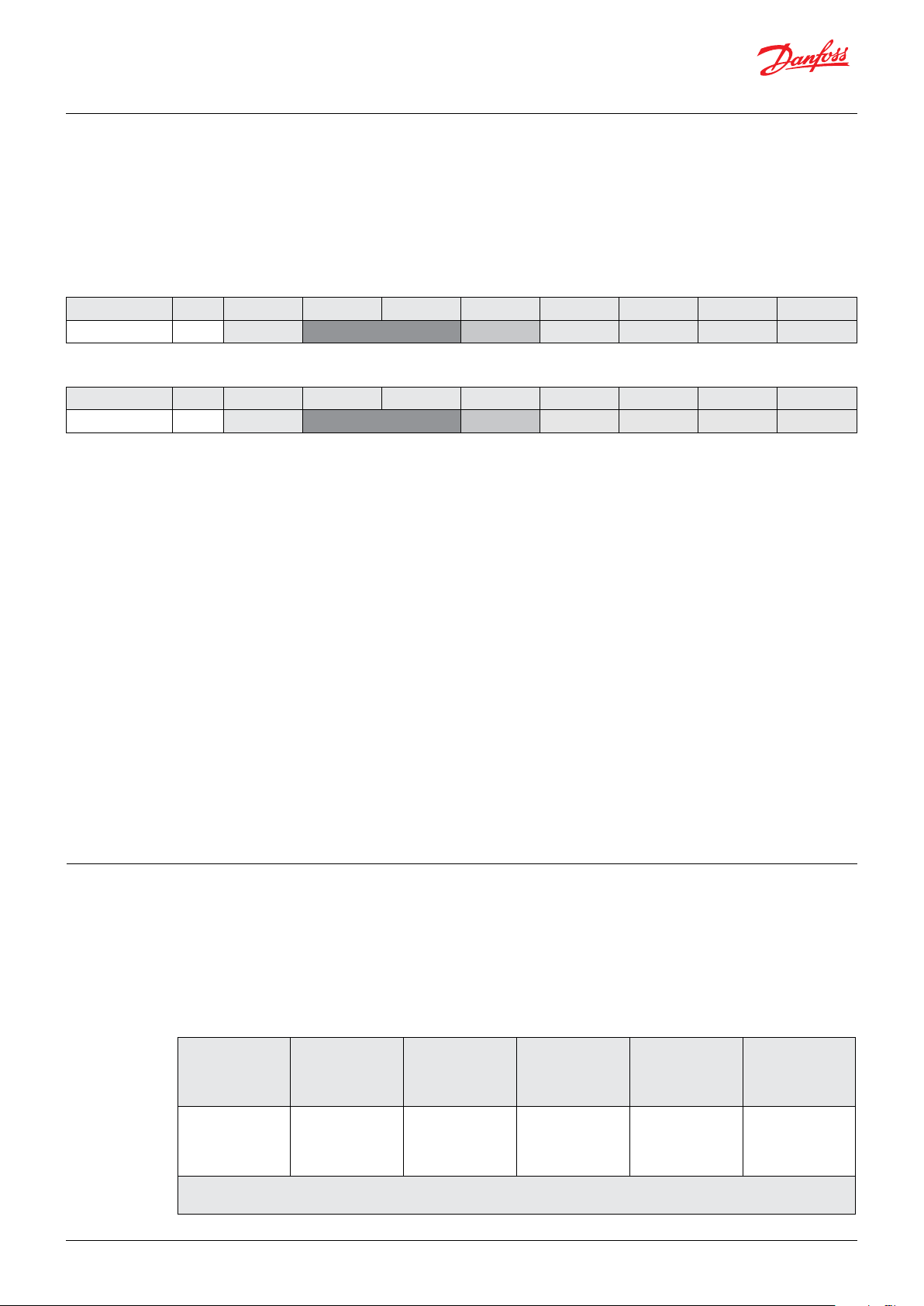
Inthe following figures an example of PDO mapping is reported in the case of Angle X = 0.00º and
Angle Y = 0.00º (Node-ID = 7Fh and resolution ± 0.01º
X Axis
object
(0x6010)
High-Byte
Y Axis
object
(0x6020)
Low-Byte
Y Axis
object
(0x6020)
High-Byte
(0x00)
© Danfoss | DCS (im) | 2019.04
AQ304230922416en-000101 | IC.PS.P21.L1.02 | 9
Page 10
Operation guide | DST 730 Top level inclination sensor
Angle X = 0.00°
Angle Y = 0.00°
ID Byte 1 Byte 2 Byte 3 Byte 4 Byte 5 Byte 6 Byte 7 Byte 8
1FFh 00h 00h 00h 00h 00h 00h 00h 00h
Angle X:
Byte 2 MSB (00h) = 00h; Byte 1 LSB (00h) = 00h;
Angle X = 0000h to decimal 0d (resolution
±0.01°) = 0.00°
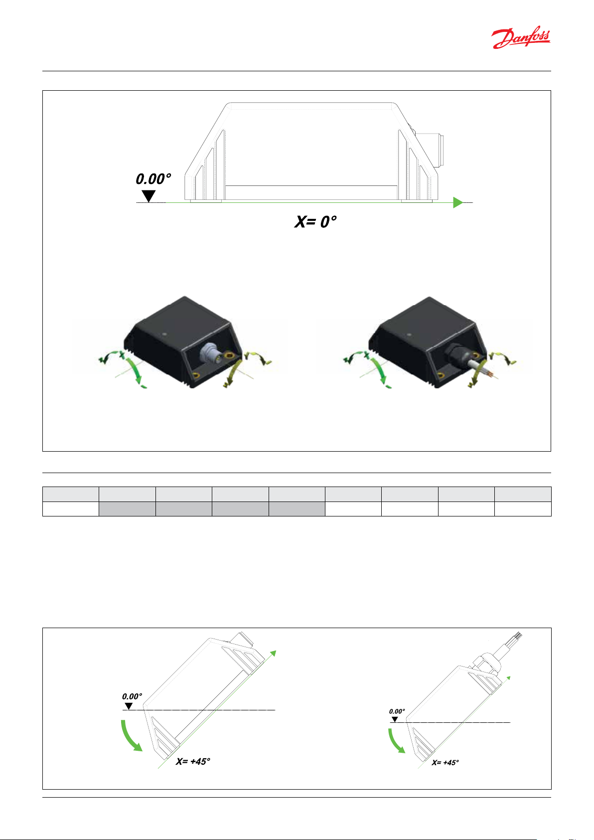
In the following figures an example of PDO
mapping is reported in the case of Angle X = +
45.00° and Angle Y = 0.00°.
(Node-ID = 7Fh and resolution ± 0.01°)
Angle X = +45.00°
Angle Y = 0.00°
Angle Y:
Byte 4 MSB (00h) = 00h; Byte 3 LSB (00h) = 00h
Angle Y = 0000h to decimal 0d (resolution
±0.01°) = 0.00°
10 | © Danfoss | DCS (im) | 2019.04
AQ304230922416en-000101 | IC.PS.P21.L1.02
Page 11
Operation guide | DST X730 Top level inclination sensor
ID Byte 1 Byte 2 Byte 3 Byte 4 Byte 5 Byte 6 Byte 7 Byte 8
1FFh 94h 11h 00h 00h 00h 00h 00h 00h
Angle X:
Byte 2 MSB (11h) = 11h; Byte 1 LSB (94h) = 94h;
Angle X = 1194h to decimal 4500d (resolution
±0.01°) = +45.00°
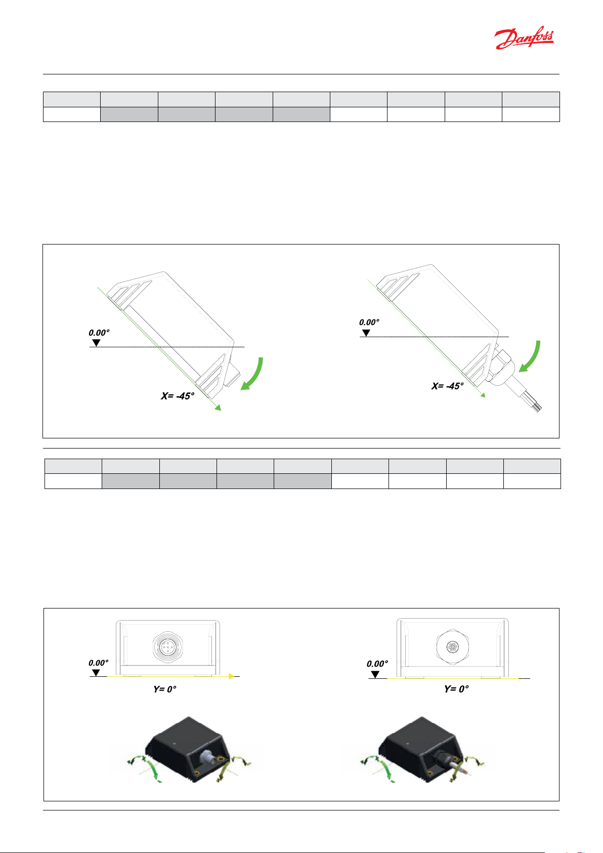
In the following figures an example of PDO mapping is reported in the case of Angle X = -45.00°
and Angle Y = 0.00°. (Node-ID = 7Fh and resolu-
tion ± 0.01º)
Angle X = -45.00°
Angle Y = 0.00°
Angle Y:
Byte 4 MSB (00h) = 00h; Byte 3 LSB (00h) = 00h
Angle Y = 0000h to decimal 0d (resolution
±0.01°) = 0.00°
ID Byte 1 Byte 2 Byte 3 Byte 4 Byte 5 Byte 6 Byte 7 Byte 8
1FFh 6Bh EEh 00h 00h 00h 00h 00h 00h
Angle X:
Byte 2 MSB (EEh) = EEh; Byte 1 LSB (6Bh) = 6Bh;
Angle X = EE6Bh to decimal 61035d
If the Angle X in decimal is greater thanm
32768, the Angle X is NEGATVE and it must be
computed as below (resolution ± 0.01°
Angle X = EE6Bh to decimal 61035d
Angle X = Angle X (in decimal) - 65535d =
61035d - 65535d = -4500d (resolution ± 0.01°)
= -45.00°
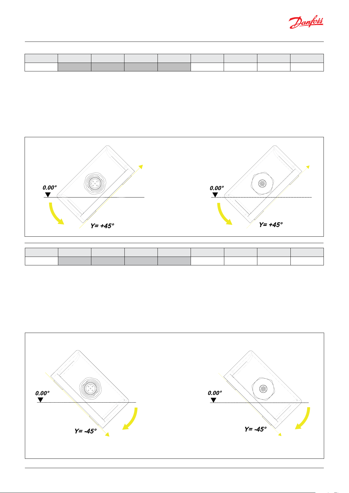
Angle X = 0.00°
Angle Y = 0.00°
Angle Y:
Byte 4 MSB (00h) = 00h; Byte 3 LSB (00h) = 00h
Angle Y = 0000h to decimal 0d (resolution ±0.01°)
= 0.00°
In the following figures an example of PDO
mapping is reported in the case of Angle X =
0.00° and Angle Y = 0.00°
(Node-ID = 7Fh and resolution ± 0.01°)
© Danfoss | DCS (im) | 2019.04
AQ304230922416en-000101 | IC.PS.P21.L1.02 | 11
Page 12
Operation guide | DST 730 Top level inclination sensor
ID Byte 1 Byte 2 Byte 3 Byte 4 Byte 5 Byte 6 Byte 7 Byte 8
1FFh 00h 00h 00h 00h 00h 00h 00h 00h
Angle X:
Byte 2 MSB (00h) = 00h; Byte 1 LSB (00h) = 00h;
Angle X = 0000h to decimal 0d (resolution
±0.01°) = 0.00°
In the following figures an example of PDO mapping is reported in the case of Angle X = 0.00°
and Angle Y = +45.00°.
(Node-ID = 7Fh and resolution ±0.01°)
Angle X = -0.00°
Angle Y = +45.00°
Angle Y:
Byte 4 MSB (00h) = 00h; Byte 3 LSB (00h) = 00h
Angle Y = 0000h to decimal 0d (resolution
±0.01°) = 0.00°
ID Byte 1 Byte 2 Byte 3 Byte 4 Byte 5 Byte 6 Byte 7 Byte 8
1FFh 00h 00h 94h 11h 00h 00h 00h 00h
Angle X:
Byte 2 MSB (00h) = 00h; Byte 1 LSB (00h) = 00h;
Angle X = 0000h to decimal 0d (resolution
±0.01°) = 0.00°
In the following figures an example of PDO mapping is reported in the case of Angle X = 0.00°
and Angle Y = +45.00°.
(Node-ID = 7FH and resolution ± 0.01°)
Angle Y:
Byte 4 MSB (11h) = 11h; Byte 3 LSB (94h) = 94h
Angle Y = 1194h to decimal 4500d (resolution
±0.01°) = +45.00°
12 | © Danfoss | DCS (im) | 2019.04
Angle X = -0.00°
Angle T = -45.00°
AQ304230922416en-000101 | IC.PS.P21.L1.02
Page 13
Operation guide | DST X730 Top level inclination sensor
ID Byte 1 Byte 2 Byte 3 Byte 4 Byte 5 Byte 6 Byte 7 Byte 8
1FFh 00h 00h 6Bh EEh 00h 00h 00h 00h
Angle X:
Byte 2 MSB (00h) = 00h; Byte 1 LSB (00h) = 00h;
Angle X = 0000h to decimal 0d (resolution
±0.01°) = 0.00°
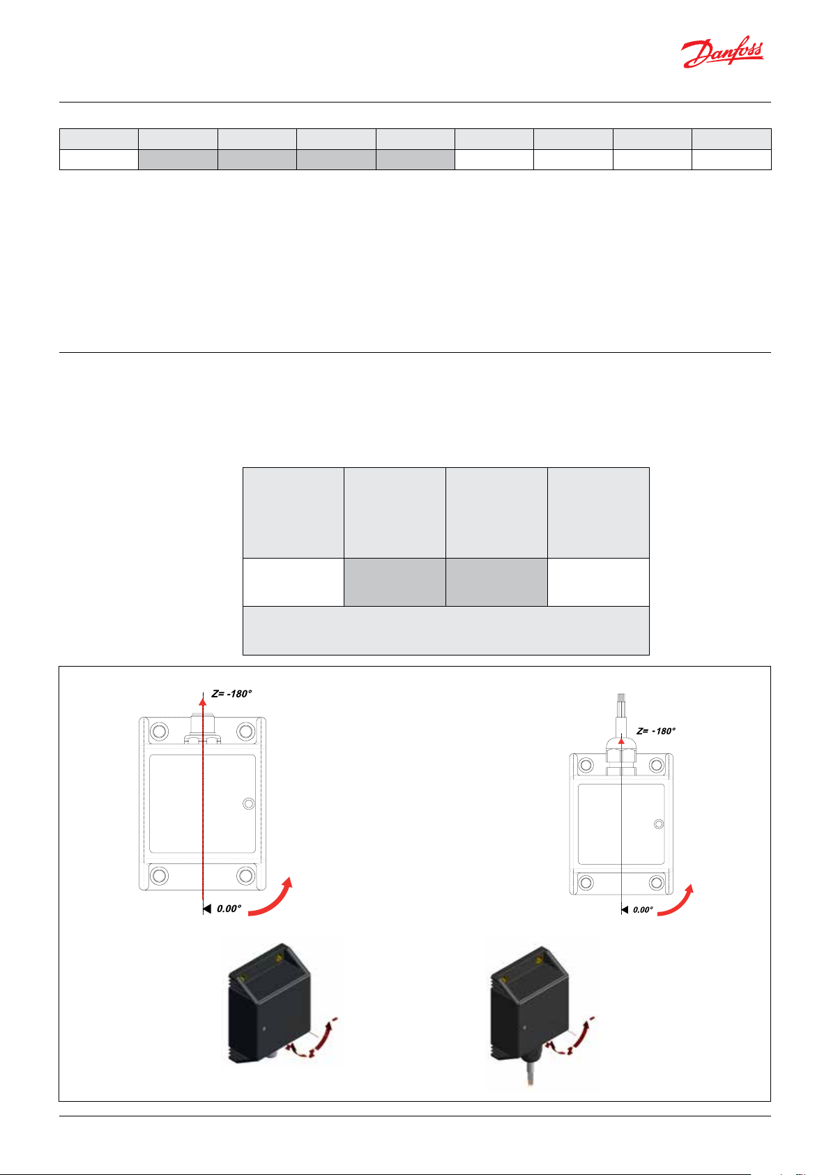
Transmit PDO#0 - Single axis configuration Z
(-180° - +180°) model DST X730 Z-360
Byte Byte 1 Byte 2
Description
Int he following figures an example of PDO mapping is reported in the case
of Angle Z = -180.0º (in 0 - 360º configuration the equivalent angle is 0.00º).
Z Axis
(object 0x6010)
Low-Byte
(Node-ID = 7Fh and resolution ± 0.01º
(object 0x6010)
Angle Y:
Byte 4 MSB (EEh) = EEh; Byte 3 LSB (6Bh) = 6Bh
Angle Y = EE6Bh to decimal 61035d
If the Angle Y in decimal is greater than 32768,
the Angle Y is NEGATIVE and it must be computed
as below (resolution ± 0.01°)
Angle Y = EE6Bh to decimal 61035d
Angle Y = Angle Y (in decimal) - 65535d = 61035d
- 65535d = -4500d (resolution ± 0.01°) = -45.00°
This PDO transmits synchronously the position
value of the inclinationsensor. The Tx PDO#0
shall be transmitted cyclically, if the cyclic timer
(object 0x1800.5) is programmed > 0. Values
between 4 ms and 65535 ms shall be selectable
by parameter settings. The Tx PDO#0 will be
transmitted by entering the “Operational” state.
Byte 3
Byte 4
Byte 5
Byte 6
Byte 7
Byte 8
Z Axis
(0x00)
High-Byte
© Danfoss | DCS (im) | 2019.04
Angle Z = -180.00°
AQ304230922416en-000101 | IC.PS.P21.L1.02 | 13
Page 14

Operation guide | DST 730 Top level inclination sensor
ID Byte 1 Byte 2 Byte 3 Byte 4 Byte 5 Byte 6 Byte 7 Byte 8
1FFh AFh B9h 00h 00h 00h 00h 00h 00h
Angle Z:
Byte 2 MSB (B9h) = B9h; Byte 1 LSB (AFh) = AFh;
Angle Z = B9AFh to decimal 47535d
If the Angle Z in decimal is greater than
32768, the Angle Z is NEGATIVE and it must be
computed as below (resolution ± 0.01°)
Angle Z = B9AFh to decimal 47535d
Angle Z (in decimal) - 65535d = 47535d 65535d = - 18000d (resolution ± 0.01°) =
-180.00°
In the following figures an example of PDO
mapping is reported in the case of Angle Z =
-90.0° (in 0 - 360° configuration the equivalent
angle is +90.00°). (The Node-ID = 7FH and
resolution ± 0.01°).
Angle Z = -90.00°
14 | © Danfoss | DCS (im) | 2019.04
AQ304230922416en-000101 | IC.PS.P21.L1.02
Page 15

Operation guide | DST X730 Top level inclination sensor
ID Byte 1 Byte 2 Byte 3 Byte 4 Byte 5 Byte 6 Byte 7 Byte 8
1FFh D7h Dch 00h 00h 00h 00h 00h 00h
Angle Z:
Byte 2 MSB (Dch) = Dch; Byte 1 LSB (D7h) = D7h;
Angle Z = DcD7h to decimal 56535d
If the Angle Z in decimal is greater than
32768, the Angle Z is NEGATIVE and it must be
computed as below (resolution ± 0.01°)
Angle Z = DcD7h to decimal 56535d
Angle Z (in decimal) - 65535d = 56535d 65535d = - 9000d (resolution ± 0.01°) = -90.00°
In the following figures an example of PDO
mapping is reported in the case of Angle Z =
0.0° (in 0 - 360° configuration the equivalent
angle is +180.00°). The Node-ID = 7FH and
resolution ± 0.01°.
Angle Z = 0.00°
© Danfoss | DCS (im) | 2019.04
AQ304230922416en-000101 | IC.PS.P21.L1.02 | 15
Page 16

Operation guide | DST 730 Top level inclination sensor
ID Byte 1 Byte 2 Byte 3 Byte 4 Byte 5 Byte 6 Byte 7 Byte 8
1FFh 00h 00h 00h 00h 00h 00h 00h 00h
Angle Z:
Byte 2 MSB (00h) = 00h; Byte 1 LSB (00h) = 00h;
Angle Z = 0000h to decimal 0d = 0.00°
In the following figures an example of PDO
mapping is reported in the case of Angle Z =
+ 90.0° (in 0 - 360° configuration the equivalent
angle is +270.00°). The Node-ID = 7FH and
resolution ± 0.01°.
Angle Z = +90.00°
ID Byte 1 Byte 2 Byte 3 Byte 4 Byte 5 Byte 6 Byte 7 Byte 8
1FFh 28h 23h 00h 00h 00h 00h 00h 00h
Angle Z:
Byte 2 MSB (23h) = 23h; Byte 1 LSB (28h) = 28h;
Angle Z = 2328h to decimal 9000d = +90.00°
16 | © Danfoss | DCS (im) | 2019.04
AQ304230922416en-000101 | IC.PS.P21.L1.02
Page 17

Operation guide | DST X730 Top level inclination sensor
12. CANopen features
summary
Communication Profile
The parameters which are critical for
Communication profile.
This area is common for all CANopen devices.
communication are determined in the
Index
Sub
Index
1000h Device Profile Unsigned 32 Ro 0x0008019A
Name Type Access Default value Comments
Profile 410: Device profile for inclinometer
(not fully implemented)
1001h Error Register Unsigned 8 Ro 0x00 Always ZERO
1008h
1009h
100Ah
1010h
1011h
Manufacturer Device
Name
Manufacturer
Hardware version
Manufacturer Software
version
String Const “GIB”
String Const “1.00”
String Const “1.24”
0 Number of entries Unsigned 8 Ro 1
1 Save all parameters Unsigned 32 Wo
Restore default
0
parameters
Unsigned 8 Ro “1”
1 Restore all parameters Unsigned 32 Rw
Refer to Danfoss data sheet:
GIB: DST X730 Top level inclination sensor
“save” (0x65766173) to store all parameters
(objects with marking PARA)
“load” (0x64616F6C) to restore all parameters
(objects with marking PARA and LSS-PARA)
1014h 0 Emergency ID Unsigned 32 Rw 0x80 + Node-ID
Min. = 0 & Max. = 65536 with unit = 1 ms
1017h 0
Producer time/ Heart
beat
Unsigned 16 Rw 0
If 0: NOT USED
From 1 - 19 NOT ACCEPTED
From 20 to 65535 ACCEPTED
0 Identity object Unsigned 8 Ro 4
1 Vendor ID Unsigned 32 Ro 0x0000093
1018h
2 Product code Unsigned 32 Ro 0x0000064
Refer to Vendor ID:0x0000093
3 Revision number Unsigned 32 Ro 0x0000001
4 Serial number Unsigned 32 Ro 0x0000000
SDO Server Parameter
0 Number of entries Unsigned 8 Ro 2
0x600 + NodeID
0x580 + NodeID
1200h
COB-ID Client to Server
1
(Rx)
COB-ID Server to to
2
Server (Tx)
st
1
0
Transmit PDO
Parameter
Unsigned 32 Ro
Unsigned 32 Ro
Unsigned 8 Ro
1 COB-ID Unsigned 32 Ro 180h + Node-ID
0x01 - 0xf0 = synch cyclic Outputs are only
updated after “n” synch objects.
1800h
Transmission Type
2
Trans PDO-PARA
Unsigned 8 Rw 254 (0xFE)
n = 0c01 (1) - 0xF0 (240
0xFC not implemented
0xFS not implemented
0xFE = asynchronous
0xFF = not implemented
Event Timer
5
Trans PDO-PARA
Insigned 16 Rw 100 (0x65)
0 = Inactive
Min. = 4 & Max. = 65535 with unit = 1 ms
Tx PDO [X] 0 Mapping Parameter
0 Number of entries Unsigned 8 Ro 2 The inclination of longitudinal axis (long; X)
1 1
st
Mapped Object Unsigned 32 Ro 0x60100010
is indicated in Idx6010 in the cas of dual axis
The inclination of transverse axis (tran;Y9 is
1A00h
2 2
nd
Mapped Object Unsigned 32 Ro 0x60200020
indicated in Idx 6020 in the case of dual axis
The inclination of Z axis is indicated in Idx 6010
in the case of single axis sensor (±180º)
sensor (±10º - ±90º)
sensor (±10º - ±90º)
© Danfoss | DCS (im) | 2019.04
AQ304230922416en-000101 | IC.PS.P21.L1.02 | 17
Page 18

Operation guide | DST 730 Top level inclination sensor
Manufacturer Specific Profile Objects
In this section you will find the manufacturer
specific profile indices for transducer.
“Setting the Node-ID”
Index
20F0h 0
20F1h 0
“Setting the Baud Rate”
Index
20F2h 0
20F3h 0
Sub
Index
Setting of the
Setting of the
Sub
Index
Setting the Baud
Setting the Baud
Name Type Access Default value Comments
Node-ID
Node-ID
A change of the Node-ID is only accepted if
the entries 20F0 and 20F1 contain the same
changed value. Values below 1 / above 127 are
not accepted; the existing setting remains valid.
After setting new entries a reset must be made
so that the new entries become valid (switch off
the module for a short time).
Name Type Access Default value Comments
rate
rate
A change of the Baud rate is only accepted if
the entries 20F2 and 20F3 contain the same
changed value. Values above 7 are not accepted; the existing setting remains valid. After
setting new entries a reset must be made so
that the new entries become valid (switch off
the module for a short time).
Unsigned 8 Rw 0x7F (=127d)
Unsigned 8 Rw 0x7F (=127d)
Unsigned 8 Rw 0x03 (250 kBaud)
Unsigned 8 Rw 0x03 (250 kBaud)
The Node-ID used to access the sensor in the
CANopen network
The Node-ID ised tp access the sensor in the
CANopen network
Baud rate of the Can network
0 = 1000 kBaud
1 = 800 kBaud
2 = 500 kBaud
3 = 250 kBaud (default)
4= 125 kBaud
5 = 100 kBaud
6 = 50 kBaud
7 = 20 kBaud
Baud rate of the Can network
0 = 1000 kBaud
1 = 800 kBaud
2 = 500 kBaud
3 = 250 kBaud (default)
4= 125 kBaud
5 = 100 kBaud
6 = 50 kBaud
7 = 20 kBaud
“Setting the Digital filter”
Index
2001h 0
18 | © Danfoss | DCS (im) | 2019.04
Sub
Index
Name Type Access Default value Comments
Filter Setting -
PARA
Unsigned 8 Rw 0
A change of theFilter Setting is only accepted
after a STORE command (see Store Parameters
setting via SDO 0x1010 Sub 1 and examples of
Filter setting at the end of this manual).
Filter = 0 Slow; Filter = 1 Medium; Filter = 2
Fast; See Par. 14 and examples at the end of
this guide.
AQ304230922416en-000101 | IC.PS.P21.L1.02
Page 19

Operation guide | DST X730 Top level inclination sensor
Manufacturer Specific Profile
Objects
Index
4000h
Sub
Index
Name Type Access Default value Comments
Error Behavior -
PARA
In this section you will find the
manufacturer
specific profile indices for the tranducer
Unsigned 8 Rw 1
0: Pre-operational; 1: no state change;
2: stopped; Min. = 0 & Max. = 255
40 01h Error code Unsigned 8 Ro 0 0: no error; Min. = 0 & Max. = 255
5000h
5001h
Automatic NMT
Start after
Power-On - PARA
PDO coding
used - PARA
Unsigned 8 Rw 0
Unsigned 8 RW 1
1: activated; Min. = 0 & Max. = 1
0: not activated
0: Big Endian
1: Little Endian
Manufacturer Specific Profile Objects (according to CIA DS-410)
Index
Sub
Index
Name Type Access Default value Comments
Display resolution of the inclination for both
(1)
axes
10d = Inclination is indicated as signed int in
0.01°
50d = Inclination is indicated as signed int in
0.05°
100d = Inclination is indicated as signed int
in 0.1°
500d = Inclination is indicated as signed int
in 0.5°
6000h 0 Resolution Unsigned 16 Rw 0x32 (50d)
1000d = Inclination is indicated as signed int
in 1.0°
Note: If the display resolution is changed all
offset values or zero point values which may
have been entered are deleted.
Therefore the sensor must be set before it is
aligned!
6010h 0
6011h 0
Slope Longitu-
dinal
Slope Longitu-
dinal
Operating Pa-
rameter
Signed 16 Ro
Unsigned 8 Rw 0b000000xx
(1)
A change of the display resolution in Idx
6000 is only accepted, if the scaling in Idx
6011 and Idx 6021 is activated.
Inclination of the longitudinal axis X
(long:X) in the case of dual axis sensor (±10º ±90º). Inclination of the longitudinal axis Z
in the case of single axis sensor (±180º)
Inverting the sign
0b 0000 00x0 deactivated
0b 0000 00x1 activated
Scaling of the measured value
0b 0000 000x deactivated
0b 0000 001x activated(1)
Value output:
Slope longitudinal = measured value in
dependence of Resolution (Index 6000)
+ Slope Longitudinal Offset
+ Differential Slope Longitudinal Offset
(1)
A change of the display resolution in Idx
6000 is only accepted, if the scaling in Idx
6011 and Idx 6021 is activated.
Note: See examples of this functionality at
the end of this manual in Examples 5, 6, 7
and 8.
© Danfoss | DCS (im) | 2019.04
AQ304230922416en-000101 | IC.PS.P21.L1.02 | 19
Page 20

Operation guide | DST 730 Top level inclination sensor
Index
6012h 0
Sub
Index
Name Type Access Default value Comments
Slope Longitu-
dinal
Preset Value
Signed 16 Rw 0x0000
Corrects the measured sensor value. The
displayed value Slop Longitudinal is set to
the entered value. The offset is indicated in
the index 0x6013
Offset value calculated from the following
objects:
6013h 0
6014h 0
Slope Longitu-
dinal
Offset
Slope Longitu-
dinal
Differential
Offset
Unsigned 16 Ro 0x0000
Signed 16 Rw 0xoooo
Slope Longitudinal Offset =
Slope Longitudinal Preset Value t
red value t
(t
: istant when the Slope Longitudinal
acc
Preset Value is set)
acc
– measu-
acc
Shifts the displayed value by the entered
value irrespective of “Slope Longitudinal
Preset Value”.
6020h 0 Slope Lateral Unsigned 16 Ro Inclination of the Lateral axis Y (later ; X)
Inverting the sign
0b 0000 00x0 deactivated
0b 0000 00x1 activated
Scaling of the measured value
0b 0000 000x deactivated
0b 0000 001x activated
(1)
Slope Lateral
6021h 0
Operating Pa-
rameter
Unsigned 8 Rw 0b000000xx
Value output:
Slope Lateral = measured value in dependence of Resolution (Index 6000)
+ Slope Lateral Offset
+ Differential Slope Lateral Offset
6022h 0
6023h 0
6024h 0
Slope Lateral
Preset Value
Slope Lateral
Offset
Slope Lateral Dif-
ferential Offset
Signed 16 Rw 0x0000
Signed 16 Ro 0x0000
Signed 16 Rw 0x0000
Ro = the parameter can be read only
Rw = the parameter can be read and also written
Wo = the parameter can be written only
(1)
A change of the display resolution in Idx
6000 is only accepted, if the scaling in Idx
6011 and Idx 6021 is activated.
Corrects the measured sensor value. The
displayed value Slop Lateral is set to the
entered value.
The offset is indicated in the index 0x6023
Note: See examples of this functionality at
the end of this manual in Examples 5, 6 ,7
and 8
Offset value calculated from the following
objects:
Slope Lateral Offset =
Slope Lateral Preset Value t
value t
(t
Value is set)
acc
: istant when the Slope Lateral Preset
acc
– measured
acc
Shifts the displayed value by the
entered value irrespective of “Slope Laterall
Preset Value”.
20 | © Danfoss | DCS (im) | 2019.04
AQ304230922416en-000101 | IC.PS.P21.L1.02
Page 21

Operation guide | DST X730 Top level inclination sensor
13. Status LED The integrated two color status LED signals the
Run LED LED State Description
Run LED LED State Description
Legend
recent device state (Run LED, green) as well as
CAN communication errors that moight have
occured (Error LED), red). The color and the
flashing frequency of the LED distinguish the
different device states as shown below.
Status LED
Off No power supply is connected
Blinking The device is in state Pre-Operational
Single Flash The device is in state Stopped
ON The device is in state Operational
Error LED
Off The device is in working condition
Single Flash CAN Warning Limit reached
On The device is in state Bus-Off
Red/Green On Limit Angles reached (110% FS or ±87º)
Two color LED (Red & Green)
(Status/Error check
LED green OFF
LED green ON
LED red OFF
LED red ON
LEDs red & green ON together
LED green blinking (200 ms ON/OFF)
LEDs green single flash (500 ms ON/OFF)
© Danfoss | DCS (im) | 2019.04
AQ304230922416en-000101 | IC.PS.P21.L1.02 | 21
Page 22

Operation guide | DST 730 Top level inclination sensor
14. Digital filter setting The inclination sensor offers the possibility to
suppress the influence of external disturb ing
vibrations. The ionternal lowpass digital filters
(8th order) are programmable in 3 steps (more
steps can be obtained on request and they can
be adjusted for any kind of application).
Filter Selection
(via SDO oggetto 0x2106 Sub 6)
Slow Filter 0 Static inclination measurement with high damping to vibration
Medium
Fast Filter 2 General application with medium high dynamic
15. Communication
examples
Filter code Appliucation
Filter 1
Example 1: How to change the Baud Rate
Setting from 250 kbaud to 500 kbaud
With Service Data Object (S.D.O) the access
to entries of a device Object Dictionary is
provided. As these entries may contain data of
arbitrary size and data type SDOs can be used
to transfer multiple data sets from a client to a
server and vice versa.
Structure of SDO-request by the Master
Inclination measurement in applications that requires a certain dynamism, without
overshoot at angle changes with good damping
The sensor has digital filters that can be selected
according to Table 2 below.
Theilter selection is configurable via SDO communication objecy 0x2001 Sub 0 (see Manufacturer Specific Profile Objects and communication examples at the end of this document).
Table 3 - Filter setting
COB-ID DLC Byte 1 Byte 2 Byte 3 Byte 4 Byte 5 Byte 6 Byte 7 Byte 8
600+Node-ID 8 CMD Index Sub-Index Data
CMD determines the direction of data transfer and
the size of the data object:
23 hex Sending of 4-byte data (bytes 5 - 5
contain a 32 bith value)
2B hex Sending of 2-byte data (bytes 5, 6
contain a 16-bit value)
2F hex Sending of 1-byte data (byte 5 contains
an 8-bit value)
Structure of SDO-answer by the Slave
COB-ID DLC Byte 1 Byte 2 Byte 3 Byte 4 Byte 5 Byte 6 Byte 7 Byte 8
580+Node-ID 8 RES Index Sub-Index
RES Response of Slave:
60 hex Data sent successfully
80 hex Error
A change of the Baud rate is only accepted if
the entries 0x20F2 and 0x20F3 contain the
same changed value. With the aim to change
the baud rate from 250 kBaud (0x03) to 500
kBaud (0x02) write a second SDO (in the
example the Node-ID = 0x7F9
ID Byte 1 Byte 2 Byte 3 Byte 4 Byte 5 Byte 6 Byte 7 Byte 8
67Fh 2Fh F2h 20h 00h 02h 00h 00h 00h
22 | © Danfoss | DCS (im) | 2019.04
AQ304230922416en-000101 | IC.PS.P21.L1.02
Page 23

Operation guide | DST X730 Top level inclination sensor
A change of the Baud rate is only accepted if
the entries 0x20F2 and 0x20F3 contain the
same changed value. With the aim to change
the baud rate from 250 kBaud (0x03) to 500
kBaud (0x02) write a second SDO (in the
example the Node-ID = 0x7F9
ID Byte 1 Byte 2 Byte 3 Byte 4 Byte 5 Byte 6 Byte 7 Byte 8
67Fh 2Fh F3h 20h 00h 02h 00h 00h 00h
Object:
Baud rate of the CAN network
0 = 1000k Baud
1 = 800 kBaud
2 = 500 kBaud
3 = 250 kBaud
4 = 125 kBaud
5 = 100 kBaud
6 = 50 kBaud
7 = 20 kBaud
Baud rate of the CAN network
0 = 1000k Baud
1 = 800 kBaud
2 = 500 kBaud
3 = 250 kBaud
4 = 125 kBaud
5 = 100 kBaud
6 = 50 kBaud
7 = 20 kBaudk
20F2h 0
20F3h 0
Setting of the Baud
rate
Setting of the Baud
rate
Unsigned 8 Rw 0x03 (250 kBaud)
Unsigned 8 Rw
0x03
(250 kBaud)
The supported baud rate are listed in the
following table:
Byte 5 Baudrate
07h 20 kBaud
06h 50 kBaud
05h 100 kBaud
04h 125 kBaud
03h 250 kBbaud
02h 500 kBbaud
01h 800 kBbaud
00h 1000 kBbaud
The answer after successful storing you will receive is:
ID Byte 1 Byte 2 Byte 3 Byte 4 Byte 5 Byte 6 Byte 7 Byte 8
5FFh 60h F2h 20h 00h 00h 00h 00h 00h
ID Byte 1 Byte 2 Byte 3 Byte 4 Byte 5 Byte 6 Byte 7 Byte 8
5FFh 60h F3h 20h 00h 00h 00h 00h 00h
IMPORTANT NOTE:
A change of the Baud rate is only accepted if the
entries 0x20F2 and 0x20F3 contain the same
changed value. Values above 7 are not accepted;
the existing setting remains valid. Afer setting
the new entries a reset must be made so that the
new entries becom valid (switch off the module
for a short time).
© Danfoss | DCS (im) | 2019.04
AQ304230922416en-000101 | IC.PS.P21.L1.02 | 23
Page 24

Operation guide | DST 730 Top level inclination sensor
Example 2: How to change the ID-Node from
0x7Fh (127d) (Current setting) to 0x06h (6d)
With Service Data Object (S.D.O) the access
to entries of a device Object Dictionary is
provided. As these entries may contain data of
arbitrary size and data type SDOs can be used
to transfer multiple data sets from a client to a
server and vice versa.
Structure of SDO-request by the Master
COB-ID DLC Byte 1 Byte 2 Byte 3 Byte 4 Byte 5 Byte 6 Byte 7 Byte 8
600+Node-ID 8 CMD Index Sub-Index
CMD determines the direction of data transfer and
the size of the data object:
23 hex Sending of 4-byte data (bytes 5 - 5
contain a 32 bith value)
2B hex Sending of 2-byte data (bytes 5, 6
contain a 16-bit value)
2F hex Sending of 1-byte data (byte 5 contains
an 8-bit value)
Structure of SDO-answer by the Slave
COB-ID DLC Byte 1 Byte 2 Byte 3 Byte 4 Byte 5 Byte 6 Byte 7 Byte 8
580+Node-ID 8 RES Index Sub-Index
RES Response of Slave:
60 hex Data sent successfully
80 hex Error
A change of the Node-ID is only accepted if
the entries 0x20F0 and 0x20F1 contain the
same changed value. With the aim to change
the Node-ID from 127 (0x7F) to 6 (0x06)
write a firat SDO (in the example the NodeID = 0x7F)
ID Byte 1 Byte 2 Byte 3 Byte 4 Byte 5 Byte 6 Byte 7 Byte 8
67Fh 2Fh F0h 20h 00h 06h 00h 00h 00h
A change of the Node-ID is only accepted if
the entries 0x20F0 and 0x20F1 contain the
same changed value. With the aim to change
the Node-ID from 127 (0x7F) to 6 (0x06)
write a second SDO (in the example the
Node-ID = 0x7F)
ID Byte 1 Byte 2 Byte 3 Byte 4 Byte 5 Byte 6 Byte 7 Byte 8
67Fh 2Fh F1h 20h 00h 06h 00h 00h 00h
Object:
20F0h 0 Setting of the Node-ID Unsigned 8 Rw
20F1h 0 Setting of the Node-ID Unsigned 8 Rw
0x7F
(0127d)
0x7F
(0127d)
The Node-ID used to access the sensor in
the CANopen
The Node-ID used to access the sensor in
the CANopen
24 | © Danfoss | DCS (im) | 2019.04
AQ304230922416en-000101 | IC.PS.P21.L1.02
Page 25

Operation guide | DST X730 Top level inclination sensor
The answer after successful storing you will receive is:
ID Byte 1 Byte 2 Byte 3 Byte 4 Byte 5 Byte 6 Byte 7 Byte 8
5FFh 60h F0h 20h 00h 00h 00h 00h 00h
ID Byte 1 Byte 2 Byte 3 Byte 4 Byte 5 Byte 6 Byte 7 Byte 8
5FFh 60h F1h 20h 00h 00h 00h 00h 00h
IMPORTANT NOTE:
A change of the Node_ID is only accepted if the
entries 0x20F0 and 0x20F1 contain the same
changed value. Values below 1 / above 127
are not accepted; the existing setting remains
valid. Afer setting the new entries a reset must
be made so that the new entries become valid
(switch off the module for a short time).
Example 3: How to change the PDO rate (time
interval) from 100 ms (current setting) to 20
ms
With Service Data Object (S.D.O) the access
to entries of a device Object Dictionary is
provided. As these entries may contain data of
arbitrary size and data type SDOs can be used
to transfer multiple data sets from a client to a
server and vice versa.
Structure of SDO-request by the Master
COB-ID DLC Byte 1 Byte 2 Byte 3 Byte 4 Byte 5 Byte 6 Byte 7 Byte 8
600+Node-ID 8 CMD Index Sub-Index Data
CMD determines the direction of data transfer and
the size of the data object:
23 hex Sending of 4-byte data (bytes 5 - 5
contain a 32 bith value)
2B hex Sending of 2-byte data (bytes 5, 6
contain a 16-bit value)
2F hex Sending of 1-byte data (byte 5 contains
an 8-bit value)
Structure of SDO-answer by the Slave
COB-ID DLC Byte 1 Byte 2 Byte 3 Byte 4 Byte 5 Byte 6 Byte 7 Byte 8
580+Node-ID 8 RES Index Sub-Index
RES Response of Slave:
60 hex Data sent successfully
80 hex Error
With the aim to change the PDO rate from 100 ms
(0x64) to 20 ms (0x14)
Write (in the example the Node-ID = 0x7F)
ID Byte 1 Byte 2 Byte 3 Byte 4 Byte 5 Byte 6 Byte 7 Byte 8
67Fh 2Bh 00h 18h 05h 14h 00h 00h 00h
© Danfoss | DCS (im) | 2019.04
AQ304230922416en-000101 | IC.PS.P21.L1.02 | 25
Page 26

Operation guide | DST 730 Top level inclination sensor
Object:
0
1 COB-ID Unsigned 32 Ro
1800h
ID Byte 1 Byte 2 Byte 3 Byte 4 Byte 5 Byte 6 Byte 7 Byte 8
5FFh 60h 00h 18h 05h 00h 00h 00h 00h
ID Byte 1 Byte 2 Byte 3 Byte 4 Byte 5 Byte 6 Byte 7 Byte 8
67Fh 23h 10h 10h 01h 73h 61h 76h 65h
2 Transmission Type Unsigned 8 Rw 254 Asynchronous transmission
3 Inhibit Time Unsigned 16 Ro 0
4 Reserved // //
5 Timer Unsigned 16 Rw 100 (64)
1st Transmit PDO
Parameter
The answer after successful storing you will receive is:
With the aim to save functionality write the “save” command as below:
Write (in the example the Node-ID = 0x7F)
Note: save command is given by sending the code:
Unsigned 8 Ro
180h +
Node-ID
Min. = 0 & Max. = 65535
with unit = 1 ms
Min. = 0 & Max. = 65535
with unit = 1 ms
73h 61h 76h 65h
Where:
73h = ASCII code “s”
61h = ASCII code “a”
76h = ASCII code “v”
65h = ASCII code “e”
The answer after successful storing you will receive is:
The answer after successful storing you will receive is:
ID Byte 1 Byte 2 Byte 3 Byte 4 Byte 5 Byte 6 Byte 7 Byte 8
5FFh 60h 10h 10h 01h 00h 00h 00h 00h
IMPORTANT NOTE:
After setting the new entries a reset must be
made so that the new entries become valid
(switch off the module for a short time).
26 | © Danfoss | DCS (im) | 2019.04
AQ304230922416en-000101 | IC.PS.P21.L1.02
Page 27

Operation guide | DST X730 Top level inclination sensor
Example 4: How to activate an automatic NMT
Start after Power ON (the PDO will be send
automatically after power ON)
With Service Data Object (S.D.O) the access
to entries of a device Object Dictionary is
provided. As these entries may contain data of
arbitrary size and data type SDOs can be used
to transfer multiple data sets from a client to a
server and vice versa.
Structure of SDO-request by the Master
COB-ID DLC Byte 1 Byte 2 Byte 3 Byte 4 Byte 5 Byte 6 Byte 7 Byte 8
600+Node-ID 8 CMD Index Sub-Index Data
CMD determines the direction of data transfer and
the size of the data object:
23 hex Sending of 4-byte data (bytes 5 - 5
contain a 32 bith value)
2B hex Sending of 2-byte data (bytes 5, 6
contain a 16-bit value)
2F hex Sending of 1-byte data (byte 5 contains
an 8-bit value)
Structure of SDO-answer by the Slave
COB-ID DLC Byte 1 Byte 2 Byte 3 Byte 4 Byte 5 Byte 6 Byte 7 Byte 8
580+Node-ID 8 RES Index Sub-Index
RES Response of Slave:
60 hex Data sent successfully
80 hex Error
With the aim to activate an automatic NMT
Start after power ON write (in the example
the Node-ID = 0x7F
ID Byte 1 Byte 2 Byte 3 Byte 4 Byte 5 Byte 6 Byte 7 Byte 8
67Fh 2Fh 00h 50h 00h 01h 00h 00h 00h
Object:
5000h 0
ID Byte 1 Byte 2 Byte 3 Byte 4 Byte 5 Byte 6 Byte 7 Byte 8
5FFh 60h 00h 50h 00h 00h 00h 00h 00h
Automatic NMT
Start after Power
ON - PARA
The answer after successful storing you will receive is.
With the aim to save functionality write the “save” command as below:
Write (in the example the Node-ID = 0x7F)
Unsigned 8 Rw 0
0 = not activated
1= activated
Min. = 0 & Max. = 1
ID Byte 1 Byte 2 Byte 3 Byte 4 Byte 5 Byte 6 Byte 7 Byte 8
67Fh 23h 10h 10h 01h 73h 61h 76h 65h
Note: save command is given by sending the code:
73h 61h 76h 65h
Where:
73h = ASCII code “s”
61h = ASCII code “a”
76h = ASCII code “v”
65h = ASCII code “e”
The answer after successful storing you will receive is:
© Danfoss | DCS (im) | 2019.04
AQ304230922416en-000101 | IC.PS.P21.L1.02 | 27
Page 28

Operation guide | DST 730 Top level inclination sensor
The answer after successful storing you will receive is:
ID Byte 1 Byte 2 Byte 3 Byte 4 Byte 5 Byte 6 Byte 7 Byte 8
5FFh 60h 10h 10h 01h 00h 00h 00h 00h
IMPORTANT NOTE:
After setting the new entries a reset must be
made so that the new entries become valid
(switch off the module for a short time).
Example 5: How to Preset the angle X to 0.00°
(in case of dual axis ± 10° - ± 90°)
The vlues “Preset Value” (Idx 60x2) and “Diffential
Ofset” (Idx 60x4) affects the display of the
longitudianl and the instant t
application is the compensation of display
. A typical
acc
errors dut to mounting (e.g. sensor zeroing).
The sensor must first be brought to a defined
position.
The value “Differential Offset” shifts the
displayed value of the sensor by the entered
Note that the resolution parameter must be
set before aligning the sensor (resolution, Idx
6000)!
With Service Data Object (S.D.O.) the access to
entries of a device Object Dictionay is provided.
As these entries may contain data of arbitrary
size and data type SDOs can be used to transfer
multiple data sets from a client to a server and
vice versa.
value. A set “Preset Value” does not affect
shifting.
Structure of SDO-request by the Master
COB-ID DLC Byte 1 Byte 2 Byte 3 Byte 4 Byte 5 Byte 6 Byte 7 Byte 8
600+Node-ID 8 CMD Index Sub-Index Data
CMD determines the direction of data transfer and
the size of the data object:
23 hex Sending of 4-byte data (bytes 5 - 5
contain a 32 bith value)
2B hex Sending of 2-byte data (bytes 5, 6
contain a 16-bit value)
2F hex Sending of 1-byte data (byte 5 contains
an 8-bit value)
Structure of SDO-answer by the Slave
COB-ID DLC Byte 1 Byte 2 Byte 3 Byte 4 Byte 5 Byte 6 Byte 7 Byte 8
580+Node-ID 8 RES Index Sub-Index
RES Response of Slave:
60 hex Data sent successfully
80 hex Error
With the aim to preset the X angle to 0.00° Write (in the example the Node-ID = 0x7F)
ID Byte 1 Byte 2 Byte 3 Byte 4 Byte 5 Byte 6 Byte 7 Byte 8
67Fh 2Bh 12h 60h 00h 00h 00h 00h 00h
Object:
Corrects the measured sensor
value. The displayed value
Slop Longitudinal is set to the
entered value. The offset is
6012h 0
Slop Longitudinal
Preset Value
Signed 16 Rw
indicated in the index 0x6013
28 | © Danfoss | DCS (im) | 2019.04
AQ304230922416en-000101 | IC.PS.P21.L1.02
Page 29

Operation guide | DST X730 Top level inclination sensor
The answer after successful storing you will receive is.
ID Byte 1 Byte 2 Byte 3 Byte 4 Byte 5 Byte 6 Byte 7 Byte 8
5FFh 60h 12h 60h 00h 00h 00h 00h 00h
With the aim to save functionality write the “save” command as below:
Write (in the example the Node-ID = 0x7F)
ID Byte 1 Byte 2 Byte 3 Byte 4 Byte 5 Byte 6 Byte 7 Byte 8
67Fh 23h 10h 10h 01h 73h 61h 76h 65h
Note: save command is given by sending the code:
73h 61h 76h 65h
Where:
73h = ASCII code “s”
61h = ASCII code “a”
76h = ASCII code “v”
65h = ASCII code “e”
The answer after successful storing you will receive is.
ID Byte 1 Byte 2 Byte 3 Byte 4 Byte 5 Byte 6 Byte 7 Byte 8
5FFh 60h 10h 10h 01h 00h 00h 00h 00h
IMPORTANT NOTE:
After setting the new entries a reset must be
made so that the new entries become valid
(switch off the module for a short time).
Example 6: How to Preset the angle Y to 0.00°
(in case of dual axis ± 10° - ± 90°)
The vlues “Preset Value” (Idx 60x2) and “Diffential
Offset” (Idx 60x4) affects the display of the
longitudianl and the instant t
application is the compensation of display
. A typical
acc
errors dut to mounting (e.g. sensor zeroing).
The sensor must first be brought to a defined
position.
The value “Differential Offset” shifts the
displayed value of the sensor by the entered
Note that the resolution parameter must be
set before aligning the sensor (resolution, Idx
6000)!
With Service Data Object (S.D.O.) the access to
entries of a device Object Dictionay is provided.
As these entries may contain data of arbitrary
size and data type SDOs can be used to transfer
multiple data sets from a client to a server and
vice versa.
value. A set “Preset Value” does not affect
shifting.
Structure of SDO-request by the Master
COB-ID DLC Byte 1 Byte 2 Byte 3 Byte 4 Byte 5 Byte 6 Byte 7 Byte 8
600+Node-ID 8 CMD Index Sub-Index Data
CMD determines the direction of data transfer and
the size of the data object:
23 hex Sending of 4-byte data (bytes 5 - 5
ontain a 32 bith value)
2B hex Sending of 2-byte data (bytes 5, 6
contain a 16-bit value)
2F hex Sending of 1-byte data (byte 5 contains
an 8-bit value)
© Danfoss | DCS (im) | 2019.04
AQ304230922416en-000101 | IC.PS.P21.L1.02 | 29
Page 30

Operation guide | DST 730 Top level inclination sensor
Structure of SDO-answer by the Slave
COB-ID DLC Byte 1 Byte 2 Byte 3 Byte 4 Byte 5 Byte 6 Byte 7 Byte 8
580+Node-ID 8 RES Index Sub-Index
RES Response of Slave:
60 hex Data sent successfully
80 hex Error
With the aim to preset the Yangle to 0.00° Write (in the example the Node-ID = 0x7F)
ID Byte 1 Byte 2 Byte 3 Byte 4 Byte 5 Byte 6 Byte 7 Byte 8
67Fh 2Bh 22h 60h 00h 00h 00h 00h 00h
Object:
Corrects the measured sensor
6022h 0
ID Byte 1 Byte 2 Byte 3 Byte 4 Byte 5 Byte 6 Byte 7 Byte 8
5FFh 60h 22h 60h 00h 00h 00h 00h 00h
Slop Longitudinal
Preset Value
The answer after successful storing you will receive is.
Signed 16 Rw
value. The displayed value
Slop Longitudinal is set to the
entered value. The offset is
indicated in the index 0x6023
With the aim to save functionality write the “save” command as below:
Write (in the example the Node-ID = 0x7F)
ID Byte 1 Byte 2 Byte 3 Byte 4 Byte 5 Byte 6 Byte 7 Byte 8
67Fh 23h 10h 10h 01h 73h 61h 76h 65h
Note: save command is given by sending the code:
73h 61h 76h 65h
Where:
73h = ASCII code “s”
61h = ASCII code “a”
76h = ASCII code “v”
65h = ASCII code “e”
The answer after successful storing you will receive is.
ID Byte 1 Byte 2 Byte 3 Byte 4 Byte 5 Byte 6 Byte 7 Byte 8
5FFh 60h 10h 10h 01h 00h 00h 00h 00h
IMPORTANT NOTE:
After setting the new entries a reset must be
made so that the new entries become valid
(switch off the module for a short time).
30 | © Danfoss | DCS (im) | 2019.04
AQ304230922416en-000101 | IC.PS.P21.L1.02
Page 31

Operation guide | DST X730 Top level inclination sensor
Example 7: How to Preset the angle Z to 0.00°
(in case of single axis ± 180°)
The values “Preset Value” (Idx 60x2) and
“Diffential Offset” (Idx 60x4) affects the display
of the longitudianl and lateral axis. The
value entered in “Preset Value” immediately
corrects the measured value of the sensor
cell at the instant t
is the compensation of display errors due to
. A typical application
acc
mounting (e.g. sensor zeroing).
The sensor must first be brought to a defined
Note that the resolution parameter must be
set before aligning the sensor (resolution, Idx
6000)!
With Service Data Object (S.D.O.) the access to
entries of a device Object Dictionay is provided.
As these entries may contain data of arbitrary
size and data type SDOs can be used to transfer
multiple data sets from a client to a server and
vice versa.
position. The value “Differential Offset” shifts the
displayed value of the sensor by the entered
value. A set “Preset Value” does not affect
shifting.
Structure of SDO-request by the Master
COB-ID DLC Byte 1 Byte 2 Byte 3 Byte 4 Byte 5 Byte 6 Byte 7 Byte 8
600+Node-ID 8 CMD Index Sub-Index Data
CMD determines the direction of data transfer and
the size of the data object:
23 hex Sending of 4-byte data (bytes 5 - 5
ontain a 32 bith value)
2B hex Sending of 2-byte data (bytes 5, 6
contain a 16-bit value)
2F hex Sending of 1-byte data (byte 5 contains
an 8-bit value)
Structure of SDO-answer by the Slave
COB-ID DLC Byte 1 Byte 2 Byte 3 Byte 4 Byte 5 Byte 6 Byte 7 Byte 8
580+Node-ID 8 RES Index Sub-Index
RES Response of Slave:
60 hex Data sent successfully
80 hex Error
With the aim to preset the Z angle to 0.00° Write (in the example the Node-ID = 0x7F)
ID Byte 1 Byte 2 Byte 3 Byte 4 Byte 5 Byte 6 Byte 7 Byte 8
67Fh 2Bh 12h 60h 00h 00h 00h 00h 00h
Object:
Corrects the measured sensor
value. The displayed value
Slop Longitudinal is set to the
entered value. The offset is
6012h 0
Slop Laterall Preset
Value
Signed 16 Rw
indicated in the index 0x6013
The answer after successful storing you will receive is.
ID Byte 1 Byte 2 Byte 3 Byte 4 Byte 5 Byte 6 Byte 7 Byte 8
5FFh 60h 12h 60h 00h 00h 00h 00h 00h
With the aim to save functionality write the “save” command as below:
Write (in the example the Node-ID = 0x7F)
ID Byte 1 Byte 2 Byte 3 Byte 4 Byte 5 Byte 6 Byte 7 Byte 8
67Fh 23h 10h 10h 01h 73h 61h 76h 65h
© Danfoss | DCS (im) | 2019.04
AQ304230922416en-000101 | IC.PS.P21.L1.02 | 31
Page 32

Operation guide | DST 730 Top level inclination sensor
Note: save command is given by sending the code:
73h 61h 76h 65h
Where:
73h = ASCII code “s”
61h = ASCII code “a”
76h = ASCII code “v”
65h = ASCII code “e”
The answer after successful storing you will receive is.
ID Byte 1 Byte 2 Byte 3 Byte 4 Byte 5 Byte 6 Byte 7 Byte 8
5FFh 60h 10h 10h 01h 00h 00h 00h 00h
IMPORTANT NOTE:
After setting the new entries a reset must be
made so that the new entries become valid
(switch off the module for a short time).
Example 8: How to invert the direction (from
CW to CCW) in angle Z (in case of single axis ±
180°)
The values “Preset Value” (Idx 60x2) and
“Diffential Offset” (Idx 60x4) affects the display
of the longitudianl and lateral axis. The
value entered in “Preset Value” immediately
corrects the measured value of the sensor
cell at the instant t
is the compensation of display errors due to
. A typical application
acc
mounting (e.g. sensor zeroing).
Note that the resolution parameter must be
set before aligning the sensor (resolution, Idx
6000)!
With Service Data Object (S.D.O.) the access to
entries of a device Object Dictionay is provided.
As these entries may contain data of arbitrary
size and data type SDOs can be used to transfer
multiple data sets from a client to a server and
vice versa.
The sensor must first be brought to a defined
position. The value “Differential Offset” shifts the
displayed value of the sensor by the entered
value. A set “Preset Value” does not affect
shifting.
Structure of SDO-request by the Master
COB-ID DLC Byte 1 Byte 2 Byte 3 Byte 4 Byte 5 Byte 6 Byte 7 Byte 8
600+Node-ID 8 CMD Index Sub-Index Data
CMD determines the direction of data transfer and
the size of the data object:
23 hex Sending of 4-byte data (bytes 5 - 5
ontain a 32 bith value)
2B hex Sending of 2-byte data (bytes 5, 6
contain a 16-bit value)
2F hex Sending of 1-byte data (byte 5 contains
an 8-bit value)
Structure of SDO-answer by the Slave
COB-ID DLC Byte 1 Byte 2 Byte 3 Byte 4 Byte 5 Byte 6 Byte 7 Byte 8
580+Node-ID 8 RES Index Sub-Index
RES Response of Slave:
60 hex Data sent successfully
80 hex Error
32 | © Danfoss | DCS (im) | 2019.04
AQ304230922416en-000101 | IC.PS.P21.L1.02
Page 33

Operation guide | DST X730 Top level inclination sensor
With the aim to invert the direction (from CW to CCW) in angle Z (in exam. the Node-ID = 0x7F)
ID Byte 1 Byte 2 Byte 3 Byte 4 Byte 5 Byte 6 Byte 7 Byte 8
67Fh 2Fh 11h 60h 00h 03h 00h 00h 00h
Object:
6011h
ID Byte 1 Byte 2 Byte 3 Byte 4 Byte 5 Byte 6 Byte 7 Byte 8
5FFh 60h 11h 60h 00h 00h 00h 00h 00h
ID Byte 1 Byte 2 Byte 3 Byte 4 Byte 5 Byte 6 Byte 7 Byte 8
67Fh 23h 10h 10h 01h 73h 61h 76h 65h
73h 61h 76h 65h
Where:
73h = ASCII code “s”
61h = ASCII code “a”
76h = ASCII code “v”
65h = ASCII code “e”
Slop Laterall Preset
0
Value
The answer after successful storing you will receive is.
With the aim to save functionality write the “save” command as below:
Write (in the example the Node-ID = 0x7F)
Note: save command is given by sending the code:
Unsigned 8 Rw 0x02 (2d)
Inverting the sign
0b 0000 00x0 deactivated
0b 0000 00x1 activated
The answer after successful storing you will receive is.
ID Byte 1 Byte 2 Byte 3 Byte 4 Byte 5 Byte 6 Byte 7 Byte 8
5FFh 60h 10h 10h 01h 00h 00h 00h 00h
IMPORTANT NOTE:
After setting the new entries a reset must be
made so that the new entries become valid
(switch off the module for a short time).
© Danfoss | DCS (im) | 2019.04
AQ304230922416en-000101 | IC.PS.P21.L1.02 | 33
Page 34

Operation guide | DST 730 Top level inclination sensor
Example 9: How to change the resolution from
±0.05° to ±0.01°
With Service Data Object (S.D.O.) the access
to entries of a device Object Dictionary is
provided. As these entries may contain data of
arbitrary size and data type SDOs can be used
to transfer multiple data sets from a client to a
server and vice versa.
Structure of SDO-request by the Master
COB-ID DLC Byte 1 Byte 2 Byte 3 Byte 4 Byte 5 Byte 6 Byte 7 Byte 8
600+Node-ID 8 CMD Index Sub-Index Data
CMD determines the direction of data transfer and
the size of the data object:
23 hex Sending of 4-byte data (bytes 5 - 5
ontain a 32 bith value)
2B hex Sending of 2-byte data (bytes 5, 6
contain a 16-bit value)
2F hex Sending of 1-byte data (byte 5 contains
an 8-bit value)
Structure of SDO-answer by the Slave
COB-ID DLC Byte 1 Byte 2 Byte 3 Byte 4 Byte 5 Byte 6 Byte 7 Byte 8
580+Node-ID 8 RES Index Sub-Index
RES Response of Slave:
60 hex Data sent successfully
80 hex Error
With the aim tochange the resolution from ±0.05° 0x32) to ±0.01 (0x0A) write (in exam. the Node-ID
= 0x7F)
ID Byte 1 Byte 2 Byte 3 Byte 4 Byte 5 Byte 6 Byte 7 Byte 8
67Fh 2Bh 00h 60h 00h 0Ah 00h 00h 00h
Object:
Disaplay resolution of the inclination for
both axis
(1)
10d = Inclination is indicated as signed
int in 0.01º
50d = Incation is indicated as signed int
in 0.05º
100d = Inclination is indicated as signed
int in 0.1º
500d = Inclination is indicated as signed
6000h 0 Resolution Unsigned 16 Rw 0x32 (50d)
int in 0.5º
1000d = Inclination is indicated as
signed int in 1.0
Note: If the dsiplay resolution is
changed all offset values or zero point
values which may have been entered
are deleted. Therefore the sensor must
be set before it is aligned!
1) A change of the dsiplay resolution in
Idx 6000mis only accepted, if the scaling
in Idx 6011 and Idx 6021 is activated.
The answer after successful storing you will receive is.
ID Byte 1 Byte 2 Byte 3 Byte 4 Byte 5 Byte 6 Byte 7 Byte 8
5FFh 60h 00h 60h 00h 00h 00h 00h 00h
34 | © Danfoss | DCS (im) | 2019.04
AQ304230922416en-000101 | IC.PS.P21.L1.02
Page 35

Operation guide | DST X730 Top level inclination sensor
With the aim to save functionality write the “save” command as below:
Write (in the example the Node-ID = 0x7F)
ID Byte 1 Byte 2 Byte 3 Byte 4 Byte 5 Byte 6 Byte 7 Byte 8
67Fh 23h 10h 10h 01h 73h 61h 76h 65h
Note: save command is given by sending the code:
73h 61h 76h 65h
Where:
73h = ASCII code “s”
61h = ASCII code “a”
76h = ASCII code “v”
65h = ASCII code “e”
The answer after successful storing you will receive is.
ID Byte 1 Byte 2 Byte 3 Byte 4 Byte 5 Byte 6 Byte 7 Byte 8
5FFh 60h 10h 10h 01h 00h 00h 00h 00h
IMPORTANT NOTE:
After setting the new entries a reset must be
made so that the new entries become valid
(switch off the module for a short time).
Example 10: How to change the filter setting
from FAST (Filter = 2) to SLOW (filter = 0)
With Service Data Object (S.D.O.) the access
to entries of a device Object Dictionary is
provided. As these entries may contain data of
arbitrary size and data type SDOs can be used
to transfer multiple data sets from a client to a
server and vice versa.
Structure of SDO-request by the Master
COB-ID DLC Byte 1 Byte 2 Byte 3 Byte 4 Byte 5 Byte 6 Byte 7 Byte 8
600+Node-ID 8 CMD Index Sub-Index Data
CMD determines the direction of data transfer and
the size of the data object:
23 hex Sending of 4-byte data (bytes 5 - 5
ontain a 32 bith value)
2B hex Sending of 2-byte data (bytes 5, 6
contain a 16-bit value)
2F hex Sending of 1-byte data (byte 5 contains
an 8-bit value)
© Danfoss | DCS (im) | 2019.04
AQ304230922416en-000101 | IC.PS.P21.L1.02 | 35
Page 36

Operation guide | DST 730 Top level inclination sensor
Structure of SDO-answer by the Slave
COB-ID DLC Byte 1 Byte 2 Byte 3 Byte 4 Byte 5 Byte 6 Byte 7 Byte 8
580+Node-ID 8 RES Index Sub-Index
RES Response of Slave:
60 hex Data sent successfully
80 hex Error
With the aim to change the filter settings from FAST response (0x02) to SLOW response (0x00) write
(in exam. the Node-ID = 0x7F)
ID Byte 1 Byte 2 Byte 3 Byte 4 Byte 5 Byte 6 Byte 7 Byte 8
67Fh 2Fh 01h 20h 00h 00h 00h 00h 00h
Object:
2001h 0 Filter Setting Unsigned 8 Rw 2
The answer after successful storing you will receive is.
ID Byte 1 Byte 2 Byte 3 Byte 4 Byte 5 Byte 6 Byte 7 Byte 8
5FFh 60h 01h 20h 00h 00h 00h 00h 00h
With the aim to save functionality write the “save” command as below:
Write (in the example the Node-ID = 0x7F)
ID Byte 1 Byte 2 Byte 3 Byte 4 Byte 5 Byte 6 Byte 7 Byte 8
67Fh 23h 10h 10h 01h 73h 61h 76h 65h
Note: save command is given by sending the code:
73h 61h 76h 65h
Where:
73h = ASCII code “s”
61h = ASCII code “a”
76h = ASCII code “v”
65h = ASCII code “e”
Filter = 0 Slow
Filter = 1 Medium
Filter = 2 Fast
The answer after successful storing you will receive is.
ID Byte 1 Byte 2 Byte 3 Byte 4 Byte 5 Byte 6 Byte 7 Byte 8
5FFh 60h 10h 10h 01h 00h 00h 00h 00h
IMPORTANT NOTE:
After setting the new entries a reset must be
made so that the new entries become valid
(switch off the module for a short time).
36 | © Danfoss | DCS (im) | 2019.04
AQ304230922416en-000101 | IC.PS.P21.L1.02
Page 37

Operation guide | DST X730 Top level inclination sensor
Example 11: How to send the command
RESTORE
With Service Data Object (S.D.O.) the access
to entries of a device Object Dictionary is
provided. As these entries may contain data of
arbitrary size and data type SDOs can be used
to transfer multiple data sets from a client to a
server and vice versa.
Structure of SDO-request by the Master
COB-ID DLC Byte 1 Byte 2 Byte 3 Byte 4 Byte 5 Byte 6 Byte 7 Byte 8
600+Node-ID 8 CMD Index Sub-Index Data
CMD determines the direction of data transfer and
the size of the data object:
23 hex Sending of 4-byte data (bytes 5 - 5
ontain a 32 bith value)
2B hex Sending of 2-byte data (bytes 5, 6
contain a 16-bit value)
2F hex Sending of 1-byte data (byte 5 contains
an 8-bit value)
Structure of SDO-answer by the Slave
COB-ID DLC Byte 1 Byte 2 Byte 3 Byte 4 Byte 5 Byte 6 Byte 7 Byte 8
580+Node-ID 8 RES Index Sub-Index Date
RES Response of Slave:
60 hex Data sent successfully
80 hex Error
With the aim to restore all parameters to default write
(in exam. the Node-ID = 0x7F)
ID Byte 1 Byte 2 Byte 3 Byte 4 Byte 5 Byte 6 Byte 7 Byte 8
67Fh 23h 11h 10h 01h 6Ch 6Fh 61h 64h
Object:
1001h 1 Load all parameters Unsigned 8 Wo
The answer after successful storing you will receive is.
ID Byte 1 Byte 2 Byte 3 Byte 4 Byte 5 Byte 6 Byte 7 Byte 8
5FFh 60h 11h 10h 01h 00h 00h 00h 00h
After setting the new entries a reset must be
made so that the new entries become valid
(switch off the module for a short time).
“load” (0x64616F6C) to restore all parameters
(objects with marking PARA and LSSPARA)
© Danfoss | DCS (im) | 2019.04
AQ304230922416en-000101 | IC.PS.P21.L1.02 | 37
Page 38

Operation guide | DST 730 Top level inclination sensor
Example 12: How to disable the Asynchronous
Transmission (Asynchronous TPDO inactive)
With Service Data Object (S.D.O.) the access
to entries of a device Object Dictionary is
provided. As these entries may contain data of
arbitrary size and data type SDOs can be used
to transfer multiple data sets from a client to a
server and vice versa.
Structure of SDO-request by the Master
COB-ID DLC Byte 1 Byte 2 Byte 3 Byte 4 Byte 5 Byte 6 Byte 7 Byte 8
600+Node-ID 8 CMD Index Sub-Index Data Data
CMD determines the direction of data transfer and
the size of the data object:
23 hex Sending of 4-byte data (bytes 5 - 5
ontain a 32 bith value)
2B hex Sending of 2-byte data (bytes 5, 6
contain a 16-bit value)
2F hex Sending of 1-byte data (byte 5 contains
an 8-bit value)
Structure of SDO-answer by the Slave
COB-ID DLC Byte 1 Byte 2 Byte 3 Byte 4 Byte 5 Byte 6 Byte 7 Byte 8
580+Node-ID 8 RES Index Sub-Index
RES Response of Slave:
60 hex Data sent successfully
80 hex Error
With the aim to disable the asynchronous transmission write the SDO
(in exam. the Node-ID = 0x7F)
ID Byte 1 Byte 2 Byte 3 Byte 4 Byte 5 Byte 6 Byte 7 Byte 8
67Fh 2Bh 00h 18h 05h 00h 00h 00h 00h
Object:
1800h
0
1 COB-ID Trans PDO Unsigned 32 Ro
2
5
1st Transmit PDO
Parameter
Transmission Type
Trans PDO - PARA
Event Timer
PDO - PARA
Unsigned 8 Ro
Unsigned 8 Rw
Unsigned 16 Rw
180+
Node-ID
254
(0xFE)
100
(0x64)
0x01 - 0xF0 = synch cyclic
Outputs are only updated after “n” synch
objects
n = 0x01 (1) - 0xF0 (240)
0xFC not impelemented
0xFD not implemented
0xFE = asynchronous
0xFF = not implemented
0 = inactive
Min. = 4 & Max. = 65535
with unit = 1ms
The answer after successful storing you will receive is.
ID Byte 1 Byte 2 Byte 3 Byte 4 Byte 5 Byte 6 Byte 7 Byte 8
5FFh 60h 00h 18h 05h 00h 00h 00h 00h
38 | © Danfoss | DCS (im) | 2019.04
AQ304230922416en-000101 | IC.PS.P21.L1.02
Page 39

Operation guide | DST X730 Top level inclination sensor
With the aim to save functionality write the “save” command as below:
Write (in the example the Node-ID = 0x7F)
ID Byte 1 Byte 2 Byte 3 Byte 4 Byte 5 Byte 6 Byte 7 Byte 8
67Fh 23h 10h 10h 01h 73h 61h 76h 65h
Note: save command is given by sending the code:
73h 61h 76h 65h
Where:
73h = ASCII code “s”
61h = ASCII code “a”
76h = ASCII code “v”
65h = ASCII code “e”
The answer after successful storing you will receive is.
ID Byte 1 Byte 2 Byte 3 Byte 4 Byte 5 Byte 6 Byte 7 Byte 8
5FFh 60h 10h 10h 01h 00h 00h 00h 00h
IMPORTANT NOTE:
After setting the new entries a reset must be
made so that the new entries become valid
(switch off the module for a short time).
Example 13: How to enable the Synchronous
Transmission (Synchronous TPDO active after
1st sync message)
)With Service Data Object (S.D.O.) the access
to entries of a device Object Dictionary is
provided. As these entries may contain data of
arbitrary size and data type SDOs can be used
to transfer multiple data sets from a client to a
server and vice versa.
Structure of SDO-request by the Master
COB-ID DLC Byte 1 Byte 2 Byte 3 Byte 4 Byte 5 Byte 6 Byte 7 Byte 8
600+Node-ID 8 CMD Index Sub-Index Data
CMD determines the direction of data transfer and
the size of the data object:
23 hex Sending of 4-byte data (bytes 5 - 5
ontain a 32 bith value)
2B hex Sending of 2-byte data (bytes 5, 6
contain a 16-bit value)
2F hex Sending of 1-byte data (byte 5 contains
an 8-bit value)
Structure of SDO-answer by the Slave
COB-ID DLC Byte 1 Byte 2 Byte 3 Byte 4 Byte 5 Byte 6 Byte 7 Byte 8
580+Node-ID 8 RES Index Sub-Index
RES Response of Slave:
60 hex Data sent successfully
80 hex Error
© Danfoss | DCS (im) | 2019.04
AQ304230922416en-000101 | IC.PS.P21.L1.02 | 39
Page 40

Operation guide | DST 730 Top level inclination sensor
With the aim to disable the synchronous transmission with TPDO active after 1st sync message write
the SDO (in exam. the Node-ID = 0x7F)
ID Byte 1 Byte 2 Byte 3 Byte 4 Byte 5 Byte 6 Byte 7 Byte 8
67Fh 2Fh 00h 18h 02h 01 00h 00h 00h
Object:
0
1 COB-ID Trans PDO Unsigned 32 Ro
1800h
ID Byte 1 Byte 2 Byte 3 Byte 4 Byte 5 Byte 6 Byte 7 Byte 8
5FFh 60h 00h 18h 02h 00h 00h 00h 00h
2
5
1st Transmit PDO
Parameter
Transmission Type
Trans PDO - PARA
Event Timer
PDO - PARA
The answer after successful storing you will receive is.
With the aim to save functionality write the “save” command as below:
Write (in the example the Node-ID = 0x7F)
Unsigned 8 Ro
Unsigned 8 Rw
Unsigned 16 Rw
180+
Node-ID
254
(0xFE)
100
(0x64)
0x01 - 0xF0 = synch cyclic
Outputs are only updated after “n” synch
objects
n = 0x01 (1) - 0xF0 (240)
0xFC not impelemented
0xFD not implemented
0xFE = asynchronous
0xFF = not implemented
0 = inactive
Min. = 4 & Max. = 65535
with unit = 1ms
ID Byte 1 Byte 2 Byte 3 Byte 4 Byte 5 Byte 6 Byte 7 Byte 8
67Fh 23h 10h 10h 01h 73h 61h 76h 65h
Note: save command is given by sending the code:
73h 61h 76h 65h
Where:
73h = ASCII code “s”
61h = ASCII code “a”
76h = ASCII code “v”
65h = ASCII code “e”
The answer after successful storing you will receive is.
ID Byte 1 Byte 2 Byte 3 Byte 4 Byte 5 Byte 6 Byte 7 Byte 8
5FFh 60h 10h 10h 01h 00h 00h 00h 00h
IMPORTANT NOTE:
After setting the new entries a reset must be
made so that the new entries become valid
(switch off the module for a short time).
40 | © Danfoss | DCS (im) | 2019.04
AQ304230922416en-000101 | IC.PS.P21.L1.02
Page 41

Operation guide | DST X730 Top level inclination sensor
© Danfoss | DCS (im) | 2019.04
AQ304230922416en-000101 | IC.PS.P21.L1.02 | 41
Page 42

Danfoss A/S
Industrial Automation
DK-6430 Nordborg
Denmark
Danfoss ca n accept no respons ibility for pos sible errors in ca talogues, bro chures and other pr inted material. Da nfoss reserve s the right to alter its p roducts with out notice.
This also a pplies to produc ts already on ord er provided that su ch alterations ca n be made without su bsequential cha nges being nece ssary in speci fications alread y agreed.
All trade marks in this mate rial are proper ty of the respec tive companies . Danfoss and the Danf oss logotyp e are trademark s of Danfoss A/S. Al l rights reserv ed.
© Danfoss | DCS (im) | 2019.04
AQ304230922416en-000101 | IC.PS.P21.L1.02 | 42
 Loading...