

Page 1
Data Sheet
DSP MINI
a Danfoss Platform for Flensburg Secondary Network
General description and
application
The DSP MINI is designed for use in district heating
networks, suitable for heating and for providing
DHW for single family houses. It provides an alternative solution to an oil or gas boiler. The DSP MINI
is designed for heating, do mestic hot water and floor
heating. The wall- mounted construction saves space
which is needed for installation and service.
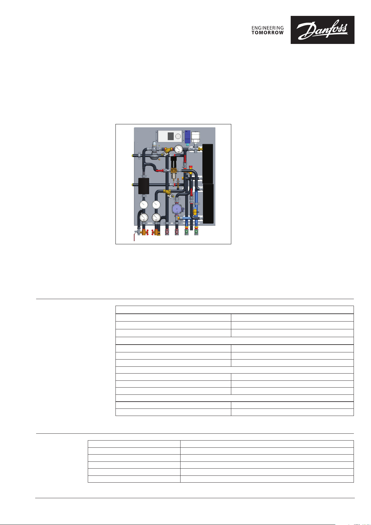
The DSP MINI is designed as a wall -mounted sta tion.
Each station is equipped with micro plate heat
exchangers for DHW and optional for heating manufactured by Danfoss, which significantly increase
substation performance and lifetime. All components are placed at the front of the station, which
makes it very easy to access them during maintenance or servicing. The mounting bracket significantly reduces the time required to mount the substation to the wall. The connections are predefined
and allow installers to prepare installation before
station is available on the site, which reduces the
time between deliver y and startup. Piping prepared
with automatic welding machines ensures th e highest possible welding quality.
DSP MINI is equipped with high quality Danfoss
components, which are tested, approved and optimized for safe and reliable operation:
• ECL Comfort 310 controller
• Motorized control valves
• AVTB self-acting temperature controller
• AVPB-F Differential pressure controller with flow
limitation
• Brazed MicroPlate™ Heat exchanger, XB06
• Primary side polyurethane insulation according
50% ENEV 2013
• Metal box with door
Operating parameters
Materials
Primary side
Maximum temperature 95°C
Maximum pressure 10 bar (g)
Connection DN 20 / Rp ¾”
Heating
Maximum temperature* 95°C
Maximum pressure* 10 bar (g)
Connection DN 20 / Rp ¾”
Domestic Hot Water
Maximum temperature 95°C
Maximum pressure 10 bar (g)
Connection DN 20 / Rp ¾”
Max dimensions (mm)
Width ⁄ Height ⁄ Depth 770 / 1000 / 330 mm
Weight (incl. packing) max. 80 kg
* In case of floor heating with heat exchanger the maximum
temperature is 50 °C and the maximum pressure is 3 bar(g)
Pipes, fittings, valves (primary side) P235GH, CuSn5ZnPb (Rg5), Red bronze (Rg5), brass MS58 (nickel plated)
Pipes, fittings, valves (heating side) P235GH , EN - GJL-150 (GG15)
Pipes, fittings, valves (DHW side) 1.4404, 1.4301, CW617N
Heat exchanger 1.4404 with Cu brazed
Insulation (heat exchanger) PU foam (λ=0.035 W/mK)
Insulation (piping primary side) PU foam (λ<0.025 W/mK)
© Danfoss | 2020.01
AI246186498258en-010202 | 1
Page 2
Data Sheet DSP MINI a Danfoss Platform for Flensburg Secondary Network
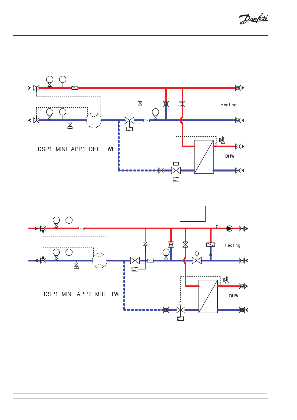
Circuit diagram
2
1
3
2
3
1
TIPI
18
TIPI
18
Approval number
FL-S-DL37-U-D-17/11
2
3
1
TIPI
18
4
3xDN 5xDN
5
6
4
15
10
7
15
2
PI
3
4
17
11
21
22
17
ECL
310
A230
13
25
15
16
23
16
15
12
2
3
1
TIPI
3xDN 5xDN
18
5
Approval number
FL-S-DL37-R-D-17/11
1 Ball valve with M10
sensor connection
2 Manometer
3 Manovalve
4 Strainer
5 Drain valve
6 Insert energy meter
7 Pressure controller AVPB-F
10
6
7
8 Control valve VM2
9 Heat exchanger
10 Shut off valve 6 mm
11 Temperature controller AVTB
12 Pump
13 Heat exchanger
14 Safety valve
15 Ball valve
15
17
PI
2
4
3
8
17
11
13
28
15
16
23
16
16 Ball valve DVGW
17 Ball valve
18 Bimetal thermometer
21 ECL
22 ECL application key
23 Safety valve
25 Temperature sensor
27 Safety temperature monitor (STW)
28 Check valve
2 | © Danfoss | 2020.01
AI246186498258en-010202
Page 3

Data Sheet DSP MINI a Danfoss Platform for Flensburg Secondary Network
21
ECL
22
2
3
1
TIPI
4
18
310
A230
25
27
15
12
2
3
1
TIPI
18
5
Approval number
FL-S-DL37-R/FB-D-17/11
2
1
3
2
3
1
TIPI
4
18
TIPI
18
5
3xDN
3xDN 5xDN
5xDN
6
6
10
7
10
4
7
15
2
PI
4
3
15
PI
2
3
17
21
22
17
17
11
ECL
310
A230
8
28
15
8
16
23
27
16
15
12
15
16
13
25
14
9
23
Approval number
FL-S-DL37-R/FB/WT-D-17/11
1 Ball valve with M10
sensor connection
2 Manometer
3 Manovalve
4 Strainer
5 Drain valve
6 Insert energy meter
7 Pressure controller AVPB-F
AI246186498258en-010202
17
8 Control valve VM2
9 Heat exchanger
10 Shut off valve 6 mm
11 Temperature controller AVTB
12 Pump
13 Heat exchanger
14 Safety valve
15 Ball valve
13
11
16 Ball valve DVGW
17 Ball valve
18 Bimetal thermometer
21 ECL
22 ECL application key
23 Safety valve
25 Temperature sensor
27 Safety temperature monitor (STW)
28 Check valve
© Danfoss | 2020.01 | 3
16
Page 4

Data Sheet DSP MINI a Danfoss Platform for Flensburg Secondary Network
2
3
1
2
3
1
Approval number
FL-S-KP-U-D-17/11
2
3
1
TIPI
18
TIPI
18
TIPI
18
4
3xDN
5xDN
10
15
2
PI
4
3
15
15
1717
5
4
6
7
21
ECL
22
310
A230
25
15
12
1
Approval number
FL-S-KP-R-D-17/11
1 Ball valve with M10
sensor connection
2 Manometer
3 Manovalve
4 Strainer
5 Drain valve
6 Insert energy meter
7 Pressure controller AVPB-F
4 | © Danfoss | 2020.01
10
2
3
TIPI
3xDN 5xDN
18
5
6
2
3
8 Control valve VM2
9 Heat exchanger
10 Shut off valve 6 mm
11 Temperature controller AVTB
12 Pump
13 Heat exchanger
14 Safety valve
15 Ball valve
15
PI
8
17
17
28
15
16 Ball valve DVGW
17 Ball valve
18 Bimetal thermometer
21 ECL
22 ECL application key
23 Safety valve
25 Temperature sensor
27 Safety temperature monitor (STW)
28 Check valve
AI246186498258en-010202
Page 5

Data Sheet DSP MINI a Danfoss Platform for Flensburg Secondary Network
21
ECL
22
2
3
1
TIPI
4
18
310
A230
25
27
15
12
2
3
1
TIPI
18
Approval number
FL-S-KP-R/FB-D-17/11
2
1
3
2
3
1
TIPI
18
TIPI
18
Approval number
FL-S-KP-R/FB/WT-D-17/11
1 Ball valve with M10
sensor connection
2 Manometer
3 Manovalve
4 Strainer
5 Drain valve
3xDN
5
4
3xDN 5xDN
5
6
6
10
PI
2
4
2
3
17
3
17
15
PI
17
5xDN
10
4
7
6 Insert energy meter
7 Pressure controller AVPB-F
8 Control valve VM2
9 Heat exchanger
10 Shut off valve 6 mm
11 Temperature controller AVTB
12 Pump
13 Heat exchanger
14 Safety valve
15
21
22
28
8
17
ECL
310
A230
8
15 Ball valve
16 Ball valve DVGW
17 Ball valve
18 Bimetal thermometer
21 ECL
22 ECL application key
23 Safety valve
25 Temperature sensor
27 Safety temperature monitor (STW)
28 Check valve
25
14
27
9
15
15
12
15
Function
AI246186498258en-010202
The DSP Mini substation is the connecting part
between the h eat supplier and the consumer of the
heating and domestic hot water.
The task of the substation is to adapt the heat condition suitable for the consumer and meet the
demand from the heat supplier and consumer.
The water is coming from the district heating utility
and is fed into the station at the appropriate pressure and temperature. This can be higher in winter
and lower in the summer. The district heating water
flows in the primary fl ow through the shut-off valves
and the strainer. Pressure gauges and thermom eters
are installed in the flow and return to detect the
pressure and temperature.
Depending on the variant, the connection of the
secondary side (heating) is carried out directly or
indirectly (via heat exchanger).
Furthermore, on the primary side, in the flow circuit
we have a control valve, depending on the variant,
control valves are used to adapt the heat condi tions
(secondary temperature) by controling the flow of
district heating water. The input s are comming from
using our Danfoss ECL Comfort 310 controller with
weather compensating function.
The district heating water then flows back to the
district heating supply via the primary return
through the shut-off valves and the strainer. On the
primary side, high tem perature connections for radi
ator heating or similar are used depending on the
application selected.
In the secondary circuit, a circulating pump distributes the heating water to the heating devices, this
is available depending on the application.
If the application selected has domestic hot water
production included, this is connected to the primary side and is prepare via a heat exchanger and
with a self-acting control valve.
To limit the flow of primary district heating water,
a flow limiter with integrated differential pressure
control is provided in the return of th e primary side,
here the maximum flow from the contract can be
adjusted. To measure the energy consumed, an
insert for a heat meter is available and M10 connections are provided in the primary side ball valves.
© Danfoss | 2020.01 | 5
-
Page 6

Data Sheet DSP MINI a Danfoss Platform for Flensburg Secondary Network
205
305
395
485
575
530
128
173
Capacity, weight and dimensions
Code Description
Typ e
Capacity
[kW]
Heat exchanger Pipe diameter
HE DHW HE DHW DH HE DHW kPa
146G0000
1
146G0001
2
146G0002
3
146G0003
4
5
146G0004
146G0005
6
146G0006
7
146G0007
8
* Calculated with 15 deg ΔT (40/65 °C)
** Calculated with 10 deg ΔT (25/35 °C)
DSP1 MINI APP1 DHE TWE 14*
DSP1 MINI APP2 MHE TWE 14*
DSP1 MINI APP3 FBH TWE 10* *
DSP2 MINI APP4 FBH TWE 10* *
37***
37***
37***
37***
n/a XB06H+-1-30
n/a XB06H+-1-30 65 66* FL-S-DL37-R-D-17/11
n/a XB06H+-1-30 65 65** FL-S-DL37-R/FB-D-17/11
XB06L-1-10 XB06H+-1-30 70 55**
DSP0 MINI APP5 DHE – 14* – n/a n/a 50 18**** FL-S-KP-U-D-17/11
DSP0 MINI APP6 MHE – 14* – n/a n/a 55 66* FL-S-KP-R-D-17/11
DSP0 MINI APP7 FBH – 10** – n/a n/a 55 65** FL-S-KP-R/FB-D-17/11
DSP1 MINI APP8 FBH – 10** – XB0 6L-1-10 n/a 60 55** FL-S-KP-R/FB/WT-D-17/11
*** Calculated with 40 deg ΔT (10/50 °C)
**** No pump is available in this application
DSP 1 MINI APP1 DHE TWE
Typ e No. of hex Application no Type of heating Type of DHW
MINI APP1 DHE = Direct heating TWE = Instantaneus
MINI APP2 FBH = Floor heating – = Connections
MINI APP3 MHE = Mixing heating
MINI APP4
MINI APP5
MINI APP6
MINI APP7
MINI APP8
DN 20 / R p ¾”
Max
(kg)
Heating Dp
available
approval number
Weight
60 18**** FL-S-DL37-U-D-17/11
FL-S-DL37-R/FB/WT-D-17/11
95
83
72
0
0
45
90
766
755
908
Configuration Contact the sales staff responsible for additional
details and a quotation for the DSP MINI.
290
Radiator heating return
Radiator heating supply
Drain valve
Primary out
Primary in
998
MAG
Heating return
Heating supply
Domestic hot water
Drain pipes
Cold water
6 | © Danfoss | DHS-SMDBT/PL | 2020.01
AI246186498258en-010202
 Loading...