

Page 1
Data sheet
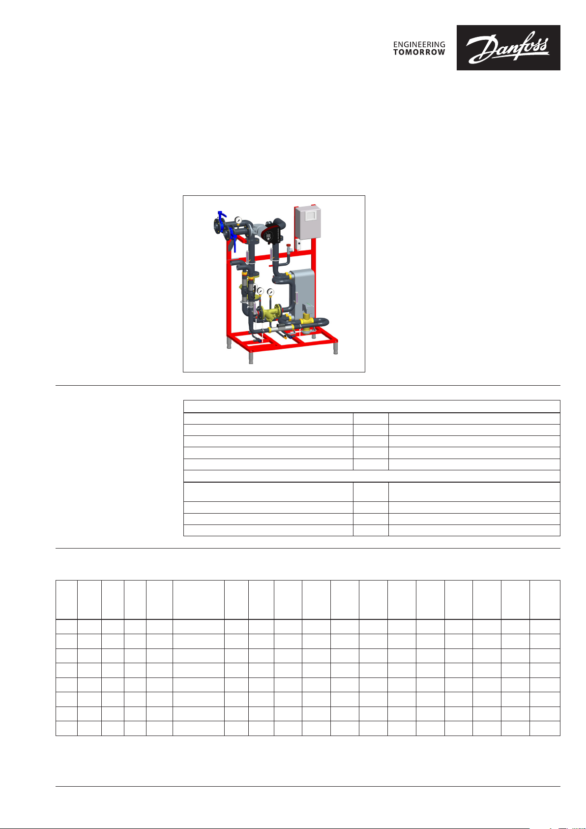
Danfoss DH Standard Welded Stations
Type DSP 1 MAXI CEE
General description and
application
Maximum operating
parameters
District heating transfer stations provide the link
between district heating suppliers and customers’
systems. They incorporate the necessary equipment to tailor the supplied heat to the needs of
the object premises as specied in the heating
supply contract. In this they need to comply with
all applicable standards and with the supplier’s
technical connection conditions.Indirect connections (in which district heating and in-house systems are hydraulically isolated)incorporate components to separate the systems (heat exchanger),
to limit the ow volume to that specied in the
contract, regulate the secondary supply temperature and measure the energy consumption. The
system described here is a standard type in which
one of dierent types of pump modules and different options can be connected on the secondary.
Thus, this system is especially suitable for District
Heating applications.
Primary
Maximum permissible supply temperature, primary
Maximum permissible operating pressure, primary PZP 16 bar (g)
Rated pressure, primary PN 16
Maximum permissible pressure dierential, primary
Maximum permissible ow volume, primary VPP 10,0 m3/h for w <= 1,5 m/s
TVP 130°C / (150 °C for material design components)
DPP 12 bar (PN16)
Secondary
Maximum permissible supply temperature,
secondary
Maximum permissible operating pressure, secondary
Rated pressure, secondary PN 10
Maximum permissible ow volume, secondary VPS 19,5 m3/h for w <= 1,5 m/s
TVS 100 °C
PZS 3 bar(g)
Technical data
type
no.
VPP
max.
[m3/h]
DN
prim.
QP
[m3/h]
AVQM
KVS
[m3/h]
HEX
type
VPS
max.
[m3/h]DNsec.
max.
dpp*
[kPa]
max.
dpp**
[kPa]
max.
dps***
[kPa]D [mm]W[mm]H[mm]B[mm]A[mm]
mass
[kg]
exp.
vessel
[l]
01 3 25 3 6,3 XB12 H 90 4,5 32 51 60 25 750 1150 1670 1038 140 9 131 150
02 3,5 32 3,5 8 XB12 M 110 6,2 32 54 59 21 750 1150 1670 1038 140 9 136 200
11 6 32 6 12, 5 XB52 M 50 7,1 40 69 81 25 750 1150 1670 1038 1409 144 300
12 6 32 6 12,5 XB52 M 70 11, 5 50 65 79 23 750 115 0 1670 1038 1409 153 500
21 8,2 40 10 16 XB59 M 80 11, 5 65 64 70 19 750 1150 1670 1038 1423 166 500
22 8,2 40 10 16 XB59 M 110 15, 8 65 63 69 24 750 115 0 1670 1038 1423 175 750
31 10 50 10 20 XB59 M 110 15, 8 65 57 66 33 750 115 0 1670 1038 1443 184 750
32 10 50 10 20 XB59 M 140 19,3 65 61 72 31 750 115 0 1670 1038 1443 195 750
* without heatmeter (HM) / include insert
** include heatmeter (HM) SonoMeter 40, battery, M bus
*** inside station
exp. vessel is not included. The intent is only recommended. Please check your conditions.
© Danfoss | 2022.03 AI118786455585en-010301 | 1
Page 2
Data sheet Danfoss DH Standard Welded Stations type DSP 1 MAXI CEE
Materials
Function
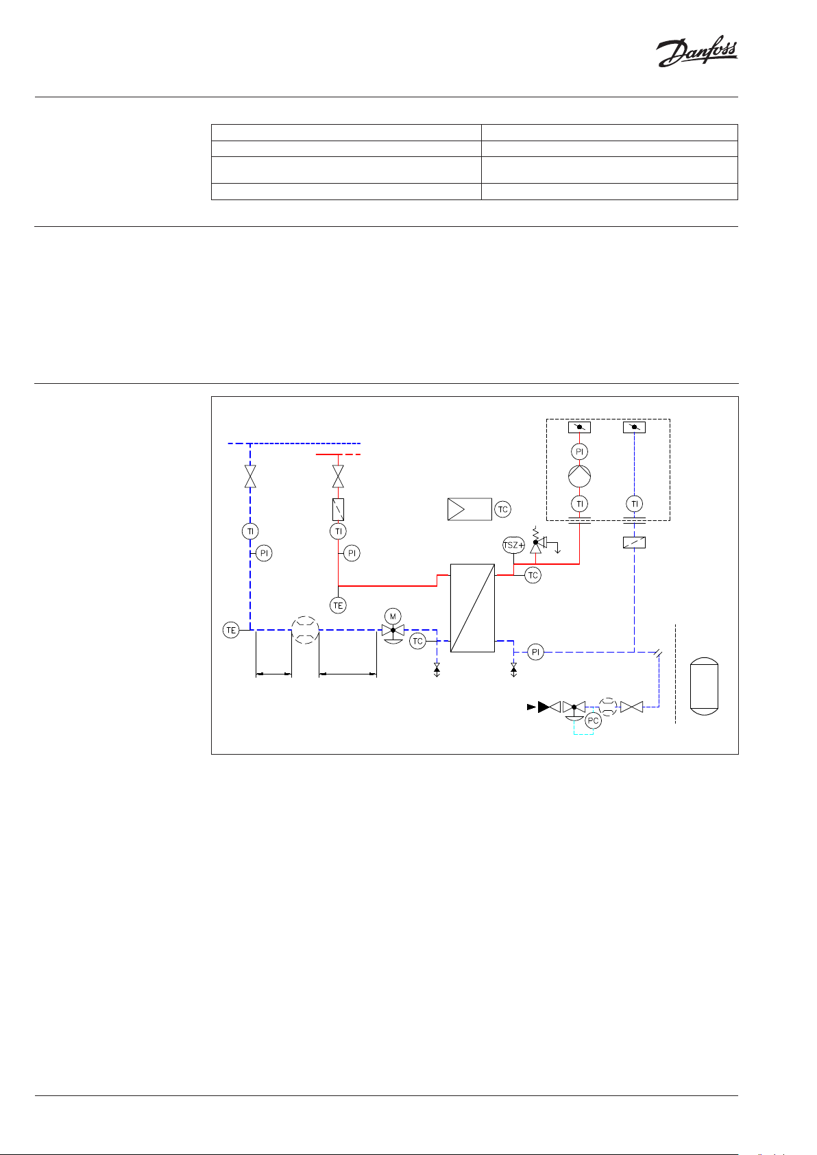
Circuit diagram
Pipes and pipe ttings, anges, threaded nuts P235GH-TC1, C22.8, CuSn5Pb5Zn5-C (RG-5)
Heat exchanger 1.4404 with CU brazing compound
Fittings CuSn5Pb5Zn5-C (RG-5), ST37.0,
Insulation PU-Hardfoam, black, λ = 0,027 W/mK
Hot water drawn from the pipeline of the local or
district heating supply company is fed into the
station at an appropriate temperature and pressure,
EN-GJS-400-18-LT (GGG40.3)
There will also be regulatory equipment in the
return lines of the primar y as specied by the circuit
design.
which may be higher in winter than in summer.
The cooled heating water then ows back to the
In the primary supply line this hot water will ow
through a shut-o valve and a dirt trap / strainer.
local or district heating supply company via the
primary return pipe.
The supply and return lines will incorporate athermometer and a manometer to register the temperature and pressure.
200
220
400
430
M1
On secondary side dierent types of pump modules
and dierent options can be connected.
210
440
HPU
410
230
10
500
DSL
S1
STW
100
S3
40
5DN3DN
DSP 1 MAXI
200 Shut-o device for primary (left/right conn.)
220 Dirt trap / strainer
430 Manometer
400 Thermometer
40 Insert / optional Heatmeter
20 Motorized Combi (Control) valve
M1 Electrical actuator
S5 Return temperature limiter primary
270 High-pressure drain valve
10 Heat exchanger
Optional sheet metal harcover (accessory)
DSL
HPU Heating Pump
210 Shut-o device secondary
290 Relling line (accessories)
20
S5
270 280
MAG
440
EXP
290
100 Safety valve
S3 Supply temperature sensor secondary
EXP Expansion Vessel (delivered by costumer)
MAG Pressure retention connector
280 Drain valve
230 Dirt trap / strainer
440 Manometer
500 Electronic controller
S1 Outdoor sensor
410 Thermometer
440 Manometer
2 | AI118786455585en-010301 © Danfoss | 2022.03
Page 3

Data sheet Danfoss DH Standard Welded Stations type DSP 1 MAXI CEE
A
Type designation
Type designation
for Pump Module
Dimensions
DSP 1 MAXI - PD
Base type P=Electrical box Typ e No. LT:
Controller Danfoss see Page 1 HM SonoMeter 40 QP ..
D = ECL310 S035 = SonoMeter 40 QP 3,5 battery
I260 = Insert 260 mm
-
11 LT S100
PN16/130 °C
DSL - 40 –120 F - MG1
Pump module Pump properties Type of pump
MG1 = MAGNA1
MG3 = MAGNA3
Lenght of insert for HM or
S060 = SonoMeter 40 QP 6,0 battery
S100 = SonoMeter 40 QP 10,0 battery
I300 = Insert 300 mm
B
148
H
AI118786455585en-010301 | 3© Danfoss | 2022.03
Page 4

Data sheet Danfoss DH Standard Welded Stations type DSP 1 MAXI CEE
Capacity range
Temperature
programs
Capacities [kW] 100 125 150 175 200 300 350 400 450
Temperatures
primary / secondary [°C]
130 -> 75 / 90 < 70 01 02 11 12 12 22 22 32
120 -> 65 / 80 < 60 01 02 11 12 12 22 22 32
110 -> 60 / 75 < 55 01 02 11 12 12 22 22 32
110 -> 55 / 70 < 50 01 02 11 12 12 22 22 32
90 -> 60 / 75 < 55 01 02 11 11 12 22 32
use impossible
Ordering codes
Standard substation Accesory
Codes Typ e
861L1745 DSP 1 MAXI-PD-01 LT S035 CEE 01
861L0880 DSP 1 MAXI-PD-01 LT I260 01
861L1746 DSP 1 MAXI-PD-02 LT S035 CEE 02
861L0881 DSP 1 MAXI-PD-02 LT I260 02
861L1747 DSP 1 MAXI-PD-11 LT S060 CEE 11
861L0882 DSP 1 MAXI-PD-11 LT I260 11
861L1748 DSP 1 MAXI-PD-12 LT S060 CEE 12
861L0883 DSP 1 MAXI-PD-12 LT I260 12
861L1749 DSP 1 MAXI-PD-21 LT S100 CEE 21
00 4F4831
DSP 1 MAXI-PD-21 LT I300 21
861L1750 DSP 1 MAXI-PD-22 LT S100 CEE 22
004F4832
DSP 1 MAXI-PD-22 LT I300 22
861L1751 DSP 1 MAXI-PD-31 LT S100 CEE 31
004F4833
DSP 1 MAXI-PD-31 LT I300 31
861L1752 DSP 1 MAXI-PD-32 LT S100 CEE 32
004F4834
DSP 1 MAXI-PD-32 LT I300 32
Typ e
no.
Typ e
Module pump Sheet hardcover
Codes Description Codes Description
861L1396 /
861L13 97
861L1398 /
861L13 9 9
861L1400 /
861L1401
004F5908 /
144G4157
004F5909 /
144G4158
DSL 25-120F MG1 /
DSL 25-120F MG3
DSL 32-120F MG1/
DSL 32-120F MG3
DSL 40-120F MG1 /
DSL 40-120F MG3
DSL 50-120F MG3 /
DSL 50-120F MG1
DSL 50-150F MG3 /
DSL 50-150F MG1
861L0902
00 4F4931
DSP1 MAXI
BOX 01-12
DSP1 MAXI
BOX 21-32
Codes Description
004F5910
Reling line: -2 pcs. Ball valves valves DN25 +
for expansion vessel
Pressure reducer + owmeter+connection port
Example for ordering:
substation 210 kW, type 12 without heatmeter
DSP 1 MAXI DSP 1 MAXI-PD-12 LT I260
Type 12 861L0883
Application Key 087H3802 (Application Key need to be ordered separate.
Not included in station)
Pump Module
DSL 40-120F MG3 861L14 01
Optional
Relling line 004F5910
© Danfoss | DCS-SGDPT/PL | 2022.034 | AI118786455585en-010301
 Loading...