

Page 1
Application Guide
Scroll compressors
DSF090 to DSF530
Single and manifold, 50-60 Hz - R32
www.danfoss.com
Page 2
Scroll compressors, DSF090 to DSF530 | Contents
Contents
Safety and warnings 5
Introduction 6
Product description 6
Cut Away DSF090-200 6
Cut away DSF 270-530 7
How do IDVs work? 7
Product identication 8
Name Plate 8
Nomenclature 8
Compressors serial number 9
Certicates, declarations, and approvals 10
Low voltage directive 2014/35/EU 10
Machines directive 2006/42/EC 10
Pressure equipment directive 2014/68/EU 10
Internal free volume 10
Refrigerants 11
General information 11
R32 11
Technical specication 12
50-60 Hz data, Single compressor 12
Performance data 13
R32 50-60 Hz, Single compressor 13
Tandem and trio performances 13
Sound and vibration data 14
Compressor sound radiation 14
Mechanical vibrations 15
Operating envelope data 16
Operating envelope 16
Dimensions 18
Single compressors 18
Tandem assemblies 19
© Danfoss | Climate Solutions | 2021.10 AB309735209512en-000401 | 2
Page 3
Scroll compressors, DSF090 to DSF530 | Contents
Trio assemblies 20
Mechanical connections 22
Connection details 22
Design compressor mounting 22
Design piping 26
Electrical connections 33
Wiring connections 33
Electrical specications 34
Application 39
Manage oil in the circuit 39
Manage sound and vibration 39
Manage operating envelope 40
Manage superheat 42
Manage o cycle migration 44
Power supply and electrical protection 47
Control logic 49
Reduce moisture in the system 51
Assembly line procedure 52
Commissioning 55
Dismantle and disposal 56
Packaging 57
Single pack 57
Industrial pack 57
Ordering 58
Compressor code numbers 58
Single pack 58
Industrial pack 58
Accessories and spare parts 60
Gaskets 60
Solder sleeve 60
Rotolock nut 60
Motor protection modules 60
Surface sump heaters 61
Mounting hardware 61
Lubricant 61
© Danfoss | Climate Solutions | 2021.10 AB309735209512en-000401 | 3
Page 4

Scroll compressors, DSF090 to DSF530 | Contents
Terminal boxes, covers and T-block connectors 62
Acoustic hoods 62
Miscellaneous 62
Tandem kits 62
Trio kits 63
Online support 64
© Danfoss | Climate Solutions | 2021.10 AB309735209512en-000401 | 4
Page 5

Scroll compressors, DSF090 to DSF530 | Safety and warnings
Safety and warnings
Danfoss compressors are designed and manufactured according to the state of the art and to valid European and US
regulations. Particular emphasis has been placed on safety and reliability. Related instructions are highlighted with
the following icons:
This icon indicates instructions to avoid safety risk.
This icon indicates instructions to avoid reliability risk.
The purpose of this guideline is to help customers qualify compressors in the unit. You are strongly advise to follow
these instructions. For any deviation from the guidelines, please contact Danfoss Technical Support. In any case,
Danfoss accepts no liability as a result of the improper integration of the compressor into the unit by the system
manufacturer.
© Danfoss | Climate Solutions | 2021.10 AB309735209512en-000401 | 5
Page 6
1
2
4
5
6
3
CC-000005
12345
6
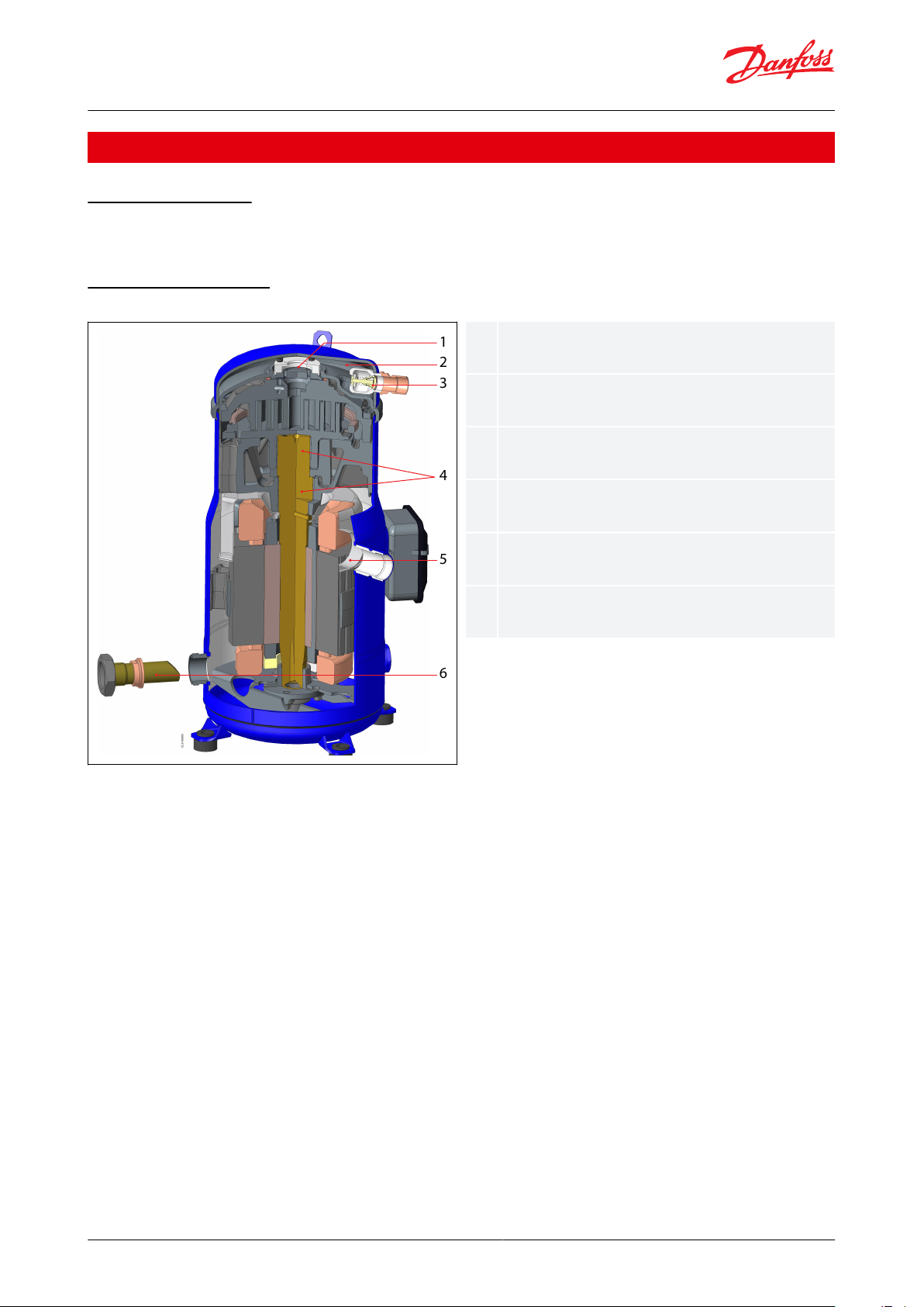
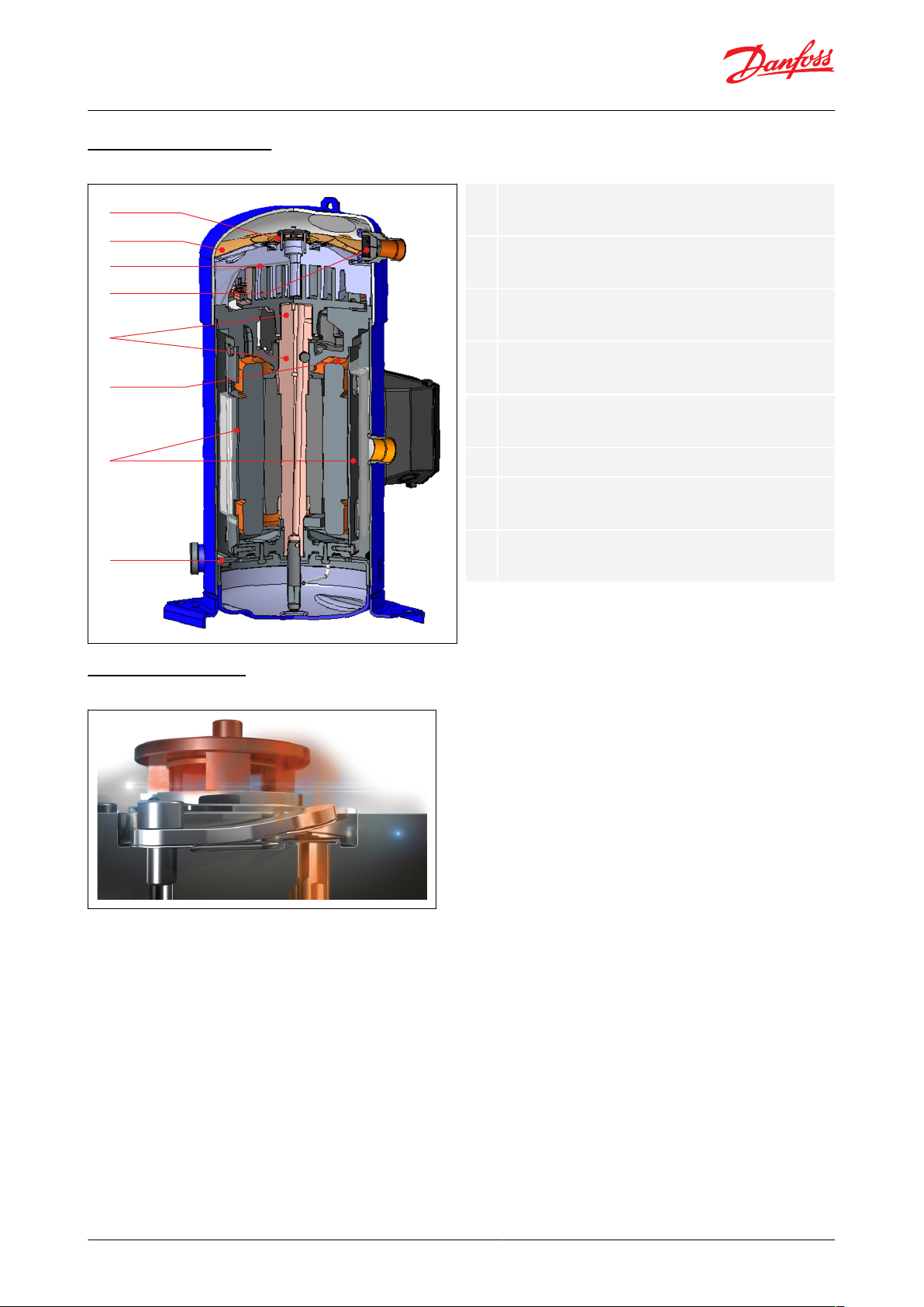
Intermediate discharge valves (IDVs) increase
seasonal eciency
Heat shield lowers the heat transfer between
discharge and suction gas and the sound level
Internal Non Return Valve (INRV) prevents
excessive leak rate from high pressure side
Lead free polymer bearings improve behavior
under poor lubrication conditions
Patented motor cap for optimal motor cooling and
higher resistance to liquid slugging
Organ pipe masters oil circulation in manifold
conguration.
Scroll compressors, DSF090 to DSF530 | Introduction
Introduction
Product description
DSF series scroll compressor benet from an improved design to achieve the highest eciency and increased life
time.
Cut Away DSF090-200
Figure 1: Cut Away DSF090-200
© Danfoss | Climate Solutions | 2021.10 AB309735209512en-000401 | 6
Page 7
1
2
3
4
5
6
7
8
1234567
8
Intermediate discharge valves (IDVs) increase
seasonal eciency
Heat shield lowers the heat transfer between
discharge and suction gas and the sound level
Integrated discharge gas temperature protection
(DGT)
Internal Non Return Valve (INRV) prevents
excessive leak rate from high pressure side
Lead free polymer bearings improve behavior
under poor lubrication conditions
Patented motor cap for optimal motor cooling
Patented gas path ow with gas intake design
induce higher resistance to liquid slugging
Organ pipe masters oil circulation in manifold
conguration.
Scroll compressors, DSF090 to DSF530 | Introduction
Cut away DSF 270-530
Figure 2: Cut Away DSF 270-530
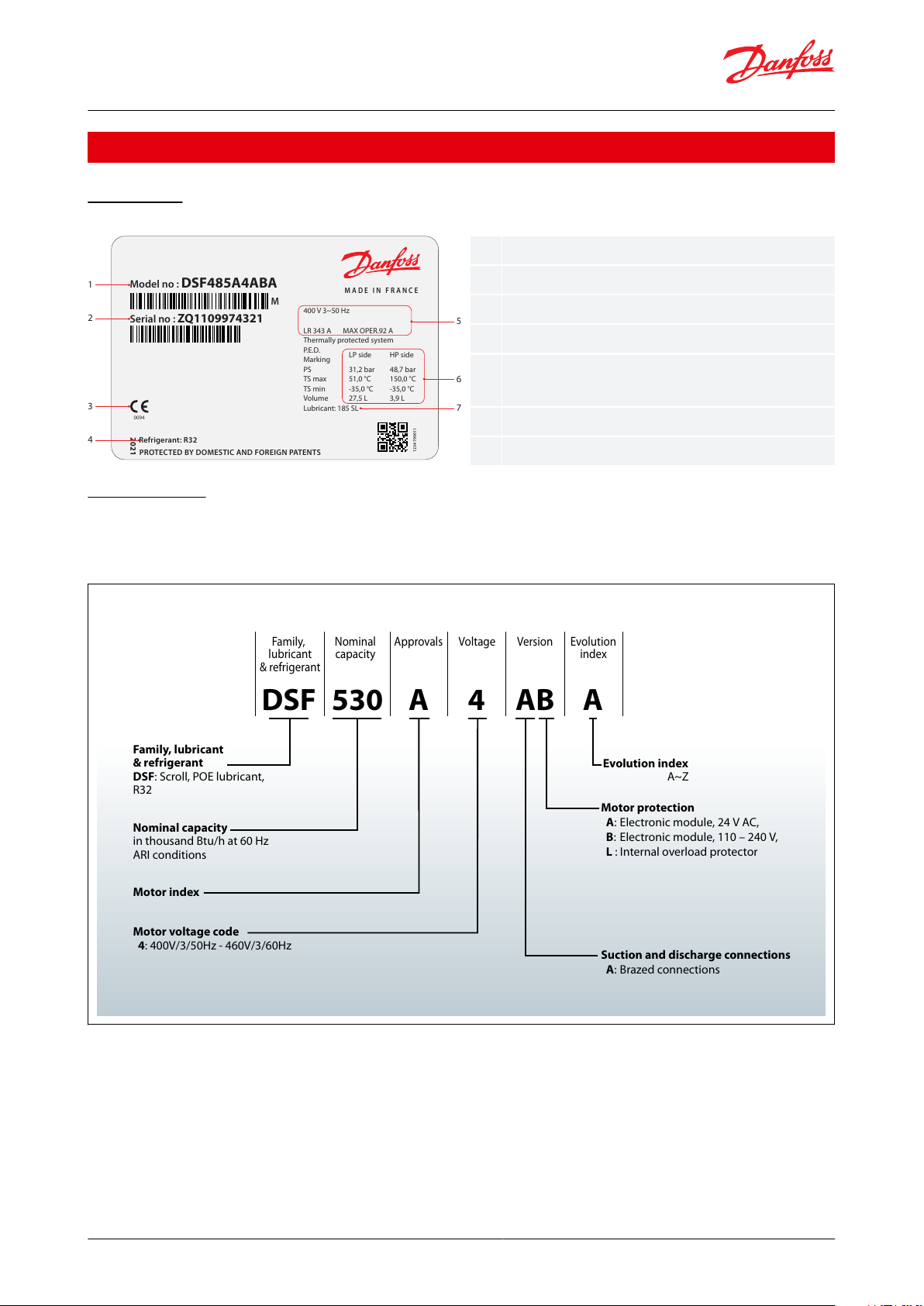
How do IDVs work?
Figure 3: Intermediate Discharge Valve (IDV)
Danfoss Intermediate Discharge Valves (IDVs) are located close to the discharge side of the compressor. They reduce
excessive compression of refrigerant under part-load conditions while maintaining the same cooling capacity. The
IDVs open when discharge pressure falls below the built-in optimization point. They adapt the eort of the motor to
the varying load and pressure conditions in the system, thus reducing the eort of the motor and its electrical
consumption and improving the system’s seasonal energy eciency.
© Danfoss | Climate Solutions | 2021.10 AB309735209512en-000401 | 7
Page 8
M A D E I N F R A N C E
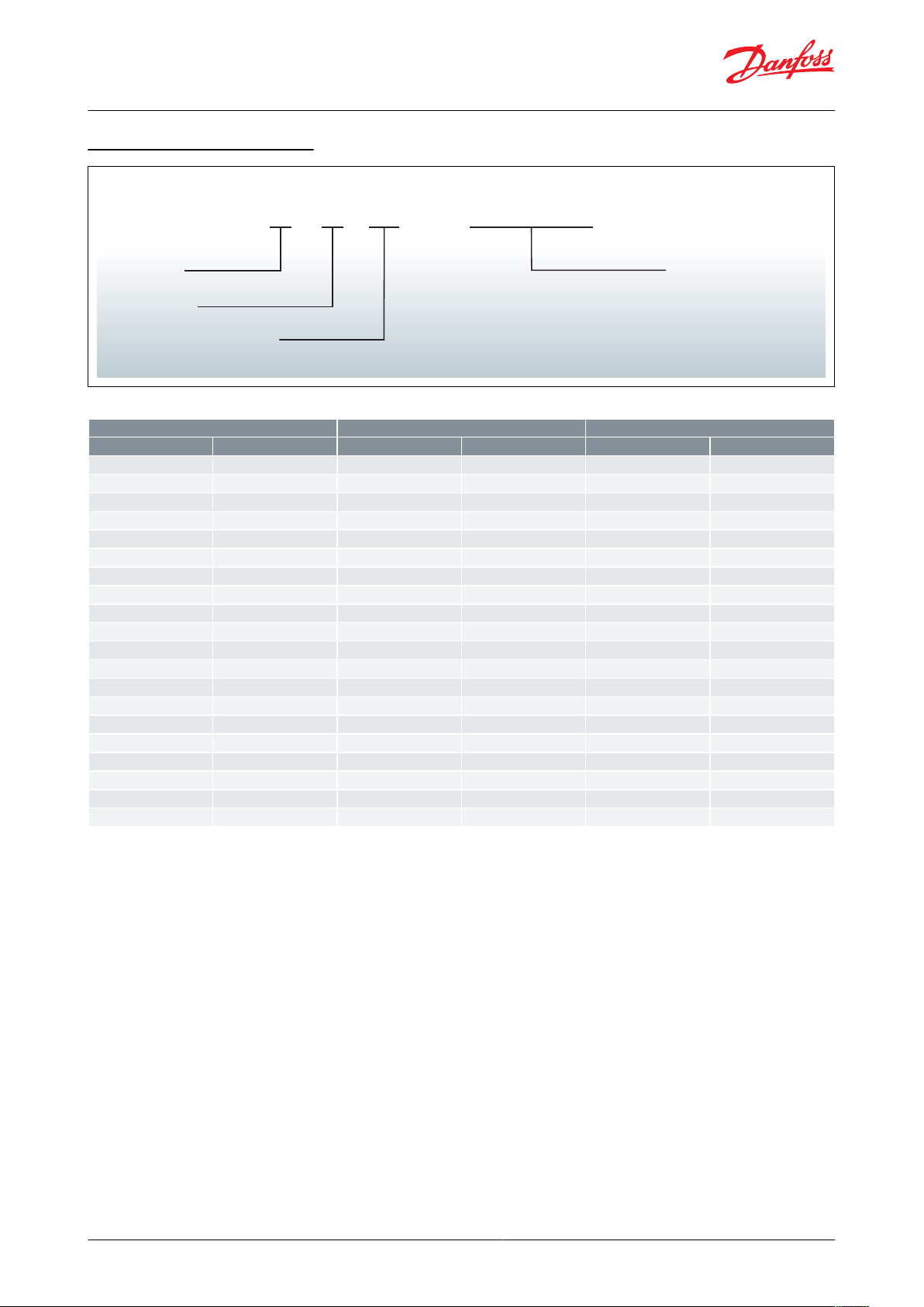
Model no : DSF485A4ABA
Serial no : ZQ1109974321
400 V 3~50 Hz
Thermally protected system
P.E.D.
Marking
LP side HP side
PS 31,2 bar 48,7 bar
TS max 51,0 °C 150,0 °C
TS min -35,0 °C -35,0 °C
Volume 27,5 L 3,9 L
Lubricant: 185 SL
M
2021
Refrige rant: R32
12347 9901 1
PROTEC TED BY DOM ESTIC AND FOREIGN PATENTS
0094
1
5
6
7
2
3
4
LR 343 A MAX OPER.92 A
123
4567Model number
Serial number
Approvals
Refrigerant
Supply voltage, Starting current & Maximum
operating current
Housing service pressure
Factory charged lubricant
Family, lubricant
& refrigerant
DSF: Scroll, POE lubricant,
R32
Motor protection
A: Electronic module, 24 V AC,
B: Electronic module, 110 – 240 V,
L : Internal overload protector
Suction and discharge connections
A: Brazed connections
Family,
lubricant
& refrigerant
Nominal
capacity
Approvals Voltage Version Evolution
index
Evolution index
A~Z
A4DSF A AB530
Motor voltage code
4: 400V/3/50Hz - 460V/3/60Hz
Motor index
Nominal capacity
in thousand Btu/h at 60 Hz
ARI conditions
Scroll compressors, DSF090 to DSF530 | Product identication
Product identication
Name Plate
Figure 4: Name Plate
Nomenclature
Danfoss scroll compressor DSF for R32 is available as single compressor and can be assembled in tandem or trio
combinations. The example below presents the compressor nomenclature which equals the technical reference as
shown on the compressor nameplate. Code numbers for ordering are listed in section Ordering.
© Danfoss | Climate Solutions | 2021.10 AB309735209512en-000401 | 8
Page 9
Year code 8 Digit serial number
12345678A 25B
Plant assembly line code
Month code
Year code
Month code
Plant assembly line code
Year
Code
Month
Code
Plant
Code
1990, 2010
A
January
A
Trévoux, France
11
1991, 2011
B
February
B
1992, 2012
C
March
C
1993, 2013
D
April
D
Wuqing ,China
25
1994, 2014
E
May
E
1995, 2015
F
June
F
1996, 2016
G
July
G
1997, 2017
H
August
H
1998, 2018
J
September
J
1999, 2019
K
October
K
2000, 2020
L
November
L
2001, 2021
M
December
M
2002, 2022
N
2003, 2023
P
2004, 2024
Q
2005, 2025
R
2006, 2026
S
2007, 2027
T
2008, 2028
U
2009, 2029
V
Scroll compressors, DSF090 to DSF530 | Product identication
Compressors serial number
Table 1: Serial number code legend table
© Danfoss | Climate Solutions | 2021.10 AB309735209512en-000401 | 9
Page 10
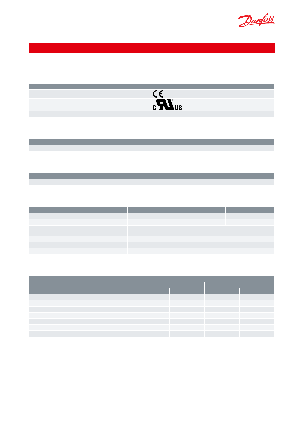
Approval and certicates
Certication logo
Models
CE0062 or CE0094 (European Directive)
All DSF models
UL (Underwriters Laboratories)
All DSF models
Other approvals / certicates
Contact Danfoss
Products
DSF models
Declaration of conformity
Contact Danfoss
Products
DSF models
Manufacturer’s declaration of incorporation
Contact Danfoss
Products
DSF090-200
DSF270-325
DSF485-530
Refrigerant
uids
Group 1
Group 1
Group 1
Category PED
III
III
IV
Maximum / Minimum temperature (Low side) - Ts
-35°C < Ts < 53°C
-31°F < Ts < 127°F
-35°C < Ts < 51°C
-31°F < Ts < 125.6°F
Maximum allowable pressure (Low side) - Ps
32.7bar(g) / 474psig
31.2 bar(g) / 452 psig
Maximum allowable pressure (High side) - Ps
48.7 bar(g) / 706 psig
Declaration of conformity
Contact Danfoss
Products
Internal free volume without oil
Low pressure side
High pressure side
Total
litre
cu.inch
litre
cu.inch
litre
cu.inch
DSF090-100
11.7
714
0.74312.4
757
DSF115-175
13.6
830
0.74314.3
873
DSF200
13.9
848
0.74314.6
891
DSF270
27.5
1678
2.9
177
30.4
1855
DSF325
27.1
1654
2.8
171
29.9
1825
DSF485
28.5
1739
3.9
238
32.4
1977
DSF530
28.5
1739
3.9
238
32.4
1977
Scroll compressors, DSF090 to DSF530 | Certicates, declarations, and approvals
Certicates, declarations, and approvals
DSF scroll compressors comply with the following approvals and certicates.
Certicates are listed on: Documentation for Commercial Compressor | Danfoss
Table 2: Approval and certicates
Low voltage directive 2014/35/EU
Table 3: Low voltage directive 2014/35/EU
Machines directive 2006/42/EC
Table 4: Machines directive 2006/42/EC
Pressure equipment directive 2014/68/EU
Table 5: Pressure equipment directive 2014/68/EU
Internal free volume
Table 6: Internal free volume
© Danfoss | Climate Solutions | 2021.10 AB309735209512en-000401 | 10
Page 11

Scroll compressors, DSF090 to DSF530 | Refrigerants
Refrigerants
General information
When choosing a refrigerant, dierent aspects must be taken into consideration:
• Legislation (now and in the future)
• Safety
• Application envelope in relation to expected running conditions
• Compressor capacity and eciency
• Compressor manufacturer recommendations & guidelines
Additional points could inuence the nal choice:
• Environmental considerations
• Standardisation of refrigerants and lubricants
• Refrigerant cost
• Refrigerant availability
R32
R32 is a pure HFC refrigerant with a zero Ozone Depletion Potential (ODP=0) and a low Global Warming Potential
(GWP: 677/AR5; 675/AR4).
R32 leads to higher discharge temperatures than R410A but it oers higher cooling capacities and better eciencies
compared to R410A.
R32 is classied A2L with low ammability properties. Please refer to European regulations and directives about the
use of refrigerant of the A2L safety group (EN378, EN60335). Outside Europe refer to the local regulation
© Danfoss | Climate Solutions | 2021.10 AB309735209512en-000401 | 11
Page 12

Model
Swept volume
Displacement (50 Hz)
(1)
Displacement (60 Hz)
(2)
Oil charge
Net weight
(3)
cm3/rev
cu.in/rev
m3/h
cu.ft/h
m3/h
cu.ft/h
dm
3
ozkglbs
DSF090
81.3
4.96
14.2
500
17.1
603
3.0
10258128
DSF100
88.4
5.39
15.4
544
18.6
657
3.0
10258128
DSF115
103.5
6.3218636
21.8
770
3.3
11364141
DSF130
116.9
7.13
20.3
717
24.6
869
3.3
11364141
DSF155
133
8.12
23.1
816
27.9
985
3.3
11367148
DSF175
151.7
9.26
26.4
932
31.9
1127
3.3
11369152
DSF200
170.3
10.39
29.6
1045
35.8
1264
3.6
123
71.5
158
DSF270
227.6
13.89
39.6
1398--
6.1
206
114
251
DSF325
276.2
16.85
48.1
1699--
6.1
206
117
258
DSF485
407.2
24.85
70.9
2502--
6.1
206
176
388
DSF530
442.6
27.01772719--
6.1
206
176
388
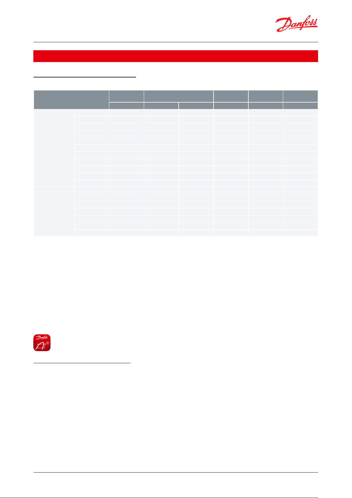
Scroll compressors, DSF090 to DSF530 | Technical specication
Technical specication
50-60 Hz data, Single compressor
Table 7: 50-60 Hz data, Single compressor
(1)
(1)
Displacement at nominal speed: 2900 rpm at 50 Hz
Displacement at nominal speed: 2900 rpm at 50 Hz
(2)
(2)
Displacement at nominal speed : 3500 rpm at 60 Hz
Displacement at nominal speed : 3500 rpm at 60 Hz
(3)
(3)
Net weight with oil charge
Net weight with oil charge
© Danfoss | Climate Solutions | 2021.10 AB309735209512en-000401 | 12
Page 13
Model
Nominal tons
60Hz
Nominal cooling capacity
Power input
COP
E.E.R.
TRWBtu/hkWW/W
Btu/h/W
50 Hz
DSF090
7.5
19958
68096
6.69
2.99
10.19
DSF100
8.5
21940
74860
7.13
3.08
10.50
DSF115
10
26349
89904
8.31
3.17
10.82
DSF130
11
29421
100384
9.19
3.20
10.93
DSF155
13
33772
115232
10.51
3.21
10.97
DSF175
15
39172
133655
12.07
3.24
11.07
DSF200
16.5
43329
147838
13.53
3.20
10.92
DSF270
-
60037
204853
17.98
3.34
11.40
DSF325
-
72501
247380
21.50
3.37
11.51
DSF485
-
107102
365443
31.67
3.38
11.54
DSF530
-
116998
399209
34.27
3.41
11.65
60 Hz
DSF090
7.5
26938
91911
8.68
3.10
10.59
DSF100
8.5
29362
100182
9.38
3.13
10.67
DSF115
10
34923
119157
10.79
3.24
11.04
DSF130
11
39465
134653
12.24
3.22
11.00
DSF155
13
45215
154273
13.82
3.27
11.16
DSF175
15
51618
176121
15.70
3.29
11.22
DSF200
16.5
57717
196932
17.63
3.27
11.17
Scroll compressors, DSF090 to DSF530 | Performance data
Performance data
R32 50-60 Hz, Single compressor
Table 8: 50-60 Hz R32, Single compressor
NOTE:
TR: Ton of Refrigeration,
COP: Coecient Of Performance
EER: Energy Eciency Ratio
Standard rating conditions for 50Hz: Evaporating temperature: 5°C (41°F), Condensing temperature: 50°C (122°F),
Superheat: 10K (18°F), Subcooling: 0K (0°F)
Standard rating conditions for 60Hz: Evaporating temperature: 7.2°C (45°F), Condensing temperature: 54.4°C (130°F),
Superheat: 11.1K (20°F), Subcooling: 8.3K (15°F)
Subject to modication without prior notication.
Data given for motor code 4 compressor with above conditions
For regular updates and detailed capacities, please refer to Coolselector®2.
Tandem and trio performances
The impact of manifolding on compressor performances depends widely of the customer system itself. Therefore, it
would be unrealistic to provide data that corresponds accurately to a particular system. In rst approach, to support
compressors selection at full load, the manifold performances can be considered as the sum of capacities of the
compressors composing the manifold. For better accuracy, the customer should integrate the appropriate weighing
coecients according to his system very pressure drops and part load levels.
© Danfoss | Climate Solutions | 2021.10 AB309735209512en-000401 | 13
Page 14

Compressor model
50 Hz
60 Hz
Acoustic hood code no.
Sound power, dB(A)
Attenuation, dB(A)
Sound power, dB(A)
Sound power, dB(A)
DSF09074-77--DSF10076-79--DSF115-17578-81--DSF20080-83--DSF270834--
120Z0768
DSF325834--
DSF485894--
DSF530894--
Scroll compressors, DSF090 to DSF530 | Sound and vibration data
Sound and vibration data
Typical sounds and vibrations in systems can be broken down into the following three categories:
• Sound radiation (through air)
• Mechanical vibrations (through parts and structure)
• Gas pulsation (through refrigerant)
The following sections focus on the causes and methods of mitigation for each of the above sources.
Compressor sound radiation
For sound radiating from the compressors, the emission path is air and the sound waves are travelling directly from
the machine in all directions.
Sound levels as follows:
• For compressors running alone:
Table 9: Compressor sound radiation
NOTE:
Sound power and attenuation are given at ARI conditions, measured in free space.
For compressors running simultaneously
The global sound level of “n” identical compressors is:
L
=Li+10 Log10 n
GLOBAL
Example for the trio
DSF810T = 3 × DSF270
L
=83dB(A)
DSF270
L
=83+10 Log10 3=87 . 8dB(A)
DSF810T
The global sound level of “n” dierent compressors with respectively Li sound level is:
L
GLOBAL
i = n
= 10
i = 1
log10(∑ 10
0.1
∗ Li)
Example for the tandem
DSF1180T=DSF325+DSF325+DSF530
L
DSF325
L
DSF1180T
=83dB(A),L
=10Log10(10
DSF530
=89dB(A)
0 . 1×83
+10
0 . 1×83
+10
0 . 1×89
)= 90 . 8dB(A)
© Danfoss | Climate Solutions | 2021.10 AB309735209512en-000401 | 14
Page 15

Scroll compressors, DSF090 to DSF530 | Sound and vibration data
Mechanical vibrations
A compressor generates some vibrations that propagate into the surrounding parts and structure. The vibration
level of a DSF compressor alone does not exceed 120 µm peak to peak for DSF090 to DSF200, and 154um peak to
peak for DSF270 to DSF530.. However, when system structure natural frequencies are close to running frequency,
vibrations are amplied due to resonance phenomenon.
A high vibration level is damageable for piping reliability and generates high sound levels.
© Danfoss | Climate Solutions | 2021.10 AB309735209512en-000401 | 15
Page 16
Condensing temperature (°C)
Condensing temperature (°F)
Evaporating temperature (°C)
Evaporating temperature (°F)
5
10
15
20
25
30
35
40
45
50
55
60
65
70
41
0
32
50
59
68
77
86
95
104
113
122
131
140
149
158
-30-35 -25 -20 -15 -10 -5 0 5 10 15 20 25 30
-22-31 -13 -4 5 14 23 32 41 50 59 68 77 86
S.H. = 5 K (9°F)
CC-000182
S.H. = 10 K (18°F)
Condensing temperature (°C)
Condensing temperature (°F)
Evaporating temperature (°C)
Evaporating temperature (°F)
5
10
15
20
25
30
35
40
45
50
55
60
65
70
41
0
32
50
59
68
77
86
95
104
113
122
131
140
149
158
-30-35 -25 -20 -15 -10 -5 0 5 10 15 20 25 30
-22-31 -13 -4 5 14 23 32 41 50 59 68 77 86
S.H. = 5 K (9°F)
CC-000183
S.H. = 10 K (18°F)
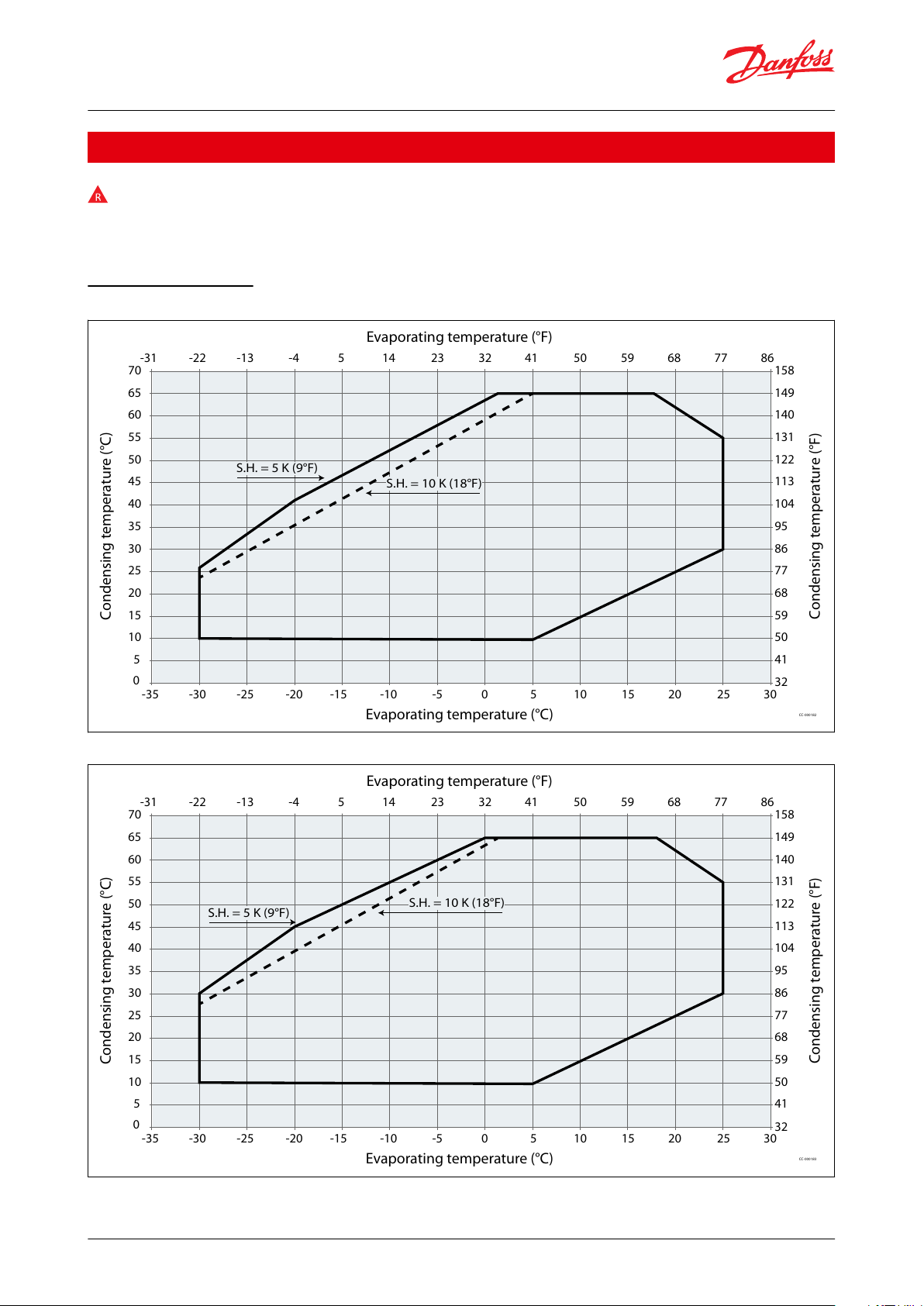
Scroll compressors, DSF090 to DSF530 | Operating envelope data
Operating envelope data
The Operating envelope data for DSF scroll compressors guarantees reliable operations of the compressor for
steady-state operation.
Steady-state operation envelope is valid for a suction superheat within 5K to 10K range at nominal Voltage.
Operating envelope
Figure 5: Operating envelope R32 DSF090 to DSF130
Figure 6: Operating envelope R32 DSF155 to DSF200
© Danfoss | Climate Solutions | 2021.10 AB309735209512en-000401 | 16
Page 17
Condensing temperature (°C)
Condensing temperature (°F)
Evaporating temperature (°C)
Evaporating temperature (°F)
5
10
15
20
25
30
35
40
45
50
55
60
65
70
41
0
32
50
59
68
77
86
95
104
113
122
131
140
149
158
-30-35 -25 -20 -15 -10 -5 0 5 10 15 20 25 30
-22-31 -13 -4 5 14 23 32 41 50 59 68 77 86
S.H. = 5 K (9°F)
CC-000543
S.H. = 10 K (18°F)
Pressure settings
R32
Working range high side
bar(g)
10 – 43
psig
145 – 624
Working range low side
bar(g)
1.7 – 15.9
psig
25 – 231
Maximum high pressure safety switch setting
bar(g)
44.4
psig
645
Minimum low pressure safety switch setting
bar(g)
1.5
psig
22
Minimum low pressure pump-down switch setting
bar(g)
1.5 bar below nominal evap. pressure with minimum of 1.7 bar(g)
psig
22 psi below nominal evap. pressure with minimum of 25 psig
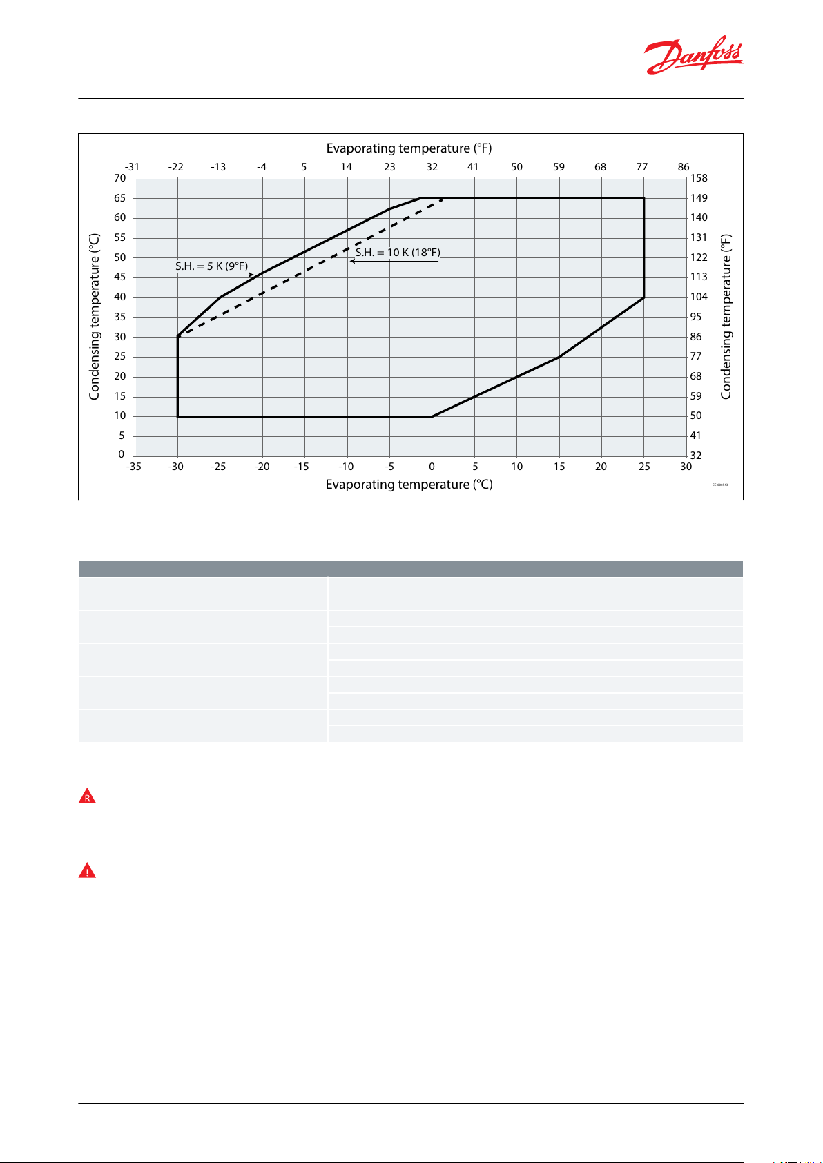
Scroll compressors, DSF090 to DSF530 | Operating envelope data
Figure 7: Operating envelope R32 DSF270 to DSF530
Pressure settings
Table 10: Pressure settings
High and low pressure protection
Low-pressure (LP) and high-pressure (HP) safety switches must never be bypassed nor delayed and must stop all
the compressors.
LP switch auto restart must be limited to 5 times within 12 hours.
HP safety switch must be reset manually.
Depending on application operating envelope, you must dene HP and LP limits within operating envelope and
pressure setting table above.
© Danfoss | Climate Solutions | 2021.10 AB309735209512en-000401 | 17
Page 18
Ø D
H1
Ø19.05mm
(0.75 inch)
L3
L2
190.5mm
(7.5 inch)
190.5mm
(7.5 inch)
L1
30°
H2
H
30°
CC-000055
Ø D
H
H2
H1
L1
L3
L2
8556208
H
H2
H1
Ø D
L2
L3
L1
8556199
Compressor
model
DHH1H2L1L2L3
Outline drawing no.
mm
inchmminchmminchmminchmminchmminchmminch
DSF090-100
243
9.57
485
19.09
235
9.25
451
17.76
180
7.09
230
9.06
230
9.0618560176
DSF115-175
243
9.57
542
21.34
278
10.94
509
20.04
180
7.09
230
9.06
230
9.06
8560177
DSF200
243
9.57
558
21.97
299
11.77
524
20.63
201
7.91
230
9.06
230
9.06
8560178
DSF270
320
12.6
653
25.71
302
11.87
618
24.33
427
16.81
371
14.61
371
14.61
2
8556208
DSF325
320
12.6
653
25.71
302
11.87
618
24.33
427
16.81
371
14.61
371
14.61
DSF485
333
13.11
726
28.58
302
11.87
667
26.26
429
16.89
371
14.61
371
14.61
3
8556198
DSF530
333
13.11
726
28.58
302
11.87
667
26.26
429
16.89
371
14.61
371
14.61
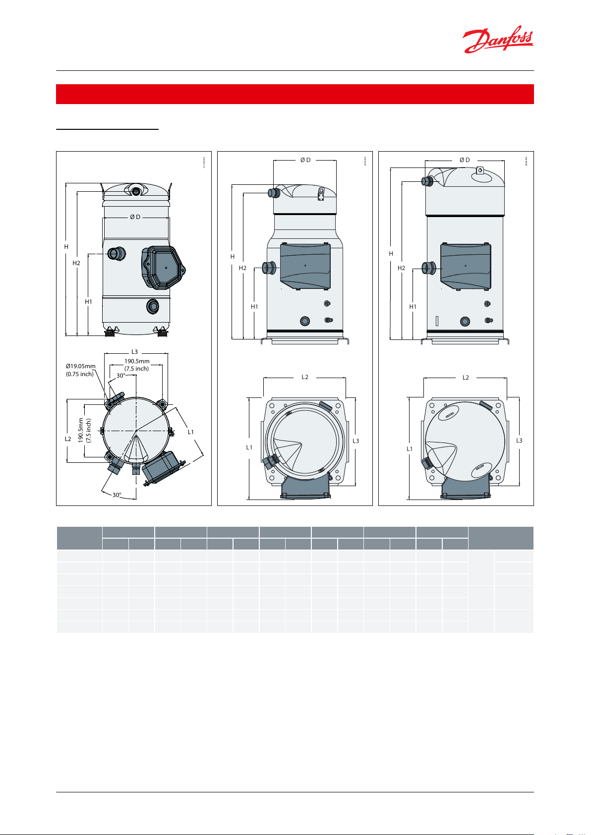
Scroll compressors, DSF090 to DSF530 | Dimensions
Dimensions
Single compressors
Figure 8: Outline drawing number 1
Figure 9: Outline drawing number 2
Figure 10: Outline drawing number 3
Table 11: Single compressor
© Danfoss | Climate Solutions | 2021.10 AB309735209512en-000401 | 18
Page 19
H
L
8556230
D
L1
H1
H
L
L1
H1
D
8556228
D
H
L
L1
H1
8556222
L1
H1
H
L
D
8556223
H1
CC-000056
L1
L
H
D
Tandem mod‐
el
Composition Cp1
+ Cp2
LDHL1H1
Outline drawing
number
mm
inchmminchmminchmminchmminch
DSF180E
DSF090+DSF090
850
33.46
384
15.12
507
19.96
240
9.45
242
9.5318560144
DSF200E
DSF100+DSF100
850
33.46
384
15.12
507
19.96
240
9.45
242
9.5318560144
DSF230E
DSF115+DSF115
850
33.46
384
15.12
565
22.24
240
9.45
242
9.5318560145
DSF260E
DSF130+DSF130
850
33.46
384
15.12
565
22.24
240
9.45
242
9.5318560145
DSF215U
DSF100+DSF115
850
33.46
386
15.20
565
22.24
240
9.45
242
9.5318560189
DSF230U
DSF100+DSF130
850
33.46
386
15.20
565
22.24
240
9.45
242
9.5318560189
DSF255U
DSF100+DSF155
850
33.46
386
15.20
565
22.24
240
9.45
242
9.5318560189
DSF275U
DSF100+DSF175
850
33.46
386
15.20
565
22.24
240
9.45
242
9.5318560189
DSF285U
DSF130+DSF155
850
33.46
386
15.20
565
22.24
240
9.45
242
9.5318560168
DSF300U
DSF100+DSF200
850
33.46
428
16.85
580
22.83
240
9.45
242
9.5318560190
DSF305U
DSF130+DSF175
850
33.46
386
15.20
565
22.24
240
9.45
242
9.5318560168
DSF310E
DSF155+DSF155
850
33.46
384
15.12
565
22.24
240
9.45
242
9.5318560145
DSF315U
DSF115+DSF200
850
33.46
428
16.85
580
22.83
240
9.45
242
9.5318560167
DSF330U
DSF155+DSF175
850
33.46
386
15.20
565
22.24
240
9.45
242
9.5318560168
DSF331U
DSF130+DSF200
850
33.46
428
16.85
580
22.83
240
9.45
242
9.5318560167
DSF350E
DSF175+DSF175
850
33.46
384
15.12
565
22.24
240
9.45
242
9.5318560145
DSF355U
DSF155+DSF200
850
33.46
428
16.85
580
22.83
240
9.45
242
9.5318560167
DSF375U
DSF175+DSF200
850
33.46
428
16.85
580
22.83
240
9.45
242
9.5318560167
DSF400E
DSF200+DSF200
850
33.46
428
16.85
580
22.83
240
9.45
242
9.5318560146
DSF400X
DSF130+DSF270
903
35.55
533
20.98
731
28.78
359
14.13
211
8.3158560169
DSF470X
DSF200+DSF270
903
35.55
533
20.98
731
28.78
359
14.13
211
8.3158560170
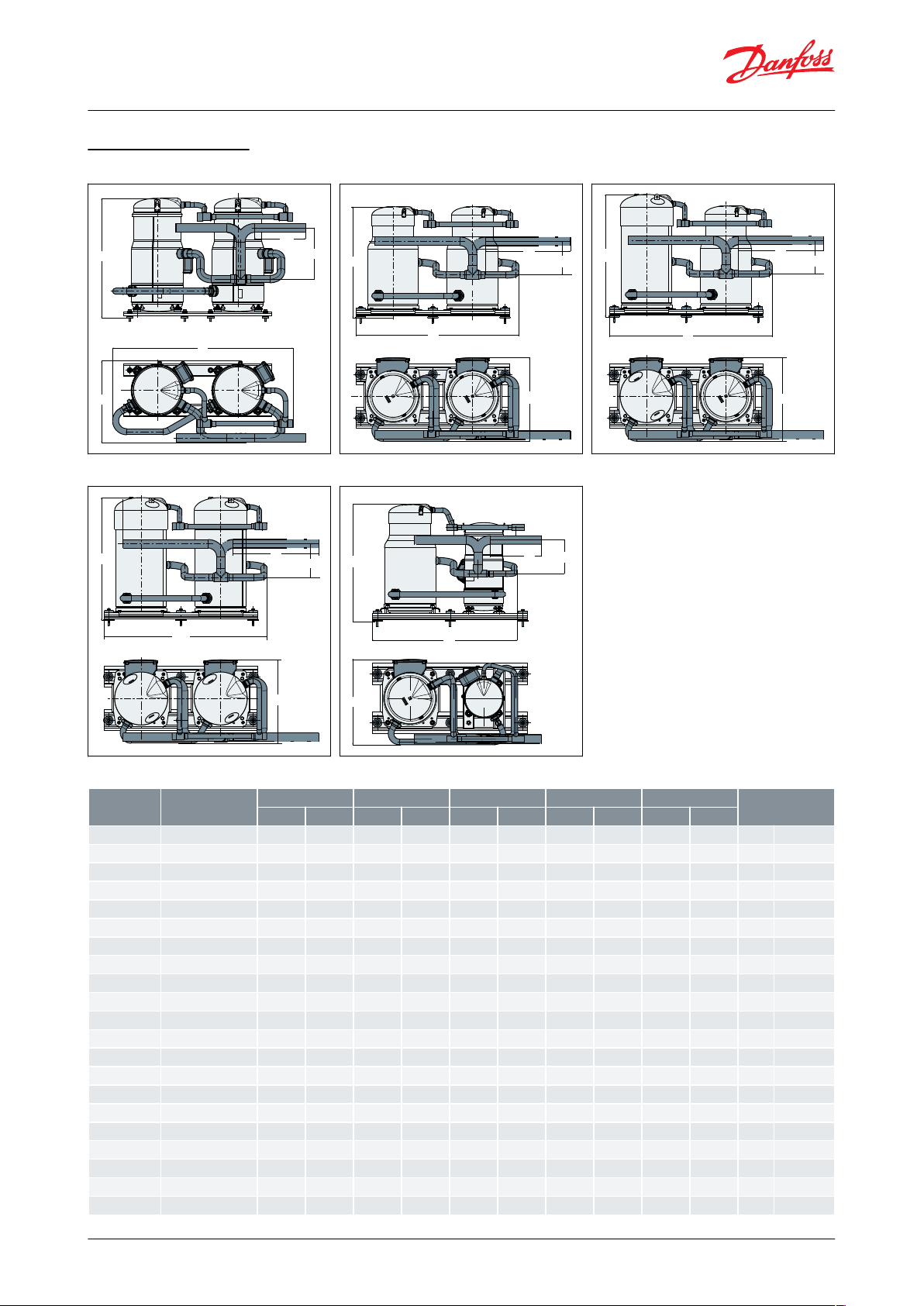
Scroll compressors, DSF090 to DSF530 | Dimensions
Tandem assemblies
Figure 11: Outline drawing number 1
Figure 14: Outline drawing number 4
Figure 12: Outline drawing number 2
Figure 15: Outline drawing number 5
Figure 13: Outline drawing number 3
Table 12: Tandem assemblies
© Danfoss | Climate Solutions | 2021.10 AB309735209512en-000401 | 19
Page 20
CC-000057
H
D
H1
L1
L
CC-000058
H
D
H1
L1
L
H1
L1
H
L
8556217
L
H1
L1
H
8556216
Tandem mod‐
el
Composition Cp1
+ Cp2
LDHL1H1
Outline drawing
number
mm
inchmminchmminchmminchmminch
DSF500X
DSF175+DSF325
903
35.55
533
20.98
731
28.78
359
14.13
211
8.3158560169
DSF525X
DSF200+DSF325
903
35.55
533
20.98
731
28.78
359
14.13
211
8.3158560170
DSF540E
DSF270+DSF270
1025
40.35
527
20.75
701
27.6
535
21.06
211
8.3128556228
DSF595U
DSF270+DSF325
1025
40.35
527
20.75
701
27.6
535
21.06
211
8.3128556228
DSF650E
DSF325+DSF325
1025
40.35
527
20.75
701
27.6
535
21.06
211
8.3128556228
DSF800U
DSF270+DSF530
1025
40.35
546
21.5
774
30.5
535
21.06
211
8.3138556207
DSF970E
DSF485+DSF485
1025
40.35
553
21.77
774
30.5
640
25.2
211
8.3148556205
DSF855U
DSF325+DSF530
1025
40.35
546
21.5
774
30.5
640
25.2
211
8.3148556220
DSF1060E
DSF530+DSF530
1025
40.35
553
21.77
774
30.5
640
25.2
211
8.3148556205
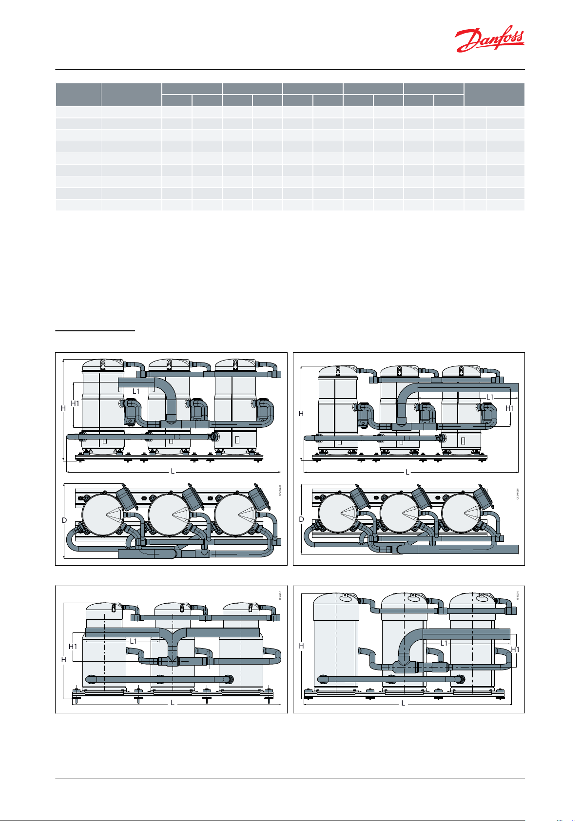
Scroll compressors, DSF090 to DSF530 | Dimensions
NOTE:
Tandems to be achieved by assembly of individual compressors.
By convention, the last letter of tandems designation have been set to help to discern easily which type of manifold
we are considering.
U : Uneven tandem
E : Even tandem
X: Crossplatfom (medium-large) tandem
Trio assemblies
Figure 16: Outline drawing number 6
Figure 18: Outline drawing number 8
Figure 17: Outline drawing number 7
Figure 19: Outline drawing number 9
© Danfoss | Climate Solutions | 2021.10 AB309735209512en-000401 | 20
Page 21

Tandem model
Composition
LDHL1H1
Outline drawing
number
mm
inchmminchmminchmminchmminch
DSF465T
3 x DSF155
1230
48.4
402
15.8
571
22.5
205
8.1
242
9.568560172
1326
52.2
402
15.8
571
22.5
622
24.5
242
9.578560172
DSF525T
3 x DSF175
1230
48.4
402
15.8
571
22.5
205
8.1
242
9.568560172
1326
52.2
402
15.8
571
22.5
622
24.5
242
9.578560172
DSF 600T
3 x DSF200
1236
48.7
433
17.0
587
23.1
205
8.1
242
9.568560171
1326
52.2
433
17.0
587
23.1
622
24.5
242
9.578560171
DSF810T
DSF270+DSF270+DSF270
1467
57.76
543
21.38
701
27.6
535 min
21.06
211
8.3188556217
DSF975T
DSF325+DSF325+DSF325
1467
57.76
543
21.38
701
27.6
536 min
21.06
211
8.3188556217
DSF1180T
DSF325+DSF325+DSF530
1467
57.76
573
22.56
774
30.5
535 min
21.06
211
8.3188556310
DSF1385T
DSF530+DSF530+DSF325
1520
59.84
573
22.56
774
30.5
640 min
25.19
244
9.6198556314
DSF1590T
DSF530+DSF530+DSF530
1520
59.84
573
22.56
774
30.5
640 min
25.19
244
9.6198556216
Scroll compressors, DSF090 to DSF530 | Dimensions
Table 13: Trio assemblies
NOTE:
Trio to be achieved by assembly of individual compressors.
© Danfoss | Climate Solutions | 2021.10 AB309735209512en-000401 | 21
Page 22

CC-000167
CC-000168
Connection Details
DSF090-100
DSF115-200
DSF270-325
DSF485-530
Suction connection
Brazed 1"1/8
Brazed 1"3/8
Brazed 1"5/8
Brazed 1"5/8
Discharge connection
Brazed 7/8"
Brazed 7/8"
Brazed 1"1/8
Brazed 1"3/8
Oil sight glass
Threaded (1"1/8 – 18 UNEF)
Oil equalization connection
Rotolock 1"3/4
Rotolock 2"1/4
Oil drain connection
None
None
Female ¼" Flare incorporating a Schrader valve
Low pressure gauge port (Shrader)
Male ¼" Flare incorporating a Schrader valve
Outline drawing
112
2
Scroll compressors, DSF090 to DSF530 | Mechanical connections
Mechanical connections
Connection details
Table 14: Connection details
Figure 20: Outline drawing 1
Figure 21: Outline drawing 2
Design compressor mounting
General requirements
Compressors used in single applications must be mounted with exible grommets.
Compressors used in parallel applications must be mounted with rigid spacers onto rails (or directly on rails
according to compressor models) and the manifold assembly must be mounted with exible grommets onto the
frame.
During operation, the maximum inclination from the vertical plane must not exceed 3 degrees.
Single requirements DSF090-200 mounting
Compressors DSF090-200 are delivered with rubber grommets and steel mounting sleeve used to isolated the
compressor from the base frame.
© Danfoss | Climate Solutions | 2021.10 AB309735209512en-000401 | 22
Page 23

15 mm
(0.59 Inch)
1
2
3
4
5
6
7
cc-0048
1234567
Tightening torque 15 Nm
HM 8 bolt (4 pcs)
Lock washer (4 pcs)
Flat washer (4 pcs)
Steel mounting sleeve (4 pcs)
Rubber grommet (4 pcs)
Nut (4 pcs)
1
CC-0000001
27.5 mm
(1.08 inch)
CC-0049
2
8
3
4
5
6
7
1234567
8
Rubber grommets from kit 8156138
HM 8 bolt
Lock washer
Flat washer
Steel mounting sleeve
Rubber grommet
Nut
Compressor base plate
Scroll compressors, DSF090 to DSF530 | Mechanical connections
The grommets must be compressed until contact between the at washer and the steel mounting sleeve is
established. The required bolt size for the DSF090-200 compressors is HM8-40. This bolt must be tightened to a
torque of 15Nm.
Figure 22: Rubber grommets
Part 2, 3, 4, 5, 6 and 7 are delivered along with
compressor
Single requirements, DSF270-325-485-530 mounting
To be used in single applications, an additional accessory including exible grommets is necessary kit 8156138.
The grommets must be compressed until contact between the at washer and the steel mounting sleeve is
established. The required bolt size for the DSF compressors is HM8-55. This bolt must be tightened to a torque of 21
Nm.
Figure 23: Rubber grommets from kit 8156138
Figure 24: Rubber grommets
Manifolding requirements DSF 180E-400E and DSF285U-305U-330U mounting
The compressors must be mounted with rigid mounting spacers on rails. Rubber grommets and spacers must be
installed below the rails.
The rigid mounting spacers are included in tandem accessory kits. The rubber grommets are supplied with
compressor.
For more details about parallel mounting feet, please see parallel unit outline drawing.
© Danfoss | Climate Solutions | 2021.10 AB309735209512en-000401 | 23
Page 24

2
3
4
1
CC-000002
1234Tightening torque 15Nm
Not supplied Φ8x75mm 0.31x2.95inch
Tightening torque 15Nm
4mm (0.16 inch) thickness
Supplied with the compressor
Included in manifolding kit
Not supplied
1
2
3
4
5
CC-000003
4
3
2
1
CC-000004
12345
Tightening torque 15Nm
Not supplied HM8mm 0.31 inch
Tightening torque 15 Nm
4mm (0.16 inch) Thickness
Additional rigid spacer (Refer to table below)
Supplied with the compressor
Included in manifolding kit
Not supplied
Scroll compressors, DSF090 to DSF530 | Mechanical connections
Figure 25: DSF 180E-400E and DSF285U-305U-330U mounting
Manifolding requirements DSF 215U-230U-255U-275U-300U-315U-331U-355U-375U mounting
The compressors must be mounted with rigid mounting spacers on rails. Rubber grommets and spacers must be
installed below the rails.
The rigid mounting spacers are included in tandem accessory kits. The rubber grommets are supplied with
compressor.
Figure 26: Smaller model of tandem
Figure 27: Larger model of tandem
© Danfoss | Climate Solutions | 2021.10 AB309735209512en-000401 | 24
Page 25

1
2
3
4
CC-000009
1234Tightening torque 15Nm
Not supplied HM8mm 0.31 inch
Tightening torque 15 Nm
3mm (0.12inch) Thickness
Supplied with the compressor
Included in manifolding kit
Not supplied
1
CC-000010
4
5
2
3
7
6
5
CC-000011
Additionnal rigid spacer
Additional right spacer(to be added on the smallest compressor of the tan‐
dem)
DSF215U-230U-255U-275U-315U-331U-355U-375U
7mm
DSF300U
14mm
Scroll compressors, DSF090 to DSF530 | Mechanical connections
Table 15: Additionnal rigid spacer
Tandem requirements DSF465T-525T-600T mounting
The compressors must be mounted with rigid mounting spacers on rails. Rubber grommets and spacers must be
installed below the rails.
The rigid mounting spacers and rubber grommets are included in tandem accessory kits.
Tandem requirements DSF400X-470X-500X-525X mounting
The large compressor, DSF270,325, is mounted with rigid spacers on the rails.
The DSF130, 175,200 compressor is xed on beams by rigid spacer, and the beams are mounted with rigid spacers
on the rails. Rubber grommets and spacers must be installed below the rails.
Figure 28: DSF270-325
Figure 29: DSF130-175-200
© Danfoss | Climate Solutions | 2021.10 AB309735209512en-000401 | 25
Page 26

2
1
3
CC-000012
123
HM 10 x 30 class 10.9, Tightening torque 50 Nm
HM 10 x 100 class 10.9, Tightening torque 50
Nm
Thickness: 5 mm (0.2 inch)
Included in tandem/trio kit
Not supplied
1234567
Tightening torque 16Nm
Not supplied Φ10mm
Tightening torque 50Nm
Tightening torque 55Nm
5mm (0.2inch) thickness
Tightening torque 15Nm
4mm (0.16inch) thickness
Supplied with the compressor
Included in manifolding kit
Not supplied
Scroll compressors, DSF090 to DSF530 | Mechanical connections
Tandem requirements, DSF540E to DSF1590T mounting
For parallel mounting, the compressors can be mounted directly on the rails. Rubber grommets and spacers must be
installed below the rails.
These parts are included in accessories.
Figure 30: DSF540E to DSF1590T mounting
Design piping
General requirements
Proper piping practices should be employed to:
1.
Ensure adequate oil return, even under minimum load conditions (refrigerant speed, piping slopes…). For
validation tests see section Manage oil in the circuit.
2.
Avoid condensed liquid refrigerant from draining back to the compressor when stopped (discharge piping
upper loop). For validation tests see section Manage o cycle migration.
3.
Piping should be designed with adequate three-dimensional exibility to avoid excess vibration. It should not be
in contact with the surrounding structure, unless a proper tubing mount has been installed. For more
information on noise and vibration, see section Sound and vibration data.
© Danfoss | Climate Solutions | 2021.10 AB309735209512en-000401 | 26
Page 27

HP
3
3
2
2
5
4 m*
4 m*
6
6
6
1
LP
4
CC-0043
123456*
Evaporator
0.5% slope
4m/s or more
8 to 12 m/s
To condenser
U-trap, as short as possible
Max.
CC-000162
HP
LP
3
1
2
123
3D exibility
Upper loop
Condenser
Scroll compressors, DSF090 to DSF530 | Mechanical connections
Figure 31: Proper piping - Evaporator
Figure 32: Proper piping - Condenser
Tandem and Trio requirements (Static)
DSF tandem and trio use static oil balancing principle to equalize oil level between the compressors by gravity. This
is ensured by a precise suction and oil equalization piping design.
The discharge line has no impact on oil balancing. It is shown with tee, to indicate that both left and right side
discharge headers are possible.
By default, DSF tandems and trios are not factory-built.
To complete an assembly in the eld, you will need:
• Tubings, according to specic outline drawings indicated in the following table
• Manifolding accessory kit
• Compressors
© Danfoss | Climate Solutions | 2021.10 AB309735209512en-000401 | 27
Page 28

CC-000037
Included in tandem or trio accessory kit
Not supplied
Cp3
Cp2
Cp1
CC-000035
1
Cp3
Cp2
Cp1
2
CC-000036
12Cp1
Cp2
Cp3
Trio models with Right suction
Trio models with Left suction
Compressor 1
Compressor 2
Compressor 3
Tandem
model
Composition
Suction
Discharge
Oil equali‐
zation
Outline
drawing
number
Suction
from
Washer inner diameter
Washer in
suction of
Tandem kit
code no
DSF180E
DSF090+DSF090
1"5/8
1"3/8
1"1/8
8560144
Left
Not needed
120Z0634
Right
DSF200E
DSF100+DSF100
1"5/8
1"3/8
1"1/8
8560144
Left
Not needed
120Z0634
Right
DSF215U
DSF100+DSF115
1"5/8
1"3/8
1"1/8
8560189
Left
25 mm (0.98 inch)
Cp2
120Z0694
Right
26 mm (1.02 inch)
Cp2
Scroll compressors, DSF090 to DSF530 | Mechanical connections
Suction and oil equalization piping drawings must be respected (diameters, minimum straight lengths, …).
Suction washer position
Depending on manifold conguration, it is essential to equalize the pressure of compressor sumps. Hence, a
suction washer must be added on certain compressors according to the table. Suction washers are included in
tandem or trio accessory kits as described in the illustrations.
Figure 33: Suction washer position
By convention, the compressor order (No.1, No.2 ...) is dened counting from left to right, placed on the side facing
the electrical boxes of the compressors (see example below on a trio)
Figure 34: Example of right suction
Figure 35: Example of left suction
Tandem models
Table 16: Tandem models
© Danfoss | Climate Solutions | 2021.10 AB309735209512en-000401 | 28
Page 29

Tandem
model
Composition
Suction
Discharge
Oil equali‐
zation
Outline
drawing
number
Suction
from
Washer inner diameter
Washer in
suction of
Tandem kit
code no
DSF230E
DSF115+DSF115
1"5/8
1"3/8
1"1/8
8560145
Left
Not needed
120Z0634
Right
DSF230U
DSF100+DSF130
1"5/8
1"3/8
1"1/8
8560189
Left
27mm (1.06 inch)
Cp2
120Z0694
Right
27mm (1.06 inch)
Cp2
DSF255U
DSF100+DSF155
1"5/8
1"3/8
1"1/8
8560189
Left
23 mm (0.91 inch)
Cp1
120Z0694
Right
23 mm (0.91 inch)
Cp1
DSF260E
DSF130+DSF130
1"5/8
1"3/8
1"1/8
8560145
Left
Not needed
120Z0634
Right
DSF275U
DSF100+DSF175
1"5/8
1"3/8
1"1/8
8560189
Left
21 mm (0.83 inch)
Cp1
120Z0694
Right
21 mm (0.83 inch)
Cp1
DSF285U
DSF130+DSF155
1"5/8
1"3/8
1"1/8
8560168
Left
27 mm (1.06 inch)
Cp1
120Z0692
Right
27 mm (1.06 inch)
Cp1
DSF300U
DSF100+DSF200
1"5/8
1"3/8
1"1/8
8560190
Left
20 mm (0.79 inch)
Cp1
120Z0693
Right
20 mm (0.79 inch)
Cp1
DSF305U
DSF130+DSF175
1"5/8
1"3/8
1"1/8
8560168
Left
25 mm (0.98 inch)
Cp1
120Z0692
Right
25 mm (0.98 inch)
Cp1
DSF310E
DSF155+DSF155
1"5/8
1"3/8
1"1/8
8560145
Left
Not needed
120Z0634
Right
DSF315U
DSF115+DSF200
1"5/8
1"3/8
1"1/8
8560167
Left
23 mm (0.91 inch)
Cp1
120Z0693
Right
23 mm (0.91 inch)
Cp1
DSF330U
DSF155+DSF175
1"5/8
1"3/8
1"1/8
8560168
Left
27.5 mm (1.08 inch)
Cp1
120Z0692
Right
26 mm (1.02 inch)
Cp1
DSF331U
DSF130+DSF200
1"5/8
1"3/8
1"1/8
8560167
Left
24 mm (0.94 inch)
Cp1
120Z0694
Right
24 mm (0.94 inch)
Cp1
DSF350E
DSF175+DSF175
1"5/8
1"3/8
1"1/8
8560145
Left
Not needed
120Z0634
Right
DSF355U
DSF155+DSF200
1"5/8
1"3/8
1"1/8
8560167
Left
25 mm (0.98 inch)
Cp1
120Z0694
Right
25 mm (0.98 inch)
Cp1
DSF375U
DSF175+DSF200
1"5/8
1"3/8
1"1/8
8560167
Left
27.5 mm (1.08 inch)
Cp1
120Z0694
Right
27.5 mm (1.08 inch)
Cp1
DSF400E
DSF200+DSF200
1"5/8
1"3/8
1"1/8
8560146
Left
Not needed
120Z0634
Right
DSF400X
DSF130+DSF270
2"1/8
1"3/8
1"3/8
8560169
Left
24 mm (0.94 inch)
Cp1
120Z0709
Right
25 mm (0.98 inch)
Cp1
DSF470X
DSF200+DSF270
2"1/8
1"3/8
1"3/8
8560170
Left
35.5 mm (1.4 inch)
CP2
120Z0709
Right
35.5 mm (1.4 inch)
CP2
DSF500X
DSF175+DSF325
2"1/8
1"3/8
1"3/8
8560169
Left
25 mm (0.98 inch)
Cp1
120Z0709
Right
26 mm (1.02 inch)
Cp1
DSF525X
DSF200+DSF325
2"1/8
1"3/8
1"3/8
8560170
Left
26 mm (1.02 inch)
Cp1
120Z0709
Right
26 mm (1.02 inch)
Cp1
DSF540E
DSF270+DSF270
2"1/8
1" 5/8
1" 3/8
8556228
Left
Not needed
120Z0792
Right
DSF595U
DSF270+DSF325
2"1/8
1" 5/8
1" 3/8
8556228
Left
31 mm (1.22 inch)
Cp1
120Z0796
Right
DSF650E
DSF325+DSF325
2"1/8
1" 5/8
1" 3/8
8556228
Left
Not needed
120Z0792
Right
DSF800U
DSF270+DSF530
2"1/8
1" 5/8
1" 5/8
8556207
Left
24 mm (0.94 inch)
Cp1
120Z0786
Right
DSF970E
DSF485+DSF485
2"5/8
1" 5/8
1" 5/8
8556205
Left
Not needed
120Z0785
Right
DSF855U
DSF325+DSF530
2"5/8
1" 5/8
1" 5/8
8556220
Left
27 mm (1.06 inch)
Cp1
120Z0787
Right
DSF1060E
DSF530+DSF530
2"5/8
1" 5/8
1" 5/8
8556205
Left
Not needed
120Z0785
Right
Scroll compressors, DSF090 to DSF530 | Mechanical connections
© Danfoss | Climate Solutions | 2021.10 AB309735209512en-000401 | 29
Page 30

1 2
CC-000034
12Organ pipe
Tightening torque 100Nm
Supplied with the compressor
Included in tandem kit
Trio model
Composition
Suction
Discharge
Oil equali‐
zation
Outline
drawing
number
Suction
from
Washer inner diameter
Washer in
suction of
Trio kit
code no
DSF465T
3xDSF155
2"1/8
1"3/8
1"1/8
8560172
Left
26 mm (1.02 inch)
CP1
120Z0714
25 mm (0.98 inch)
CP3
Right
26 mm (1.02 inch)
CP1
24 mm (0.94 inch)
CP3
DSF525T
3xDSF175
2"1/8
1"3/8
1"1/8
8560172
Left
26 mm (1.02 inch)
CP1
120Z0714
25 mm (0.98 inch)
CP3
Right
26 mm (1.02 inch)
CP1
25 mm (0.98 inch)
CP3
DSF600T
3xDSF200
2"1/8
1"3/8
1"1/8
8560171
Left
26 mm (1.02 inch)
CP1
120Z0714
25 mm (0.98 inch)
CP3
Right
25.5 mm (1.00 inch)
CP1
25 mm (0.98 inch)
CP3
DSF810T
DSF270+DSF270 +DSF270
2"5/8
1" 5/8
1" 5/8
8556217
Left
30 mm (1.18 inch)
Cp3
120Z0784
Right
34.5 mm (1.36 inch)
Cp1 & Cp3
120Z0794
DSF975T
DSF325+DSF325 +DSF325
2"5/8
1" 5/8
1" 5/8
8556217
Left
30 mm (1.18 inch)
Cp3
120Z0784
Right
34.5 mm (1.36 inch)
Cp1 & Cp3
120Z0794
DSF1180T
DSF325+DSF325+DSF530
2"5/8
1" 5/8
1" 5/8
8556310
Left--
120Z0790
Right
29 mm (1.14)
Cp1 & Cp2
120Z0815
DSF1385T
DSF530+DSF530+DSF325
3"1/8
1" 5/8
1" 5/8
8556314
Left
26 mm (1.02)
Cp3
120Z0814
Right
26 mm (1.02)
Cp1
120Z0815
DSF1590T
DSF530+DSF530 +DSF530
3"1/8
2" 1/8
1" 5/8
8556216
Left
33 mm (1.3 inch)
Cp2 & Cp3
120Z0793
Right
Scroll compressors, DSF090 to DSF530 | Mechanical connections
Trio models
Table 17: Trio models
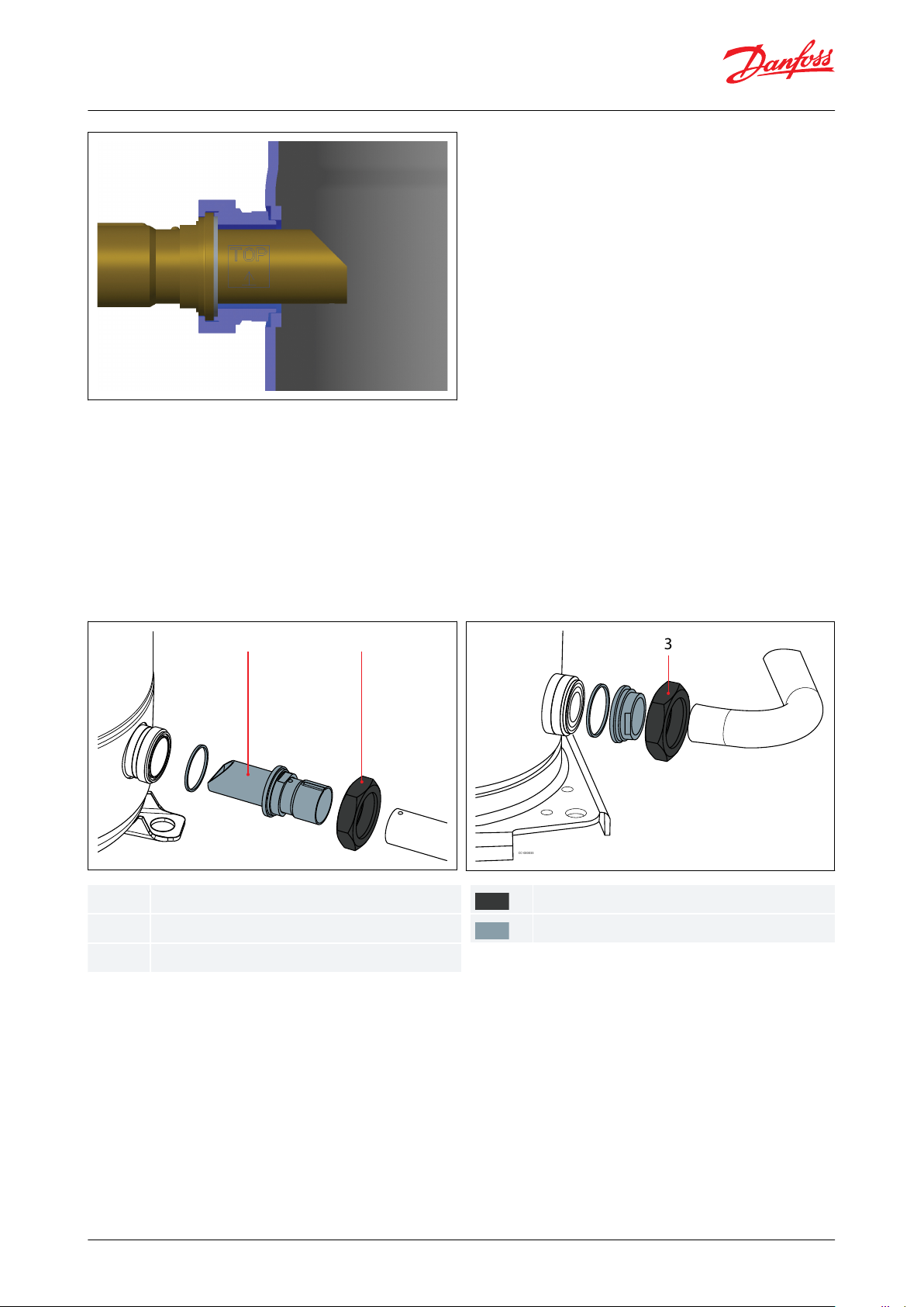
Oil equalization DSF180E-400E
The oil level is balanced by a pipe of 1"1/8 oil equalization line.
In order ensure best oil balance, the organ pipe need to be mounted inside the oil equalization port as indicated on
below picture. To connect the equalization line on rotolock connections, the organ pipe adaptor and teon gasket
are included in the tandem kit must be used.
The organ pipe needs to be installed in the direction indicated by the label attached on pipe surface, which will
ensure best oil balance.
© Danfoss | Climate Solutions | 2021.10 AB309735209512en-000401 | 30
Page 31
1 2
CC-000032
3
CC-000033
123
Organ pipe
Tightening torque 100Nm
Tightening torque 145Nm
Supplied with the compressor
Included in tandem kit
Scroll compressors, DSF090 to DSF530 | Mechanical connections
Oil equalization design DSF 400X-470X-500X-525X
The oil level is balanced by a pipe of 1"3/8 oil equalization line.
In order to ensure best oil balance, the organ pipe need to be mounted inside the DSF130, DSF175, DSF200 oil
equalization port as indicated on below picture. DSF270, DSF325 has integrated organ pipe inside the oil
equalization port.
To connect the equalization line on rotolock connections, the organ pipe, adaptor sleeves, Teon gaskets included
in the tandem accessory kit must be used.
Figure 36: For DSF130, DSF175, DSF200
Figure 37: For DSF270, DSF325
Oil equalization design DSF270-530
The oil level is balanced by a pipe of 1"3/8 or 1"5/8. To connect the equalization line on rotolock connections, the
adaptor sleeves included in the tandem or trio accessory kit must be used.
© Danfoss | Climate Solutions | 2021.10 AB309735209512en-000401 | 31
Page 32

3
CC-000033
3
Tightening torque 145 Nm
Supplied with the compressor
Included in tandem kit
Scroll compressors, DSF090 to DSF530 | Mechanical connections
Figure 38: DSF270, DSF530
© Danfoss | Climate Solutions | 2021.10 AB309735209512en-000401 | 32
Page 33

4
1
2
3
CC-0031
1234Terminal box
Ø 29mm (φ1.14inch) knockout
Ø 25.5mm (φ1inch) knockout
Power supply
3
2
1
CC-0400
123
Ø 16.5mm (φ0.65inch) knockout
Ø 40.5mm (φ1.59inch) hole
Power supply
Scroll compressors, DSF090 to DSF530 | Electrical connections
Electrical connections
Wiring connections
According to compressor model, electrical power is connected to the compressor terminals either by 4.8mm (10-32)
screws or by M5 studs and nuts. In both cases the maximum tightening torque is 3 Nm.
Cable gland or similar protection component must be used on electrical box's knockouts to against accidental
contact with electrical parts inside.
DSF090-175
The terminal box is provided with a Ø 25.5mm (φ1 inch) (ISO25) and a Ø 29mm (φ1.14) (PG21) knockouts.
Figure 39: Wiring connections for DSF090-175
DSF200
The terminal box is provided with a Ø 40.5mm (φ1.59inch) hole (ISO40) for power supply and a Ø 16.5mm
(φ0.65inch) knockout (ISO16).
Figure 40: Wiring connections for DSF200
DSF270-325-485-530
The terminal box is provided with 2 triple knockouts and 1 single knockout for power supply and 4 double
knockouts for the safety control circuit.
The 3 power supply knockouts accommodate the following diameters:
© Danfoss | Climate Solutions | 2021.10 AB309735209512en-000401 | 33
Page 34

2
3
1
8
6
7
4
3
2
1
5
L1
L N S1 S2 M1M2
L2 L3
CC-0517
12345678Black
Blue
Brown
M1, M2 Control circuit
Module power supply
Sump heater
Faston 1/4" tabs
Power supply
L N S1 S2 M1 M2
L1 L2 L3
2
3
4
5
1
CC-0035
L1L2L312345Black
Blue
Brown
Phase sequence input
Internal control contact
Safety circuit
Thermistor connection
Module power
Motor voltage code
Code 4
50 Hz
Nominal voltage
400 V - 3ph
50 Hz
Voltage range
360-440V
60 Hz
Nominal voltage
460V-3ph
60 Hz
Voltage range
414-506V
Scroll compressors, DSF090 to DSF530 | Electrical connections
• Ø 50.8 mm (φ 2 inch) (UL 1"1/2 conduit) & Ø 43.7 mm (φ 1.72 inch) (UL 1"1/4 conduit) & Ø 34.5 mm (φ 1.36 inch)
(UL 1" conduit)
• Ø 40.5 mm (φ 1.59 inch) (ISO40) & Ø 32.2 mm (φ 1.27 inch) (ISO32) & Ø 25.5 mm (φ 1 inch) (ISO25)
• Ø 25.5 mm (φ 1 inch) (ISO25)
The 4 others knockouts are as follows:
• Ø 22.5 mm (φ 0.89 inch) (PG16) (UL 1/2") & Ø 16.5 mm (φ 0.65 inch) (ISO16) (x2)
• Ø 20.7 mm (φ 0.81 inch) (ISO20 or PG13.5) (x2)
Figure 41: Wiring connections for DSF270-325-485-530
Motor protection module
The motor protection modules come preinstalled within the terminal box. Phase sequence protection connections
and thermistor connections are pre-wired and should not be removed.
The module must be connected to a power supply of the appropriate voltage. The module terminals are 6.3 mm
(0.25 inch) size Faston type.
Figure 42: Motor protection module
Electrical specications
Motor voltage
Danfoss scroll compressors DSF are available in motor voltage listed below.
Table 18: Motor voltage
© Danfoss | Climate Solutions | 2021.10 AB309735209512en-000401 | 34
Page 35

Vavg
V1-2
V1-3
V2-3
Mean voltage of phases 1, 2, 3.
Voltage between phases 1 and 2.
Voltage between phases 1 and 3.
Voltage between phases 2 and 3.
Compressor models
LRA
Max. operating current
Winding resistance
AAΩ
DSF0909817
1.47
DSF1009819
1.47
DSF115
142221.05
DSF130
142241.05
DSF155
147270.92
DSF175
158300.83
DSF200
197340.83
DSF270
191440.62
DSF325
231540.52
DSF485
343830.28
DSF530
343920.28
Scroll compressors, DSF090 to DSF530 | Electrical connections
NOTE:
Voltage range: Nominal voltage ± 10%. The voltage range indicates where the compressor can run in the majority
of the application envelope. A boundary voltage supply which accumulates under specic conditions such as high
ambiance, high superheat, or map boundary conditions, may lead to a compressor trip.
Voltage imbalance
The maximum allowable voltage imbalance is 2%. Voltage imbalance causes high amperage over one or several
phases, which in turn leads to overheating and possible motor damage. Voltage imbalance is given by the formula:
% voltageimbalance =
| Vavg − V1−2 | + | Vavg − V1−3 | + | Vavg − V2−3 |
2×Vavg
×100
IP rating
The compressor terminal box according to IEC60529 is IP54 for all models when correctly sized IP54 rated cable
glands are used.
First numeral, level of protection against contact and foreign objects
5 - Dust protected
Second numeral, level of protection against water
4 - Protection against water splashing
Terminal box temperature
The temperature inside the terminal box must not exceed 70 °C (158 °F). Consequently, if the compressor is
installed in an enclosure, precautions must be taken to avoid that the temperature around the compressor and in
the terminal box would rise too much. A ventilation installation on the enclosure panels may be necessary. If not,
the electronic protection module may not operate properly. Any compressor damage related to this will not be
covered by Danfoss warranty. In the same manner, cables must be selected in a way that ensures the terminal box
temperature does not exceed 70 °C (158 °F).
Three phase electrical characteristics
Table 19: Motor voltage code 4 - 400V/3ph/50Hz, 460V/3ph/60Hz
© Danfoss | Climate Solutions | 2021.10 AB309735209512en-000401 | 35
Page 36

t
25°CtambR25°C (77°F)
R
amb
a
reference temperature = 25°C (77°F)
temperature during measurement °C (°F)
winding resistance at 25°C (77°F)
winding resistance at tamb
Coecient a = 234.5
Scroll compressors, DSF090 to DSF530 | Electrical connections
LRA (Locked Rotor Amp)
Locked Rotor Amp value is the higher average current as measured on mechanically blocked compressors tested
under nominal voltage. The LRA value can be used as a rough estimation for the starting current. However, in most
cases, the real starting current will be lower. A soft starter can be applied to reduce starting current (see section Soft
starts).
MOC (Maximum Operating Current)
The max operating current is the amperage the compressor will draw when it operates at maximum load of
operating envelope within the voltages printed on the nameplate.
MOC can be used as a basis for contactors selection.
Winding resistance
Winding resistance is the resistance between phases at 25°C (77°F) (resistance value +/- 7%). Winding resistance is
generally low and it requires adapted tools for precise measurement. Use a digital ohm-meter, a “4 wires” method
and measure under stabilised ambient temperature. Winding resistance varies strongly with winding temperature. If
the compressor is stabilised at a dierent value than 25°C (77°F), the measured resistance must be corrected using
the following formula:
R
tamb
= R
25°C(77°F)
a + t
a + t
amb
25°C(77°F)
Motor protection
DSF090 to DSF200
Compressor models DSF090 to 200 are provided with internal overload motor protection to prevent against
excessive current and temperature caused by overloading, low refrigerant ow or phase loss.
The protector is located in star point of motor and, should it be activated, will cut out all three phases. It will be reset
automatically.
While not compulsory, an additional thermal magnetic motor circuit breaker is still advisable for either alarm or
manual reset.
Then it must be set at max operating current:
• When the motor temperature is too high, then the internal protector will trip.
• When the current is too high the thermal magnetic motor circuit breaker will trip before the internal protection
therefore oering possibility of manual reset.
DSF270 to DSF530
DSF compressors are delivered with a pre-installed motor protection module inside the terminal box. This device
provides ecient and reliable protection against overheating and overloading as well as phase loss/reversal.
The motor protector comprises a control module and PTC sensors embedded in the motor winding.
© Danfoss | Climate Solutions | 2021.10 AB309735209512en-000401 | 36
Page 37

*
460 ms
1s*
40 ms 460 ms40 ms
approx. 1 second
*
1s*
80 ms 920 ms
approx. 1 second
Scroll compressors, DSF090 to DSF530 | Electrical connections
The motor temperature is being constantly measured by a PTC thermistor loop connected on S1-S2 . If any
thermistor exceeds its response temperature, its resistance increases above the trip level (4.500 Ω) and the output
relay then trips – i.e. contacts M1-M2 are open. After cooling to below the response temperature (resistance < 2.750
Ω), a 5-minute time delay is activated.
After this delay has elapsed, the relay is once again pulled in – i.e. contacts M1-M2 are closed. The time delay may be
cancelled by means of resetting the mains (L-N -disconnect) for approximately 5 sec.
A red/green twin LED is visible on the module. A solid green LED denotes a fault free condition. A blinking red LED
indicates an identiable fault condition:
Figure 43: PTC Overheat
Figure 44: Delay timer active (after PTC over temp.)
While not compulsory, an additional thermal magnetic motor circuit breaker is still advisable for either alarm or
manual reset.
Then it must be set below max operating current:
• When the motor temperature is too high, then the internal PTC over temp. and module is activated.
• When the current is too high the thermal magnetic motor circuit breaker will trip before the module activate
therefore oering possibility of manual reset.
Phase sequence and reverse rotation protection
Use a phase meter to establish the phase orders and connect line phases L1, L2 and L3 to terminals T1, T2 and T3,
respectively.
DSF090 to DSF200
Compressor models DSF090 to 200 incorporates an internal reverse vent valve which will react when the
compressor is run in reverse and will allow refrigerant to circulate through a by-pass from the suction to the
discharge. Although reverse rotation is not destructive for these models, it should be corrected as soon as possible.
Repeated reverse rotation over 24 hours may have negative impact on the bearings.
Reverse rotation will be obvious to the user as soon as power is turned on: the compressor will not build up
pressure, the sound level will be abnormally high and power consumption will be minimal. If reverse rotation
symptoms occur, shut the compressor down and connect the phases to their proper terminals. If reverse rotation is
not halted, the compressor will cycle o-on the motor protection.
DSF270 to DSF530
Use a phase meter to establish the phase orders and connect line phases L1, L2 and L3 to terminals T1, T2 and T3,
respectively.
Compressor models DSF270 to 530 are delivered with an electronic module which provides protection against
phase reversal and phase loss at start-up.
The phase sequencing and phase loss monitoring functions are active during a 5-sec window 1 second after
compressor start-up (power on L1-L2-L3).
© Danfoss | Climate Solutions | 2021.10 AB309735209512en-000401 | 37
Page 38

Cp
Ph
0 1s 6s
St
CpPhSt
Compressor
Phase monitoring
start
*
760 ms*
120 ms 400 ms120 ms 120 ms
Approximate
*
1 s*
500 ms 500 ms
Approximate
Scroll compressors, DSF090 to DSF530 | Electrical connections
Figure 45: Phase sequence module logic
Should one of these parameters be incorrect, the relay would lock out (contact M1-M2 open). The red LED on the
module will show the following blink code:
Figure 46: In case of phase reverse error
Figure 47: In case of phase loss error
The lockout may be cancelled by resetting the power mains (disconnect L-N) for approximately 5 seconds.
For more detailed information see “Instructions for electronic module” AN160986418236.
© Danfoss | Climate Solutions | 2021.10 AB309735209512en-000401 | 38
Page 39

1.
2.
3.
1.
2.
3.
1.
2.
Split type
Single compressor
Manifold compressors
Non split
Test No.1
Test No.1+2
Split
Test No.1+3
Test No.1+2+3
Test No.
Purpose
Test conditions
Pass criteria
Solutions
1
Check proper oil
return
A
Lowest foreseeable evaporation, and highest foreseeable condensation.
Minimum number of compressor running for 6 hours.
For reversible system, perform test in both heating and
cooling mode.
Oil level must be visible or full in the
sight glass when the compressor is
running and when all compressors of
the circuit are stopped.
Top-up with oil, generally 3% of
the total system refrigerant
charge (in weight). Above 3%
look for potential oil trap in the
system.
Integrate a function in control
logic to run all compressors simultaneously in order to boost
oil return (for more details see
section Control logic).
Oil separator can be added
2
Check oil balancing
A
Lowest foreseeable evaporation and highest foreseeable
condensation and nominal capacity condition
For tandem 2 compressors running for 6 hours, for trio,
compressor running follow the running sequence:
(1+2+3)2hrs→ (1+2)2hrs →(2+3)2hrs→(1+3)2hrs
For reversible system, perform test in both heating and
cooling mode.
Oil level must be visible or full in the
sight glass when the compressors
are running and when all compressors of the circuit are stopped
Top-up with oil, generally 3% of
the total system refrigerant
charge (in weight).
Check that manifold piping is
conform to Danfoss requirements.
Integrate a function in control
logic to stop manifold periodically in order to balance oil (for
more details see section Control
logic).
3
Oil return in split
systems
Since each installation is unique, test 1 and 2 can not
fully validate the oil return. Oil level must be checked
and adjusted at commissioning.
Oil level must be visible or full in the
sight glass when the compressor is
running and when all compressors of
the circuit are stopped.
Pay special attention to “Piping
design”
Oil separator is strongly recommended, especially in case of
part load.
Scroll compressors, DSF090 to DSF530 | Application
Application
Manage oil in the circuit
Requirement
Oil level must be visible or full in the sight glass when the compressor is running and when all compressors of
the circuit are stopped. For DSF155-200 trio models, top-up oil quantity 1L at least as mandatory.
System evaluation
Table 20: System evaluation
Test, criteria and solutions
Table 21: Test, criteria and solutions
Manage sound and vibration
Sound radiations
We can consider two means to reduce compressors sound radiations:
1.
Acoustic hoods are quick and easy to install and do not increase the overall size of the compressors. Acoustic
hoods are available from Danfoss as accessories. Refer to the tables above for sound levels, attenuation and code
numbers.
2.
Use of sound-insulation materials on the inside of unit panels is also an eective mean to reduce sound
radiation.
NOTE:
During compressor shut down, a short reverse rotation sound is generated. The duration of this sound depends on
the pressure dierence at shut down and should be less than 3 seconds. This phenomenon has no impact on
compressor reliability.
© Danfoss | Climate Solutions | 2021.10 AB309735209512en-000401 | 39
Page 40

Scroll compressors, DSF090 to DSF530 | Application
Gas pulsation
DSF has been designed and tested to ensure that gas pulsation is optimized for the most commonly encountered
air conditioning pressure ratio. Manifolded compressors are equivalents to lagged sources of gas pulsation.
Therefore, pulse level can vary during time.
Mitigations methods:
If an unacceptable level is identied, a discharge muer with the appropriate resonant volume and mass can be
installed.
Mitigation methods
Mitigations methods:
1.
To ensure minimum vibrations transmission to the structure, strictly follow Danfoss mounting requirements
(mounting feet, rails etc..). For further information on mounting requirements, please refer to section Design
compressor mounting.
2.
Ensure that there is no direct contact (without insulation) between vibrating components and structure.
3.
To avoid resonance phenomenon, pipings and frame must have natural frequencies as far as possible from
running frequency. Solutions to change natural frequencies are to work on structure stiness and mass
(brackets, metal sheet thickness or shape…).
Manage operating envelope
The Operating envelope data for DSF scroll compressors guarantees reliable operations of the compressor for
steady-state operation.
Steady-state operation envelope is valid for a suction superheat within 5K to 10K range at nominal Voltage.
Discharge temperature protection
DSF270 to DSF530 include an integrated discharge temperature protection. Excessive discharge temperature will
result in tripping of electronic module ouput relay.
This protection, eective for suction superheat above 5 – 10 K (9 – 18 °F), should be considered as a compressor
safety device and its purpose is not to ensure operation map control.
In case of basic map control by pressure switches that can not ensure totally that the compressor will remain in its
operating envelope, an additionnal external discharge protection is required. (see Figure 48: Discharge temperature
protection examples)
© Danfoss | Climate Solutions | 2021.10 AB309735209512en-000401 | 40
Page 41

3
2
1
4
CC-0056
1234Thermostat
Discharge line
Bracket
Insulation
Condensing temperature (°C)
Condensing temperature (°F)
Evaporating temperature (°C)
Evaporating temperature (°F)
5
10
15
20
25
30
35
40
45
50
55
60
65
70
41
50
59
68
77
86
95
104
113
122
131
140
149
158
-35 -30 -25 -20 -15 -10 -5 0 5 10 15 20 25 30
-31 -22 -13 -4 5 14 23 32 41 50 59 68 77 86
Example 2
LP2
DGT - limit
LP1
R32
Example 1
HP1
HP2
CC-000184
Scroll compressors, DSF090 to DSF530 | Application
Figure 48: Discharge temperature protection examples
Example 1 (R32, SH = 5K)
LP switch setting: LP1 = 3.9 bar (g) (-15°C), HP switch setting: HP1 =40.2 bar (g) (62°C)
Risk of operation beyond the application envelope.
DGT protection required.
Example 2(R32, SH = 5K)
LP switch setting: LP2 = 4.8 bar (g) (-10°C), HP switch setting: HP2 = 32 bar (g) (52°C)
No risk of operation beyond the application envelope.
No DGT protection required.
DSF090 to DSF200 have no integrated discharge temperature protection, an external protection is required.
This external protection device can be a thermostat or a temperature sensor. The discharge gas temperature
protection must trip the power supply when it reaches the setting point to protect the compressor from
overheating.
The discharge gas protection should be set to open at a maximum discharge gas temperature of 150°C(302°F). A
PT1000 is recommended.
The discharge gas thermostat or sensor must be attached to the discharge line within 150mm (5.91 inch) from the
compressor discharge port and must be thermally insulated and tightly xed on the pipe (see Figure 49: Discharge
Gas Temperature protection (DGT))
Figure 49: Discharge Gas Temperature protection (DGT)
© Danfoss | Climate Solutions | 2021.10 AB309735209512en-000401 | 41
Page 42

Basic
Advanced
• HP and LP switch
• MOP (Max Operating Pressure) ensured by expansion device
• Condensing pressure control
• DGT external setting points: max 150°C (302°F)
• HP and LP sensor
• Operating envelope limits integrated into control logic
• Temperature measurement (monitoring by sensor)
HP switch setting
CC-000166
Condensing pressure control
MOP < Max evap T°
LP switch setting
tests No1 and 2
DGT
Whole operating envelope limits integrated into control logic
CC-000192
Application
Tests to perform
Non reversible
Liquid
ood back test
Reversible
Liquid
ood back test
Defrost test
Scroll compressors, DSF090 to DSF530 | Application
System evaluation
HP and LP must be monitored to respect operating envelope limitations. We consider two types of operating
envelope management: Basic and Advanced.
Table 22: System evaluation
Manage superheat
During normal operation, refrigerant enters the compressor as a superheated vapor. Liquid ood back occurs when
a part of the refrigerant entering the compressor is still in liquid state.
Liquid ood back can cause oil dilution and, in extreme situations lead to liquid slugging that can damage the
compressor.
Requirement
In steady state conditions the expansion device must ensure a suction superheat within 5 – 10 K (9 – 18 °F).
System evaluation
Use the table in relation with the application to quickly evaluate the potential tests to perform.
Table 23: System evaluation
© Danfoss | Climate Solutions | 2021.10 AB309735209512en-000401 | 42
Page 43

1
CC-000023
1
Oil temperature sensor must be placed on the bottom of the baseplate.
1.
2.
1.
2.
Test
Purpose
Test condition
Pass criteria
Solutions
Liquid ood
back test
Steady-state
A
Liquid ood back testing must be carried out under expansion
valve threshold operating conditions:
• Lowest foreseeable evaporation, and highest foreseeable
condensation.
• Minimum number of compressor running.
For reversible system, perform test in both heating and cooling
mode.
Suction superheat >5 K (9 °F)
and the oil superheat shall not
be more than 60 sec below the
safe limit dened in the Dilution Chart (see graph below).
Check expansion valve selection and setting.
◦ For Thermostatic ex-
pansion valve (TXV )
check bulb position...
◦ For Electronic expan-
sion valve (EXV) check
measurement chain
and PID....
Add a suction accumulator
(1)
Transient
Tests must be carried out with most unfavorable conditions :
• fan staging
• compressor staging
• …
Oil superheat shall not be more
than 60 sec per hour below the
safe limit dened in the Dilution Chart. (see graph below)
Defrost test
Check liquid
oodback during defrost cycle
Defrost test must be carried out in the most unfavorable conditions (at 0 °C (32 °F) evaporating temperature).
Oil superheat shall not be more
than 60 sec per hour below the
safe limit dened in the Dilution Chart. (see graph below)
Check defrost logic. In reversible systems, the defrost logic can be worked
out to limit liquid ood-
back eect. (for more details see Control logic).
Add a suction accumulator
(1)
Scroll compressors, DSF090 to DSF530 | Application
Test, criteria and solutions
Table 24: Test, criteria and solutions
(1)
(1)
Suction accumulator oers protection by trapping the liquid refrigerant upstream from the compressor. The accumulator should be sized at
Suction accumulator oers protection by trapping the liquid refrigerant upstream from the compressor. The accumulator should be sized at
least 50 % of the total system charge. Suction accumulator dimensions can impact oil return (gas velocity, oil return hole size…), therefore oil
least 50 % of the total system charge. Suction accumulator dimensions can impact oil return (gas velocity, oil return hole size…), therefore oil
return has to be checked according to section Manage oil in the circuit.
return has to be checked according to section Manage oil in the circuit.
Placing oil temperature sensor
Oil temperature sensor must be placed on the bottom of the baseplate. Some thermal paste shall be used to
improve the conductivity. The sensor must also be correctly thermally insulated from the ambiance.
The Oil superheat is dened as: (Oil temperature - Evaporating temperature)
Figure 50: Placing oil temperature sensor on the bottom of the baseplate
© Danfoss | Climate Solutions | 2021.10 AB309735209512en-000401 | 43
Page 44
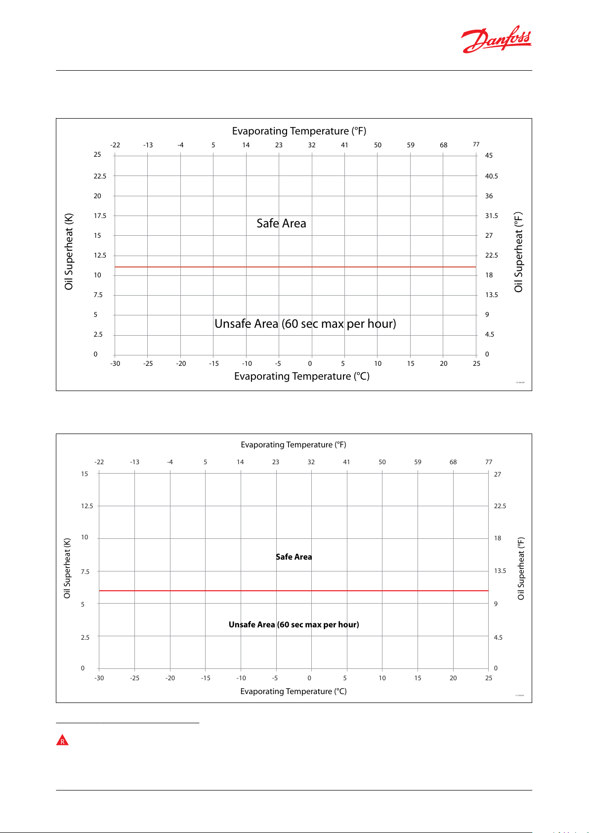
22.5
25
20
17.5
15
12.5
10
7.5
5
-25-30 -20 -15 -10 -5 0 5 10 15 20 25
-13-22 -4 5 14 23 32 41 50 59 68
77
2.5
0
40.5
45
36
31.5
27
22.5
18
13.5
9
4.5
0
Unsafe Area (60 sec max per hour)
Safe Area
Evaporating Temperature (°C)
Evaporating Temperature (°F)
Oil Superheat (K)
Oil Superheat (°F)
CC-000185
15
12.5
10
7.5
5
-25-30 -20 -15 -10 -5 0 5 10 15 20 25
-13-22 -4 5 14 23 32 41 50 59 68 77
2.5
0
27
22.5
18
13.5
9
4.5
0
CC-000026
Evaporating Temperature (°F)
Safe Area
Unsafe Area (60 sec max per hour)
Evaporating Temperature (°C)
Oil Superheat (K)
Oil Superheat (°F)
Scroll compressors, DSF090 to DSF530 | Application
Dilution Chart - DSF090 to DSF200, R32
Figure 51: Dilution Chart (reference at 20 °C / 68 °F ambient temperature)
Dilution Chart - DSF270 to DSF570, R32
Figure 52: Dilution Chart (reference at 20 °C / 68 °F ambient temperature)
Manage o cycle migration
O -cycle refrigerant migration happens:
© Danfoss | Climate Solutions | 2021.10 AB309735209512en-000401 | 44
Page 45

Application
BELOW charge limit
ABOVE charge limit
All
Ensure tightness between condenser & evaporator when system is OFF
• Thermostatic expansion Valve (TXV), Liquid Line Solenoid Valve LLSV strongly recommended
• Electronic expansion valve (EXV) must close when system stop including in power shut down situation
Non split
No test or additional safeties required
• Surface Sump Heater
Split
Since each installation is unique, refrigerant charge may vary
• Surface Sump Heater
• Liquid Line Solenoid Valve + pump-down cycle
Compressor Surrounding Ambient
Surface Sump Heater
Unit has enclosure, no wind
48W SSH
Unit has no enclosure, with wind
80W SSH
Unit has no enclosure, wind >5m/s (ft/s)& ambient temperature <-5°C
80W SSH + additional SSH/thermal insulation
Scroll compressors, DSF090 to DSF530 | Application
• when the compressor is located at the coldest part of the installation, refrigerant vapor condenses in the
compressor.
• or directly in liquid-phase by gravity or pressure dierence. When the compressor restarts, the refrigerant diluted
in the oil, or stored in evaporator, generates poor lubrication conditions, and may reduce bearings life time. In
extreme situations, this leads to liquid slugging that can damage the compressor scroll set.
Requirement
• Compressor can tolerate occasional ooded start, but it should remain exceptional situation and unit design must
prevent that this situation happen at each start.
• Right after start, liquid refrigerant must not ow massively to compressor
• The charge limit is a threshold beyond some protective measures must be taken to limit risk of liquid slugging and
extreme dilution at start.
System evaluation
Use the Table 27: Charge limits for Single models and Table 28: Charge limits for Tandem models in section Charge
limits, in relation with the system charge and the application to quickly dene necessary safeties to implement.
Table 25: System evaluation
Surface Sump heater
The surface sump heater are designed to protect the compressor against o-cycle migration of refrigerant.
For DSF090-200, the surface sump heater is located on the compressor shell. For better standby energy
consumption, Danfoss provides 48W and 80W two optional surface sump heater. The selection of surface sump
heater could be refered to below principle:
Figure 53: DSF090 to 200
Table 26: surface sump selection principle
For DSF270-530, the 56W surface sump heater is located below the sump, associated with a thermal insulation.
© Danfoss | Climate Solutions | 2021.10 AB309735209512en-000401 | 45
Page 46

Models
Composition
Refrigerant charge limit
kg
lbs
DSF090-818DSF100-818DSF115-1022DSF130-1022DSF155-1022DSF175-1022DSF200-1022DSF270-1533DSF325-1533DSF485-1737DSF530-17
37
Models
Composition
Refrigerant charge limit
kg
lbs
DSF180E
DSF090+DSF090
1226DSF200E
DSF100+DSF100
1226DSF230E
DSF115+DSF115
1226DSF260E
DSF130+DSF130
1226DSF215U
DSF100+DSF115
1226DSF230U
DSF100+DSF130
1226DSF255U
DSF100+DSF155
12
26
Scroll compressors, DSF090 to DSF530 | Application
Figure 54: DSF 270 to 530
The heater must be turned on whenever all the compressors are o. Surface sump heater accessories are available
from Danfoss (see section Accessories and spare parts).
Liquid line solenoid valve (LLSV)
A LLSV is used to isolate the liquid charge on the condenser side, thereby preventing against charge transfer to the
compressor during o -cycles. The quantity of refrigerant on the low-pressure side of the system can be further
reduced by using a pump-down cycle in association with the LLSV.
Pump-down cycle
By decreasing pressure in the sump, pump down system:
• evacuates refrigerant from oil
• set the sump saturating pressure much lower than ambiance temperature and due to that, avoid refrigerant
condensation in the compressor.
Pump-down must be set higher than 1.7 bar(g) (25 psig). For more details on pump-down cycle see Pump-down
logic recommendations in section Control logic.
Charge limits
Table 27: Charge limits for Single models
Table 28: Charge limits for Tandem models
© Danfoss | Climate Solutions | 2021.10 AB309735209512en-000401 | 46
Page 47

Models
Composition
Refrigerant charge limit
kg
lbs
DSF275U
DSF100+DSF175
1226DSF285U
DSF130+DSF155
1226DSF300U
DSF100+DSF200
1226DSF305U
DSF130+DSF175
1226DSF310E
DSF155+DSF155
1431DSF315U
DSF115+DSF200
1226DSF350E
DSF175+DSF175
1431DSF400E
DSF200+DSF200
1431DSF330U
DSF155+DSF175
1431DSF331U
DSF130+DSF200
1226DSF355U
DSF155+DSF200
1431DSF375U
DSF175+DSF200
1431DSF400X
DSF130+DSF270
1431DSF500X
DSF175+DSF325
1431DSF470X
DSF200+DSF270
1431DSF525X
DSF200+DSF325
1431DSF540E
2xDSF2702146
DSF595U
DSF270 + DSF325
2146DSF650E
2xDSF3252555
DSF800U
DSF270 + DSF530
2146DSF855U
DSF325 + DSF530
2555DSF970E
DSF485 + DSF485
3475DSF1060E
DSF530 + DSF530
34
75
Models
Composition
Refrigerant charge limit
kg
lbs
DSF465T
3 × DSF155
1431DSF525T
3 × DSF175
1431DSF600T
3 × DSF200
1431DSF810T
3 × DSF270
2146DSF975T
3 × DSF325
2555DSF1180T
DSF325+DSF325+DSF530
2555DSF1385T
DSF530+DSF530+DSF325
3475DSF1590T
3 × DSF530
34
75
Scroll compressors, DSF090 to DSF530 | Application
Table 29: Charge limits for Trio models
Power supply and electrical protection
Wiring information
Requirements
• Protect the compressor from short circuit and overcurrent by a thermal magnetic motor circuit breaker set to Max.
operating current or lower (see table in section Three phase electrical characteristics). For DSF090-200, phase
sequence protection is strongly recommended.
• DSF 270-530 compressors are delivered with a pre-installed motor protection module inside the terminal box that
must be powered on.
• HP safety switch and electronic module relay output (M1-M2) must be wired in the safety chain. Other safety
devices such as LP can be either hardware or software managed.
• Provide separate electrical supply for the heaters so that they remain energized even when the machine is out of
service (e.g. seasonal shutdown).
The wiring diagrams below are examples for a safe and reliable compressor wiring:
© Danfoss | Climate Solutions | 2021.10 AB309735209512en-000401 | 47
Page 48

M
DGT
HP
UC
SS CC
F1 F1
KM
CB
Ph
L1L1L3 L2
L3
L2
T1
T3
T2
KM
SSH
LPS
Ph
CC-0036
MPM
S
SSH
CCSS
LPS
KM
CB
F1 F1
HP
L1 L3 L2
KM
T2
M
T1
T3
DGT
UC
CC-0041
Scroll compressors, DSF090 to DSF530 | Application
Figure 55: Compressor model DSF090 - 200
Figure 56: Compressor model DSF270 - 325
© Danfoss | Climate Solutions | 2021.10 AB309735209512en-000401 | 48
Page 49

CB
CC
DGT
F1HPKM
LPSMMPM
S
SS
SSH
CC
SS
LPS
KM
F1 F1
HP
L1 L3 L2
KM
DGT
MPM
CB
UC
M
S
SSH
T2
T1
T3
CC-000020
Thermal magnetic motor circuit breaker
Control circuit
Discharge gas thermistor (embedded in com-
pressor)
Fuses
High pressure safety switch
Compressor contactor
Safety pressure switch
Compressor motor
Motor Protection Module
Thermistor chain (motor and discharge tem-
perature)
Seprate supply
Surface sump heater
Safeties
Tripping conditions
Re-start conditions
Value
Time
Value
Time
HP safety switch
See Pressure settings table
from section Operating enve-
lope data
Immediate, no delay. No bypass
Conditions back to normal.
Switch closed again.
Manual reset
LP safety switch
Maximum 5 auto reset during a
period of 12 hours, then manual reset.
Electronic module (Motor protection, DGT)
Contact M1-M2 opened
Scroll compressors, DSF090 to DSF530 | Application
Figure 57: Compressor model DSF485 - 530
Soft starts
Soft starters are designed to reduce the starting current of 3-phase AC motors. Soft starter must be set so
compressor start-up time is always less than 0.5 seconds to ensure proper lubrication of compressor parts.
Ramp-down must be set to minimum to ensure proper discharge valve closing.
Make sure that the soft starter selected is compatible with R32 refrigerant.
Control logic
Safety control logic requirements
Table 30: Safety control logic requirements
© Danfoss | Climate Solutions | 2021.10 AB309735209512en-000401 | 49
Page 50

1
Cp 1 ON
Cp 2 ON
H
100%
2 65 8 973
4
CC-000019
4WV
EXV
Scroll compressors, DSF090 to DSF530 | Application
Cycle rate limit requirements
Danfoss requires a minimum compressor running time of 2 minutes to ensure proper oil return and sucient motor
cooling.
Additionally, compressor must not exceed 12 starts per hour. 12 starts per hour must not be considered as an
average, this is the maximum number of starts acceptable to keep a good regulation accuracy during low load.
Oil management logic recommendations
In some cases, oil management can be enhanced by control logic:
• If oil return test failed, a function can be integrated in control logic to run all compressors simultaneously during 2
minutes every hour in order to boost oil return. Time and delay can be ne-tuned by oil return test No.1 in section
Manage oil in the circuit. During oil boost, pay special attention to superheat management to avoid liquid ood
back.
• In trio system, after running long time in same state with 2 or 3 compressors, (1+2+3) or (1+2), (2+3) or (3+1), oil
unbalance may appears. A function can be implemented in control logic to stop all compressors during one
minute every two hours in order to balance oil. Time and sequence can be ne-tuned during Oil balancing test in
section Manage oil in the circuit.
Defrost logic recommendations / Reversible systems
In reversible systems, the defrost logic can be worked out to limit liquid ood back eect by:
1.
Running full load during defrost to share liquid refrigerant between all compressors.
2.
Reducing refrigerant ooding to compressor by transferring liquid refrigerant from one exchanger to the other
before reversing valve thanks pressures.
The following defrost logic combines both advantages:
Figure 58: Defrost logic advantages
© Danfoss | Climate Solutions | 2021.10 AB309735209512en-000401 | 50
Page 51

Cp 1
Cp 2ONH
12345
6789Compressor 1
Compressor 2
On
Heating
Defrost start. Stop all compressors
4 Way Valve (4WV) stays in heating mode. EXV opened to transfer liquid from outdoor to indoor
exchanger thanks to pressure dierence.
When pressures are almost balanced
(1)
, change 4WV to cooling mode.
Start Cp1 and Cp 2 with 0.5 seconds delay between 2 successive starts
Defrost
Defrost end. Stop all compressors
4 WV stays in cooling mode. EXV opened to transfer liquid from indoor to outdoor exchanger thanks to
pressure dierence
When pressures are almost balanced
(1)
, change 4WV to heating mode.
Start Cp1 and Cp 2 with 0.5 seconds delay between 2 successive starts
Scroll compressors, DSF090 to DSF530 | Application
In reversible systems, to ensure compressor reliability, the 4-way valve must not reverse when the compressor is
stopped due to heating or cooling demand (stop on thermostat).
(1)
(1)
EXV Opening degree and time have to be set to keep a minimum pressure for 4 way valve moving. In any case, defrost logics must respect
EXV Opening degree and time have to be set to keep a minimum pressure for 4 way valve moving. In any case, defrost logics must respect
requirements and tests described in sections Manage superheat and Operating envelope data.
requirements and tests described in sections Manage superheat and Operating envelope data.
Pump-down logic recommendations
Pump down is initiated prior to shutting down the last compressor on the circuit by de-energizing a liquid line
solenoid valve or closing electronic expansion valve. When suction pressure reached the cut-out pressure,
compressor is stopped, and liquid solenoid valve or electronic expansion valve remains closed.
Two types of pump-down exist:
• One shot pump down (preferred): when last compressor of the circuit stops, suction presssure is decreased 1.5 bar
(22 psi) below nominal evaporating pressure with minimum of 1.7 bar(g) (25 psig). Even if suction pressure
increases again, the compressor will not restart.
• Continuous pump-down: traditional pump-down, Compressor restarts automatically when suction pressure
increases up to 4 cycles maximum.
Non Return Valve (NRV)
DSF compressors integrate tight internal non return valve (INRV), therefore no external Non Return Valve (NRV) is
needed.
Reduce moisture in the system
Excessive air and moisture
• can increase condensing pressure and cause high discharge temperatures.
• can create acid giving rise to copper platting.
• can destroy the lubricating properties of the oil.
All these phenomena can reduce service life and cause mechanical and electrical compressor failure.
© Danfoss | Climate Solutions | 2021.10 AB309735209512en-000401 | 51
Page 52

Scroll compressors, DSF090 to DSF530 | Application
Requirements
DSF compressors are delivered with < 100 ppm moisture level.
At the time of commissioning, system moisture content may be up to 100 ppm.
During operation, the lter drier must reduce this to a level between 20 and 50 ppm.
Solutions
To achieve this requirement, a properly sized and type of drier is required.
Important selection criteria’s include:
• driers water content capacity
• system refrigeration capacity
• system refrigerant charge
For new installations with DSF compressors with polyolester oil, Danfoss recommends using the Danfoss DML
(100% molecular sieve) solid core lter drier.
Assembly line procedure
Compressor storage
Store the compressor not exposed to rain, corrosive or ammable atmosphere between -35 °C (-31 °F) and 70 °C
(158 °F) when charged with nitrogen and between -35 °C (-31 °F) and Ts max value (see section Pressure equipment
directive 2014/68/EU) when charged with refrigerant.
Compressor holding charge
Each compressor is shipped with a nominal dry nitrogen holding charge between 0.3 bar (4 psi) and 0.7 bar (10 psi)
and is sealed with elastomer plugs.
Respect the following sequence to avoid discharge check valve gets stuck in open position:
• Remove the suction plug rst
• Remove the discharge plug afterwards
An opened compressor must not be exposed to air for more than 20 minutes to avoid moisture is captured by
the POE oil.
Handling
Each Danfoss DSF scroll compressor is equipped with two lift rings on the top shell.
• Always use both these rings when lifting the compressor.
• Use lifting equipment rated and certied for the weight of the compressor or compressor assembly.
• A spreader bar rated for the weight of the compressor is highly recommended to ensure a better load distribution.
• The use of lifting hooks closed with a clasp is recommended.
• For tandem and trio assemblies, use a spreader bar and all compressor rings as shown in picture below.
• Never use the lift rings on the compressor to lift the full unit.
Maintain the compressor in an upright position during all handling manoeuvres (maximum of 15° from vertical).
© Danfoss | Climate Solutions | 2021.10 AB309735209512en-000401 | 52
Page 53

HEAVY
do not lift
manually
123
3
2
1
cc-0066
Slings
Spreader bars
Frame
Circuit contamination possible cause
Requirement
Brazing and welding oxides
During brazing,
ow nitrogen through the system.
Particles and burrs
Remove any particles and burrs generated by tube cutting and hole drilling.
Moisture and air
Use only clean and dehydrated refrigeration grade copper tubing.
Opened compressor must not be exposed to air more than 20 minutes to avoid moisture captured by oil.
Scroll compressors, DSF090 to DSF530 | Application
Figure 59: Heavy
Figure 60: Correct Figure 61: Incorrect
Figure 62: Handling
Piping assembly
Good practices for piping assembly is a pre-requisite to ensure compressor life time (system cleanliness, brazing
procedure etc.)
Table 31: System cleanliness
Brazing procedure:
• Brazing operations must be performed by qualied personnel.
• Make sure that no electrical wiring is connected to the compressor.
• To prevent compressor shell and electrical box overheating, use a heat shield and/or a heat-absorbent compound.
• Clean up connections with degreasing agent.
• Flow nitrogen through the compressor.
• Use ux in paste or ux coated brazing rod.
• Use brazing rod with a minimum of 5% silver content.
• It is recommended to use double-tipped torch using acetylene to ensure a uniform heating of connection.
• For discharge connections brazing time should be less than 2 minutes to avoid NRVI damages if any.
• To enhance the resistance to rust, a varnish on the connection is recommended.
DSF compressors connectors are made of steel copper coated, which benet to protect against corrosion and
facilitate adhesion during brazing operation.
As per standards practice in the refrigeration industry, Danfoss Commercial Compressor recommend to use of silver
cadmium free solder alloy and ux (added or ux coated rods). The signicant silver content in these brazing alloy
will help the brazing operation, providing an excellent uidity and a limited heating temperature. It will bring also a
good resistance to corrosion, a proper elongation compatible with system vibration, and good behavior under
thermal variation improving the strength of connection and limiting fractures and refrigerant leaks. (Crucial with
A2L refrigerants).
A typical content of 30 – 40% Ag (Silver) is recommended by Danfoss.
© Danfoss | Climate Solutions | 2021.10 AB309735209512en-000401 | 53
Page 54

CC-0052
1
1
Heat shield
Maximum compressor test pressures
DSF090-200
DSF270-325-485-530
Maximum compressor test pressure high side (HP)
53.6 bar (g) (777 psig)
HP-LP<37 bar (537 psi)
53.6 bar (g) (777 psig)
HP-LP<37 bar (537 psi)
Maximum compressor test pressure low side (LP)
36.7 bar (g) (533 psig)
LP – HP <5 bar (73 psi)
Maximum speed 4.8 bar/s (70 psi/s)
34.3 bar (g) (497 psig)
LP – HP <5 bar (73 psi)
Maximum speed 4.8 bar/s (70 psi/s)
(1)
Scroll compressors, DSF090 to DSF530 | Application
The use of self-ux alloys (as phosphorous alloys) is not recommended by Danfoss. This type of brazing require a
higher working temperature, that may overheat the connectors, damaging the thin layer of copper, resulting in
phosphides creation and joint zone embrittlement.
For more detailed information see "Brazing technique for compressors connectors" AP192186420580.
Before eventual un-brazing of the compressor or any system component, the refrigerant charge must be
removed and the installation vacuumed.
System pressure test and leak detection
The compressor has been strength tested and leak proof tested (<3g/year) at the factory. For system tests:
• Always use an inert gas such as Nitrogen or Helium.
• Pressurize the system on HP side rst then LP side.
• Do not exceed the following pressures indicated in table below.
Table 32: System pressure test and leak detection
(1)
(1)
DSF compressors have an internal non return valve
DSF compressors have an internal non return valve
equalization between LP and HP side over scroll elements.
equalization between LP and HP side over scroll elements.
tting: the maximum pressurizing speed must be respected to ensure pressure
tting: the maximum pressurizing speed must be respected to ensure pressure
Vacuum evacuation and moisture removal
Requirements:
• Never use the compressor to evacuate the system.
• Connect a vacuum pump to both the LP and HP sides.
• Evacuate the system to a pressure of 500 μm Hg (0.67 mbar/0.02 in.Hg) absolute.
Recommendations:
• Energized heaters improve moisture removal.
• Alternate vacuum phases and break vacuum with Nitrogen to improve moisture removal.
For more detailed information see “Vacuum pump-down and dehydration procedure” AP000086424630en.
Refrigerant charging
Initial charge:
© Danfoss | Climate Solutions | 2021.10 AB309735209512en-000401 | 54
Page 55

Scroll compressors, DSF090 to DSF530 | Application
• For the initial charge, the compressor must not run.
• Charge refrigerant as close as possible to the nominal system charge.
• This initial charging operation must be done in liquid phase between the condenser outlet and the lter drier.
If needed, a complement of charge can be done before evaporator, in liquid phase while compressor is running by
slowly throttling liquid in.
Never bypass safety low pressure switch.
For more detailed information see “Recommended refrigerant system charging practice“ AP000086421422.
Dielectric strength and insulation resistance tests
Several tests have been performed on each compressor at the factory between each phase and ground.
• Dielectric strength test is done with a high potential voltage (hi-pot) of 2Un +1000 V AC at least, and leakage
current must be less than 5 mA.
• Insulation resistance is measured with a 500 V DC megohm tester and must be higher than 1 megohm.
Recommendations:
• Additional dielectric test is not recommended as it may reduce motor lifetime. Nevertheless, if such as test is
necessary, it must be performed at a lower voltage.
• Insulation resistance test can be done.
• The presence of refrigerant around the motor windings will result in lower resistance values to ground and higher
leakage current readings. Such readings do not indicate a faulty compressor. To prevent this, the system can be
rst operated briey to distribute refrigerant.
Do not use a megohm meter nor apply power to the compressor while it is under vacuum as this may cause
internal damage.
Commissioning
Preliminary check
Check electrical power supply:
• Phase order: Reverse rotation is obvious if the compressor do not build up pressure and sound level is abnormal
high
DSF compressors are equipped with an electronic module: reverse rotation will be automatically detected. For more
details refer to section Motor protection.
• Voltage and voltage unbalance within tolerance: For more details refer to section Motor voltage.
Initial start-up
• Surface sump heaters must be energized at least 6 hours in advance to remove refrigerant.
• A quicker start-up is possible by “jogging” the compressor to evacuate refrigerant. Start the compressor for 1
second, then wait for 1 to 2 minutes. After 3 or 4 jogs the compressor can be started. This operation must be
repeated for each compressor individually.
System monitoring
The system must be monitored after initial startup for a minimum of 60 minutes to ensure proper operating
characteristics such as:
• Correct superheat and subcooling.
• Current draw of individual compressors within acceptable values (max operating current).
• No abnormal vibrations and noise.
• Correct oil level.
© Danfoss | Climate Solutions | 2021.10 AB309735209512en-000401 | 55
Page 56

Scroll compressors, DSF090 to DSF530 | Application
If Oil Top-up is needed, it must be done while the compressor is idle. Use the schrader connector or any other
accessible connector on the compressor suction line. Always use original Danfoss POE oil 185SL from new cans. For
more detailed information see “Lubricants lling in instructions for Danfoss Commercial Compressors”
AP000086435866.
Dismantle and disposal
Danfoss recommends that compressors and compressor oil should be recycled by a suitable company at its
site.
© Danfoss | Climate Solutions | 2021.10 AB309735209512en-000401 | 56
Page 57

Compressor
model
Length
Width
Height
Gross weight
mm
inchmminchmminchkglbs
DSF090
565
22.2
470
18.5
718
28.369152
DSF100
565
22.2
470
18.5
718
28.369152
DSF115
565
22.2
470
18.5
718
28.376168
DSF130
565
22.2
470
18.5
718
28.376168
DSF155
565
22.2
470
18.5
718
28.379174
DSF175
565
22.2
470
18.5
718
28.381179
DSF200
565
22.2
470
18.5
718
28.384185
DSF240
760
29.9
600
23.6
99239124
273
DSF295
760
29.9
600
23.6
99239127
279
DSF485
760
29.9
600
23.6
99239191
420
DSF530
760
29.9
600
23.6
99239191
420
Compressor
model
Nbr
(1)
Length
Width
Height
Gross weight
Static stack‐
ing pallets
mm
inchmminchmminchkglbs
DSF09081150
45.3
950
37.4
680
26.8
494
10892DSF10081150
45.3
950
37.4
680
26.8
494
10892DSF11581150
45.3
950
37.4
750
29.5
544
11992DSF13081150
45.3
950
37.4
750
29.5
544
11992DSF15581150
45.3
950
37.4
750
29.5
566
12482DSF17581150
45.3
950
37.4
750
29.5
582
12832DSF20081150
45.3
950
37.4
750
29.5
606
13362DSF27061150
45.3
96538768
30.2
693
15282DSF32561150
45.3
96538768
30.2
712
15702DSF48541150
45.3
96538800
31.5
744
16402DSF53041150
45.3
96538800
31.5
744
1640
2
Scroll compressors, DSF090 to DSF530 | Packaging
Packaging
Single pack
Table 33: Single pack
Industrial pack
Table 34: Industrial pack
(1)
(1)
Number of compressors per pack.
Number of compressors per pack.
© Danfoss | Climate Solutions | 2021.10 AB309735209512en-000401 | 57
Page 58

Compressor model
Connections
Motor protection
Code no.
347
9
200-230/3/60
380-400 (415)/3/50
460/3/60
575/3/60
380-400/3/60
DSF090
Brazed
Internal
-
120H1635--
DSF100
Brazed
Internal
-
120H1637--
DSF115
Brazed
Internal
-
120H1639--
DSF130
Brazed
Internal
-
120H1503--
DSF155
Brazed
Internal
-
120H1475--
DSF175
Brazed
Internal
-
120H1477--
DSF200
Brazed
Internal
-
120H1479--
DSF270
Brazed
Module 24 V AC
(1)
-
120H1422--
Brazed
Module 110 – 240 V
(1)
-
120H1424--
DSF325
Brazed
Module 24 V AC
(1)
-
120H1426--
Brazed
Module 110 – 240 V
(1)
-
120H1428--
DSF485
Brazed
Module 24 V AC
(1)
-
120H1446--
Brazed
Module 110 – 240 V
(1)
-
120H1448--
DSF530
Brazed
Module 24 V AC
(1)
-
120H1430--
Brazed
Module 110 – 240 V
(1)
-
120H1432--
Scroll compressors, DSF090 to DSF530 | Ordering
Ordering
Compressor code numbers
Danfoss scroll compressors DSF can be ordered in either industrial packs or in single packs. Please use the code
numbers from below tables for ordering.
For compressors DSF270 to DSF530 use in single applications, exible grommets are available as accessory kit
8156138.
Single pack
Table 35: Single pack
(1)
(1)
Electronic motor protection, module located in terminal box.
Electronic motor protection, module located in terminal box.
NOTE:
Mounting kit for DSF270 to DSF530 single compressor applications: Ref 8156138.
Industrial pack
© Danfoss | Climate Solutions | 2021.10 AB309735209512en-000401 | 58
Page 59

Compressor model
Connections
Motor protection
Code no.
347
9
200-230/3/60
380-400 (415)/3/50
460/3/60
575/3/60
380-400/3/60
DSF090
Brazed
Internal
-
120H1636--
DSF100
Brazed
Internal
-
120H1638--
DSF115
Brazed
Internal
-
120H1640--
DSF130
Brazed
Internal
-
120H1502--
DSF155
Brazed
Internal
-
120H1474--
DSF175
Brazed
Internal
-
120H1476--
DSF200
Brazed
Internal
-
120H1478--
DSF270
Brazed
Module 24 V AC
(1)
-
120H1423--
Brazed
Module 110 – 240 V
(1)
-
120H1425--
DSF325
Brazed
Module 24 V AC
(1)
-
120H1427--
Brazed
Module 110 – 240 V
(1)
-
120H1429--
DSF485
Brazed
Module 24 V AC
(1)
-
120H1447--
Brazed
Module 110 – 240 V
(1)
-
120H1449--
DSF530
Brazed
Module 24 V AC
(1)
-
120H1431--
Brazed
Module 110 – 240 V
(1)
-
120H1433--
Scroll compressors, DSF090 to DSF530 | Ordering
Table 36: Industrial pack
(1)
(1)
Electronic motor protection, module located in terminal box.
Electronic motor protection, module located in terminal box.
© Danfoss | Climate Solutions | 2021.10 AB309735209512en-000401 | 59
Page 60

Code no.
Description
Application
Packaging
Pack size
8156132
Gasket, 1"3/4
Models with 1"3/4 rotolock connection
Multipack108156133
Gasket, 2"1/4
Models with 2"1/4 rotolock connection
Multipack107956003
Gasket, 1"3/4
Models with 1"3/4 rotolock connection
Industry pack507956004
Gasket, 2"1/4
Models with 2"1/4 rotolock connection
Industry pack
50
Code no.
Description
Application
Packaging
Pack size
8153004
Solder sleeve P02 (1"3/4 Rotolock - 1"1/8 ODF)
Models with 1"3/4 rotolock connection
Multipack108153006
Solder sleeve P03 (2"1/4 Rotolock - 1"5/8 ODF)
Models with 2"1/4 rotolock connection
Multipack
10
Code no.
Description
Application
Packaging
Pack size
8153124
Rotolock nut,1"3/4
Models with 1-3/4" rotolock connection
Multipack108153126
Rotolock nut, 2"1/4
Models with 2-1/4" rotolock connection
Multipack
10
Code no.
Description
Application
Packaging
Pack size
120Z0584
Electronic motor protection module, 24 V AC
DSF270-530
Single pack1120Z0585
Electronic motor protection module, 110/240 V
DSF270-530
Single pack
1
Scroll compressors, DSF090 to DSF530 | Accessories and spare parts
Accessories and spare parts
Gaskets
Table 37: Gaskets
Solder sleeve
Table 38: Solder sleeve
Rotolock nut
Table 39: Rotolock nut
Motor protection modules
Table 40: Motor protection modules
© Danfoss | Climate Solutions | 2021.10 AB309735209512en-000401 | 60
Page 61

Code no.
Description
Application
Packaging
Pack size
120Z0388
80W 24V surface sump heater CE and UL
DSF090 to 200
Multipack
8
120Z0389
80W 230V surface sump heater CE and UL
DSF090 to 200
Multipack
8
120Z0390
80W 400V surface sump heater CE and UL
DSF090 to 200
Multipack
8
120Z0391
80W 460V surface sump heater CE and UL
DSF090 to 200
Multipack
8
120Z0402
80W 575V surface sump heater CE and UL
DSF090 to 200
Multipack
8
120Z0667
48W 24V surface sump heater CE and UL
DSF090 to 200
Single pack
1
120Z0668
48W 230V surface sump heater CE and UL
DSF090 to 200
Single pack
1
120Z0669
48W 400V surface sump heater CE and UL
DSF090 to 200
Single pack
1
120Z0670
48W 460V surface sump heater CE and UL
DSF090 to 200
Single pack
1
120Z0671
48W 575V surface sump heater CE and UL
DSF090 to 200
Single pack
1
120Z0769
56W 24V surface sump heater + bottom insulation, CE & UL
DSF270-530
Multipack
6
120Z0770
56W 230V surface sump heater + bottom insulation, CE & UL
DSF270-530
Multipack
6
120Z0771
56W 400V surface sump heater + bottom insulation, CE & UL
DSF270-530
Multipack
6
Code no.
Description
Application
Packaging
Pack size
120Z0066
Mounting kit for scroll compressors. Grommets, sleeves, bolts, washers
DSF090 to 200
Single pack18156138
Mounting kit for scroll compressors. Grommets, sleeves, bolts, washers
DSF270-530 in single installation
Single pack
1
7777045
Mounting kit for scroll compressors. including hexagon rigid spacers,
Grommets, Sleeves, Bolts, Washers
DSF270 to 530 Manifold installations 50 Hz when mounting directly on rail is not wished
Single pack
1
Code no.
Description
Packaging
Pack size
120Z0750
POE lubricant 185SL, 1 litre can
Multipack
12
Scroll compressors, DSF090 to DSF530 | Accessories and spare parts
Surface sump heaters
Table 41: Surface sump heaters
Mounting hardware
Table 42: Mounting hardware
Lubricant
Table 43: Lubricant
© Danfoss | Climate Solutions | 2021.10 AB309735209512en-000401 | 61
Page 62

Code no.
Description
Application
Packaging
Pack Size
8156135
Service kit for terminal box 96 x 115 mm, including 1 cover, 1 clamp
DSF090 to 175
Multipack
10
8173230
T block connector 52 x 57 mm
DSF090 to 175
Multipack
10
8173021
T block connector 60 x 75 mm
DSF200
Multipack
10
120Z0413
Terminal box cover
DSF200
Single pack1120Z0458
Terminal box 210 x 190 mm, incl. cover
DSF270-530
Single pack1120Z0774
T block connector 80x80 mm
DSF270-530
Multipack
10
Code no.
Description
Application
Packaging
Pack Size
120Z0768
Acoustic hood DSF large scroll
DSF270-530
Single pack
1
Code no.
Description
Packaging
Pack Size
8156019
Sight glass with gaskets (black & white)
Multipack48156129
Gasket for oil sight glass, 1"1/8 (white
teon)
Multipack107956005
Gasket for oil sight glass, 1"1/8 (white
teon)
Multipack508154001
Danfoss Commercial Compressors blue spray paint
Single pack
1
Scroll compressors, DSF090 to DSF530 | Accessories and spare parts
Terminal boxes, covers and T-block connectors
Table 44: Terminal boxes, covers and T-block connectors
Acoustic hoods
Table 45: Acoustic hoods
Miscellaneous
Table 46: Miscellaneous
Tandem kits
© Danfoss | Climate Solutions | 2021.10 AB309735209512en-000401 | 62
Page 63

Code no.
Description
Application
Packaging
Pack Size
120Z0634
Suction washer, rigid spacer, organ pipe, gasket
DSF260E-310E-DSF350E-DSF400E
Single pack1120Z0692
Suction washer, rigid spacer, organ pipe, gasket
DSF285U-305U-330U
Single pack1120Z0693
Suction washer, rigid spacer, organ pipe, gasket
DSF300U-315U
Single pack1120Z0694
Suction washer, rigid spacer, organ pipe, gasket
DSF331U-355U-DSF375U
Single pack1120Z0781
Kit tandem crossplatform
DSF400X-470X-DSF500X-DSF525X
Single pack1120Z0786
Kit tandem, solid,washer 24mm,OEL 1" 5/8
DSF800U
Single pack1120Z0787
Kit tandem, solid,washer 27mm,OEL 1" 5/8
DSF855U
Single pack1120Z0785
Kit tandem, solid, OEL 1"5/8
DSF970E-1060E
Single pack1120Z0792
Kit tandem, solid,OEL 1" 3/8
DSF540E-650E
Single pack1120Z0796
Kit tandem, solid,washer 31mm,OEL 1" 3/8
DSF595U
Single pack
1
Code no.
Description
Application
Packaging
Pack Size
120Z0714
Organ pipe, sleeves, rigid spacer, gasket, rubber
grommet
DSF465T-DSF525T-DSF600T
Single pack
1
120Z0784
Kit trio, solid,washer 30 mm, OEL 1" 5/8
DSF810T-975T (left suction)
Single pack1120Z0790
Kit Trio,solid, OEL 1”5/8
DSF1180T (left suction)
Single pack1120Z0793
Kit trio, solid,washer 33 mm, OEL 1" 5/8
DSF1590T (left and right suction)
Single pack1120Z0794
Kit trio, solid,washer 34.5 mm, OEL 1" 5/8
DSF810T-975T (right suction)
Single pack1120Z0814
Kit Trio,solid,washer 26mm, OEL 1”5/8
DSF1385T ( left and right suction)
Single pack1120Z0815
Kit Trio,solid,washer 29mm (x2), OEL 1”5/8
DSF1180T (right suction)
Single pack
1
Scroll compressors, DSF090 to DSF530 | Accessories and spare parts
Table 47: Tandem kits
Trio kits
Table 48: Trio kits
© Danfoss | Climate Solutions | 2021.10 AB309735209512en-000401 | 63
Page 64
Online support
Danfoss oers a wide range of support along with our products, including digital product information, software,
mobile apps, and expert guidance. See the possibilities below.
The Danfoss Product Store
The Danfoss Product Store is your one-stop shop for everything product related—no matter where
you are in the world or what area of the cooling industry you work in. Get quick access to essential
information like product specs, code numbers, technical documentation, certications, accessories,
and more.
Start browsing at store.danfoss.com.
Find technical documentation
Find the technical documentation you need to get your project up and running. Get direct access to
our ocial collection of data sheets, certicates and declarations, manuals and guides, 3D models
and drawings, case stories, brochures, and much more.
Start searching now at www.danfoss.com/en/service-and-support/documentation.
Danfoss Learning
Danfoss Learning is a free online learning platform. It features courses and materials specically
designed to help engineers, installers, service technicians, and wholesalers better understand the
products, applications, industry topics, and trends that will help you do your job better.
Create your Danfoss Learning account for free at www.danfoss.com/en/service-and-support/learning.
Get local information and support
Local Danfoss websites are the main sources for help and information about our company and
products. Find product availability, get the latest regional news, or connect with a nearby expert—all
in your own language.
Find your local Danfoss website here: www.danfoss.com/en/choose-region.
Coolselector®2 - nd the best components for you HVAC/R system
Coolselector®2 makes it easy for engineers, consultants, and designers to nd and order the best
components for refrigeration and air conditioning systems. Run calculations based on your operating
conditions and then choose the best setup for your system design.
Download Coolselector®2 for free at coolselector.danfoss.com.
Ref Tools – essential tools for HVACR professionals
Get the guidance, support, information, and tools you need—on the job and in eld. Ref Tools is a
free, powerful app that contains essential tools every air conditioning and refrigeration technician
needs in their digital toolbelt.
Download Ref Tools for free at coolapps.danfoss.com
Any information, including, but not limited to information on selection of product, its application or use, product design, weight, dimensions, capacity or any other
technical data in product manuals, catalogues descriptions, advertisements, etc. and whether made available in writing, orally, electronically, online or via download,
shall be considered informative, and is only binding if and to the extent, explicit reference is made in a quotation or order conrmation. Danfoss cannot accept any
responsibility for possible errors in catalogues, brochures, videos and other material. Danfoss reserves the right to alter its products without notice. This also applies to
products ordered but not delivered provided that such alterations can be made without changes to form, t or function of the product. All trademarks in this material
are property of Danfoss A/S or Danfoss group companies. Danfoss and the Danfoss logo are trademarks of Danfoss A/S. All rights reserved.
© Danfoss | Climate Solutions | 2021.10 AB309735209512en-000401 | 64
 Loading...