

Page 1
Data sheet
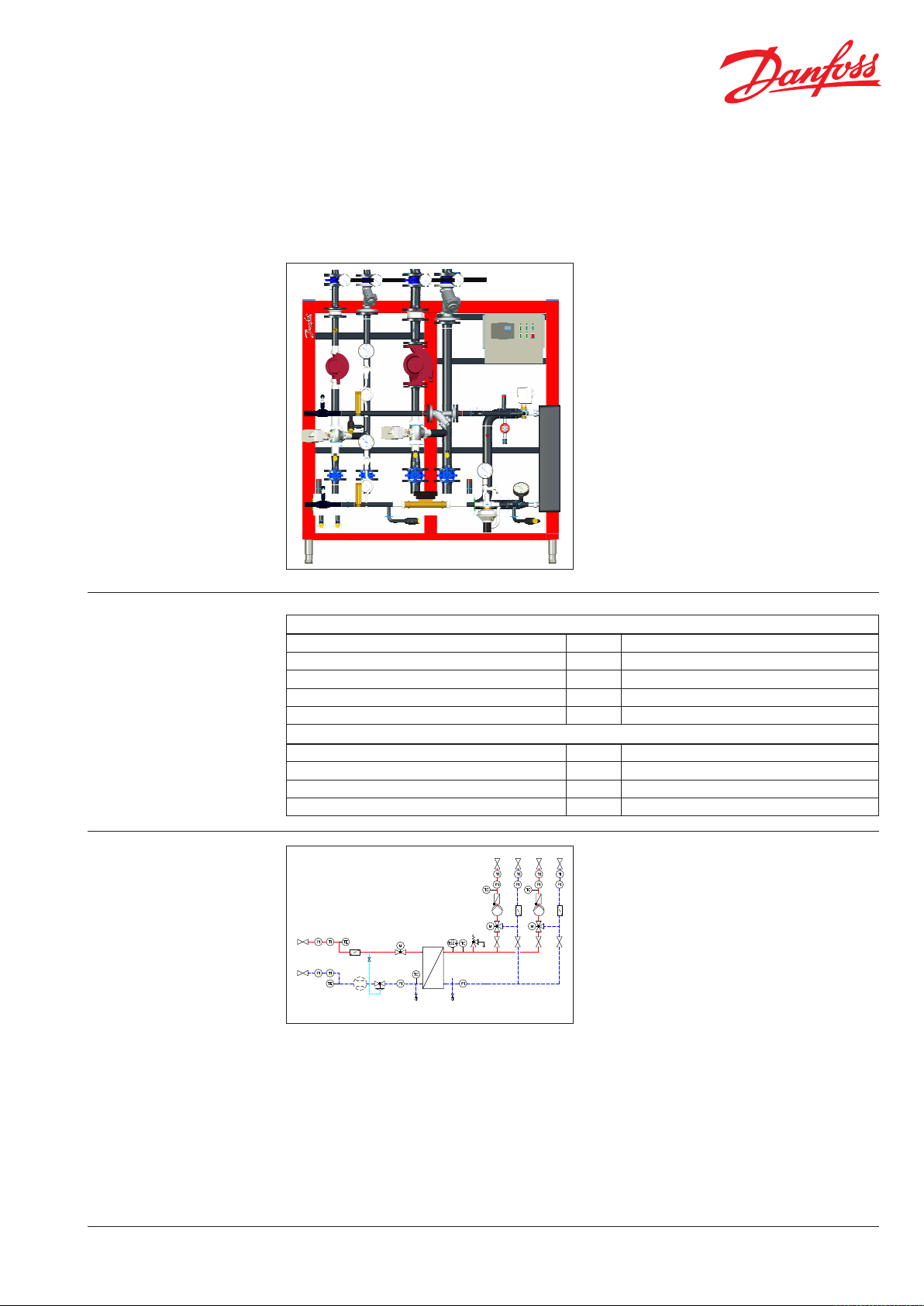
Welded District Heating Stations
Type DSE-I1B (two secondary heating circuits)
General description and
application
Maximum operating
parameters
District heating transfer stations provide the
link between district heating suppliers
and customers’ systems.
They incorporate the necessary equipment to
tailor the supplied heat to the needs of the object
premises as specied in the heating supply contract.
In this they need to comply with all applicable
standards and with the supplier’s technical
connection conditions.
Indirect connections (in which district heating
and in-house systems are hydraulically isolated)
incorporate components to separate the systems
(heat exchanger), to limit the ow volume to that
specied in the contract, regulate the secondary
supply temperature and measure the energy
consumption.
The system described here is a standard type in
which the secondary incorporates two regulatory /
heating circuits.
Primary
Maximum permissible supply temperature, primary
Maximum permissible operating pressure, primary PZP 25 or 16 bar (g)
Rated pressure, primary PN 25 or 16
Maximum permissible pressure dierential, primary
Maximum permissible ow volume, primary VZP 9.0 m
TVP 150 °C
DPP 20 bar (-kvs=8 m3/h) / 16 bar (kvs=12.5-20 m3/h)
3
/h for w <= 1.2 m/s
Secondary
Maximum permissible supply temperature, secondary
Maximum permissible operating pressure, secondary PZS 10 bar or depending on the safety valve
Rated pressure, secondary PN 10
Maximum permissible ow volume, secondar y VZS 25.0 m
TVS 110 °C
3
/h for w <= 1.2 m/s
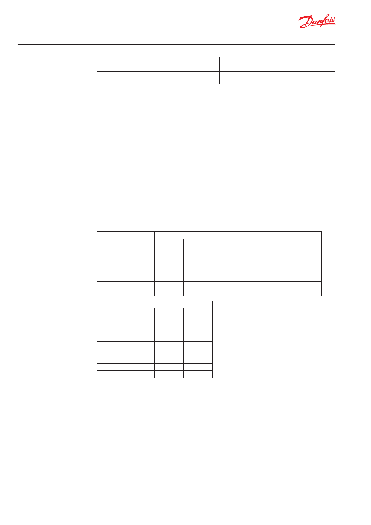
Circuit diagram
DEN-SMT/PL
0211
0212
0411
0412
0421
0522
0532
0450
0451
02310111
0122
0132
1211 1212
0422
0450
0451
02320112
0521
0531
0251 0252
0121
0430
0400
0431
0401
0200
0220
0430
0400
0431
0401
0020
0021
0010
0011
0510
0511
0430
0431
0270 0280
0012
0033
0030
0040
0131
0520
0530
0100
0560
0561
MAG
0440
0441
Options
Instead of the 0020/0030 the system can also
incorporate a combined ow/temperature
regulator (combo-valve), which can be installed
in the supply or return line as desired.
VD.HE.E2.02 © Danfoss 05/2012
Legend
0200/21x Shut-o device for primary/secondary
121x Shut-o device for secondary distributor
0430/431 Manometer with shut-o valve
0400/401 Thermometer with immersion sleeve
0220/23x Dirt trap / strainer
0040 Fitting piece for energy meter
0020 Motor regulator valve
0021 Electrical actuator
0030 Pressure dierential and ow regulator
0033 Needle valve
0270 High-pressure drain valve
0510/511 Return temperature limiter
0010-12 Heat exchanger with insulation
0560/561 Safety thermostat
052x/53x Supply temperature sensor
0100 Safety valve
0280 Drain valve
044x/045x Manometer with shut-o valve
MAG Pressure retention connector
041x/42x Thermometer with immersion sleeve
011x Circulation pump
025x Non-return valve
012x/013x Mixing valve with electrical actuator
1
Page 2
Data sheet Welded District Heating Stations Type DSE-I1B (two secondary heating circuits)
Materials
Function
Technical data
Pipes and pipe ttings, anges P235GH-TC1, C22.8
Heat exchanger 1.4404 with Cu brazing compound
Fittings CuSn5Pb5Zn5-C (RG-5), ST37.0,
Hot water drawn from the pipeline of the local or
district heating supply company is fed into the
station at an appropriate temperature and pressure,
EN-GJS-400-18-LT (GGG40.3)
The cooled heating water then ows back to the
local or district heating supply company via the
primary return pipe.
which may be higher in winter than in summer.
A pump in the secondary circuit of the in-house
In the primary supply line this hot water will
generally ow through a shut-o valve and
a dirt trap / strainer.
Depending on the system design and the
stipulations of the heating provider, both the
supply and return lines will normally incorporate
system then circulates the hot water to the heating
surfaces or other consumers (e.g. ventilators,
domestic hot-water systems, etc.).
Additional heating circuits incorporate valves to
regulate the secondary temperatures to suit the
specic parameters of the heating circuit.
a thermometer and a manometer to register the
temperature and pressure.
There will also be regulatory equipment in the
supply or return lines of the primary as specied
by the requirements and the circuit design.
Primary Secondary (largest heating circuit)
max. V
p
DN
20 1.8 40 6,0 32-120 16.0 55
25 2.5 50 9,0 40-120 25.0 50
32 3.5 50 10,0 50-120 40.0 65
40 5.7 65 15,0 50-120 40.0 55
50 7.3 80 20,0 65-120 63.0 50
65 9.0 80 25,0 65-120 63.0 30
[m3/h]
DN max.
max. Vp
[m3/h]
Pump
MAGNA
(*)
Mixer valve
[m3/h]
k
vs
Residual delivery head
[kPa]
Primary control valve (20/30) / EM (40)
Dimen-
k
DN
20 .. 4.0 .. 2.5 1 x 190
25 6.3 3.5 ⁄ x 260
32 8.0 3.5 ⁄ x 260
40 12.5 6 ⁄ x 260
50 16.0 10 2 x 300
65 20.0 10 2 x 300
Types:
0020/21 VM2/AMV10/13/20/23 (*) other pumps on request
0030 AVPQ or AVPB 0121/31 VRG/AMV435 or VF3/AMV55
0020/21 AVQM/AMV10/13/20/23(SL)
(alternative)
vs
[m3/h]
QN
sions
G [‘’] * L
[mm]
2
VD.HE.E2.02 © Danfoss 05/2012
DEN-SMT/PL
Page 3

Data sheet Welded District Heating Stations Type DSE-I1B (two secondary heating circuits)
Dimensions
Dimensions
sec.DN
pr. DN
pr.
TWE
(max.)
20 - 40 1600 1600 750 ~ 790 1500 1660 557 410 210
25 - 50 1600 1600 750 750 1520 1715 557 410 210
32 - 50 1600 1770 800 ~ 870 1430 1865 688 440 200
40 - 65 1600 1855 800 ~ 920 1430 1865 672 440 200
50 - 80 1800 2110 900 ~ 1075 1520 1995 744 520 240
65 - 80 1800 2160 900 ~ 1110 1520 1995 748 520 240
* Dependi ng on the number of plates in the h eat exchanger
f the foot can be ad justed between: 105 … 160 mm
Width Depth Height Distance
b B t T* h H p w s
Example of performance
Primary
[m3/h]
V
p
Secondary
V
[m3/h] 0100
p
0010
Type
1.8 5.9 R1-3 bar XB30 170
2.4 8.0 R1/2-5 bar XB51H 230
3.0 10.0 R1/2-5 bar XB51H 285
4.6 15.0 R1/2-5 bar XB51H 430
6.1 20.1 R1/2-5 bar XB51H 575
7.4 24.5 R1/2-5 bar XB51H 700
Q
[kW]
p
Regulation Data sheets ECL 110/210/310System will generally incorporate one or more
electronic heating controllers, depending on the
requirements and/or application.
Dimensioning example:
primary 130 -> 47 °C / secondary: 45 -> 70 °C
Optionally on left or right
DEN-SMT/PLDEN-SMT/PL
VD.HE.E2.02 © Danfoss 05/2012
3
Page 4

Data sheet Welded District Heating Stations Type DSE-I1B (two secondary heating circuits)
DN25 pipe
Energy meter tting
Number of sensors
Sensor installation
Design with threaded joints (e.g.)
R ½" X G ¾" x 110 mm = QN … 1.5
R ¾" X G 1" x 130 mm = QN 2.5
R ¾" X G 1" x 190 mm = QN … 3.0
R 1" X G ⁄" x 260 mm = QN 3.5 / 6.0
R 1 ½” X G 2" x 300 mm = QN 10.0
Other (e.g. riser/down pipe meter):
R: " x G: " x mm
One sensor:
Variant: Installed directly M10*1 (with no sleeve):
QN … 6.0
(only PN16!)
A A
GFW sensor 27.5 mm (possible only in DN20 and 25)
B
AGFW sensor 38.0 mm (possible only in DN20 and 25)
Variant: Immersion sleeve R ½" x … 37.0 mm: QN … 2.5
C Installed in a DN20 T-piece (26.9 mm)
Design with anges (e.g.)
DN20 x 190 mm = QN … 3,0
DN25 x 260 mm = QN 3,5 / 6,0
DN40 x 300 mm = QN 10,0
DN50 x 270 mm = QN 15,0
DN65 x 300 mm = QN 25,0
DN80 x 300 mm = QN 40,0
DN100 x 360 mm = QN 60 / 100
Other (e.g. riser/down pipe meter):
DN: x mm
Two sensors
:
PN 16 25
D Installed in a DN25 pipe (33.7 mm) 90° truncated
Variant: Immersion sleeve R ½" x … 150 mm: QN … 15.0
E Installed in a T-piece, at-sealing, minimum
necessary / maximum possible sleeve length:
DN min. L in [mm] max. L in [mm]
20 44,0 155,0
25 53,0 155,0
32 63,0 155,0
40 73,0 155,0
50 80,0 155,0
Variant: Immersion sleeve R ½" x xxx mm: QN 15.0 …
F Installed in a DN50 pipe ... (60.3 ... mm) 90° truncated
Sleeve length LH (specify precisely!):
(sleeve / sensor may be inside the insulation)
DN20...DN50 pipes
mm
DN... pipe
Danfoss GmbH Fernwärme- und Regelungstechnik · Kolumbusstraβe 14 · D-22113 Hamburg
Tel.: +49 (0) 40/73 67 51-0 · Fax: +49 (0) 69/8902 466 400 · info-hh@danfoss.com · www.fernwaerme.danfoss.de
4
VD.HE.E2.02 © Danfoss 05/2012
Produce d by Danfoss A/S © 05/2012
 Loading...