

Data sheet
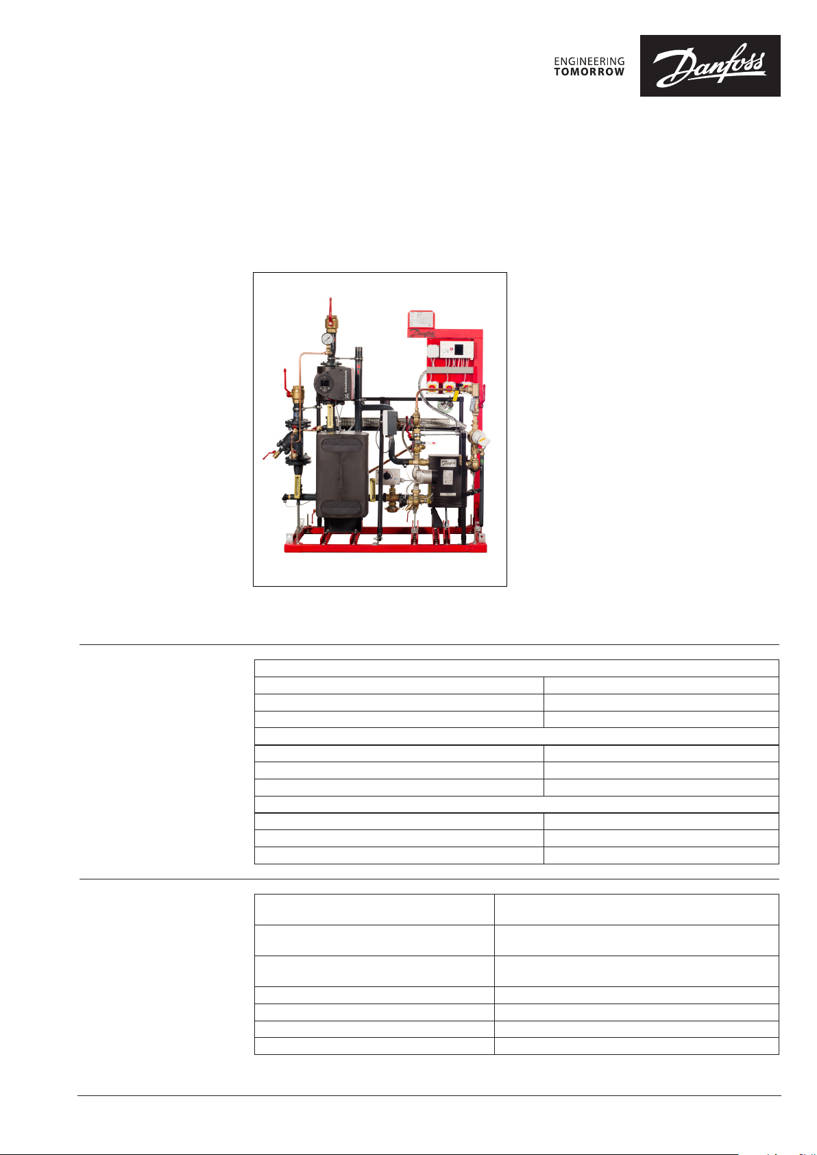
DSE FLEX – Compact Substation
General description and
application
Maximum operating
parameters
New generation subst ation is suitable for the already
proven flexible, efficient and economical infrastructure of a low carbon cit y, a District Heating net work.
Danfoss district heating substations provides the
link between dis trict heating suppliers and customer
installations. They contain all the necessary equipment to adjust the heat supplied for the needs of
the object premises as specified in the heating
supply contract. In this respect they must comply
with all applicable st andards and with the supplier’s
technical connection conditio ns. Indirect conne ctions (in which district heating and in-house systems
are hydraulically isolated) incorporate components
that separate the systems (he at exchanger), limit the
flow volume to that specified in the contract, regulate the secondary sup ply temperature and measure
energy consumption. It is a an exclusive solution
designed to optimally fulfil specific requests and
stringent requirements for district heating. By use
of the Danfoss dimensioning program you can find
out if the application you need fits DSE FLEX. The
new generation substation is designed to be floor
mounted, is keeps the robustness and friendly /
appealing outlook of the old product with the
advantage of a lighter profile, smaller size and designed for a faster and safer transport.
Primary
Maximum permissible supply temperature, primary 135°C
Maximum permissible operating pressure, primary 14, 2 bar (g)
Rated pressure, primary PN16
Secondary Heating
Maximum permissible temperature, secondary 100°C
Maximum permissible operating pressure, secondary 6 bar(g)
Minimum required pressure (static), water supply 1.0 bar(g)
Secondary Domestic Hot Water
Maximum permissible temperature, secondary 90°C
Maximum permissible operating pressure, secondary 10 bar(g)
Minimum required pressure (static), water supply 1.0 bar(g)
Materials
© Danfoss | 2018.02
Pipes, fittings, flanges, valves (primary side) P235GH, EN-JL1040 (GGC25), CuSn5Pb5Zn5-C (RG-5),
EN-GJS-400-18-LT (GGG 40.3)
Pipes, fittings, flanges, valves (heating side) P235GH, EN-JL1040 (GGC25),
EN-GJS-400-18-LT (GGG 40.3), brass (DZR type)
Pipes, fittings, flanges, valves (DHW side) 1.4301, 1.4404, brass (DZR type),
CuZn35Pb2Al-C (CC752S)
Heat exchanger 1.4404 with Cu solder
Insulation (casted parts) EPP foam, l=0.038 W/mK
Insulation (heat exchanger) PU foam, l =0.035 W/mK
Insulation (piping) PU foam, l =0.029 W/mK
VD.JV.C2.02 | 1
Data sheet DSE FLEX – Compact substation
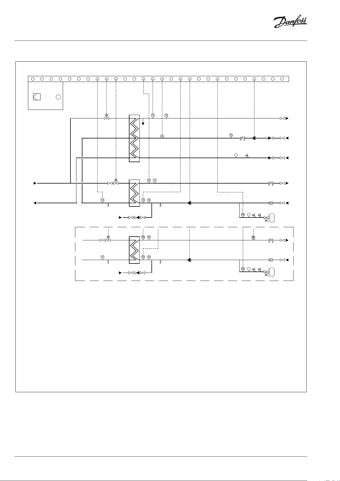
Circuit diagram
Electric box
TE
2B
750
753
95
3
445
443
A
488
474
465
430
470
472
PI
420419
468
423
411
26 Control valve HE
34 Drain valve
35 Temperature sensor
75 Ball valve
84 Drain valve
85 Thermometer
95 Control valve DHW
150, 151 Ball valve
153 Strainer
164 Balancing valve
167 Pump
171 Drain valve
174 Thermometer
175 Temperature sensor
181 Temperature sensor
175
376
365
181
174
377
364
182
171
361
167
357
164
153
813
815
PI
811
812
814
398
395
343
820
822
PI
818
819
821
430 Ball valve
443 Temperature sensor
445 Thermometer
465 Ball valve
468 Check valve
470 Pump
472 Balancing valve
474 Thermometer
488 Temperature sensor
750 Electronic controller
753 Outdoor sensor
811, 818 Pressure transmitter
812, 819 Pressure measurement
813, 814 Safety valve
815, 822 Expansion valve
150
151
PS
340
341
PS
26
1
151
35
34
720
A
75
85
84
700
A
182 Thermometer
340, 341 Ball valve
343 Strainer
357 Pump
361 Drain valve
364 Thermometer
365 Temperature sensor
376 Temperature sensor
377 Thermometer
395 Safety thermostat
398 Balancing valve
411 Ball valve
419 Pressure measurement
420 Safety valve
423 Check valve
820, 821 Safety valve
2 | © Danfoss | 2018.02
VD.JV.C2.02

Data sheet DSE FLEX – Compact substation
Function
The DSE FLEX platform can be used for various
applications such as heating, domestic hot water
and / or other water based heating system. Due
to its flexibility, it is possible to deliver a 1-, 2- or
3-circuit substation with possibility to make combinations between modules if more circuits are
required. This is based on customer requests and
the needed application(s). The construction
allows easy access to all components for maintenance and servicing purposes. Heat transfer
between the district heating network and the
building installation is achieved by way of a micro
plate heat exchanger, which ensures better heat
transfer, higher energy efficiency and reduced
pressure loss. In addition to the standard controller functions, the ECL310 offers easy remote
access via an internet page with data logging possibilities and energy optimization functions such
as weather compensation and auto-tuning (adaptive settings for domestic hot water parameters).
Dimensions
Capacity [kW] Pipe diameter External dimensions (max) Weight
Heating 1Heating
115 -4 5/
50-80
60 40 70 25 25 25 15 900 1000 1600 13 00 500 54 71 99
95 60 100 25 25 25 15 900 110 0 1600 1300 500 59 77 10 9
120 80 150 32 32 25 15 900 115 0 1700 1300 500 65 83 119
150 100 195 32 32 32 20 900 115 0 1700 1300 500 70 88 127
190 12 5 245 40 40 32 20 950 120 0 1750 1300 610 87 110 170
235 160 300 40 40 40 25 950 120 0 1750 1300 610 102 129 19 9
295 200 380 50 50 40 25 115 0 1400 19 00 1400 650 110 140 215
370 245 395 50 50 50 25 1150 140 0 190 0 1400 650 141 18 0 276
560 410 590 65 65 50 32 1200 1500 2000 150 0 650 16 4 210 322
2
115 -6 5/
60-80
70-25/
10-58
DHW
Heating 1Heating
[DN] [DN] [DN] [DN] [mm] [mm] [mm] [mm] [mm] [kg] [kg] [kg]
Cold/
warm
2
water
DHW
circulation
Length
(A1)
Length
(A2)
Length
(A3)
Height
(B)
Depth
(C)
Weight
1 circuit
Weight
2 circuits
Weight
3 circuits
These are only few examples of all the possible combinations. Depending on the customer requirements, type of heat exchangers, application, DN
combinations, etc. the dimensions may vary. Depth dimension C is considered for 2 and 3 circuit stations. Height dimension B is considered with the
electrical box in the minimum height position and the heating pump on the return line.
A1 A2 A3
B
VD.JV.C2.02
C
© Danfoss 2018.02 | 3

Data sheet DSE FLEX – Compact substation
Accessories The DSE FLEX platform is designed for Full Insu-
lation. This reduces significantly the energy loss
in the heating room.
In order to receive this accessory and also for additional details and quotations please contact the
sales responsible.
Configuration Contact the sales staff responsible for additional
details and a quotation for the DSE FLEX.
4 | © Danfoss | DHS-SMT/PL | 2018.02
VD.JV.C2.02
 Loading...