

Data sheet
Welded District Heating Stations
Type DSE-D00 (distributor module, three secondary circuits)
General description and
application:
Maximum operating
parameters
District heating transfer stations provide
the link between district heating suppliers
and customers’ systems.
They incorporate the necessary equipment
to tailor the supplied heat to the needs of the
object premises as specied in the heating
supply contract.
In this they need to comply with all applicable
standards and with the supplier’s technical
connection conditions.
Transfer modules for system separation are
described in a number of other data sheets
(see also types H0 and H0WP).
The system described here is a standard distributor
module for secondary readjusted heating circuits
Secondary
Maximum permissible supply temperature,
secondary
Maximum permissible operating pressure,
secondary
Rated pressure, secondary PN 10
Maximum permissible ow volume, secondar y VZS 25.0 m
TVS 110 °C
PZS 10 bar or depending on the safety valve
Data sheets type DSE-I1B
(primary DHW connection)
3
/h for w <= 1.2 m/s
.
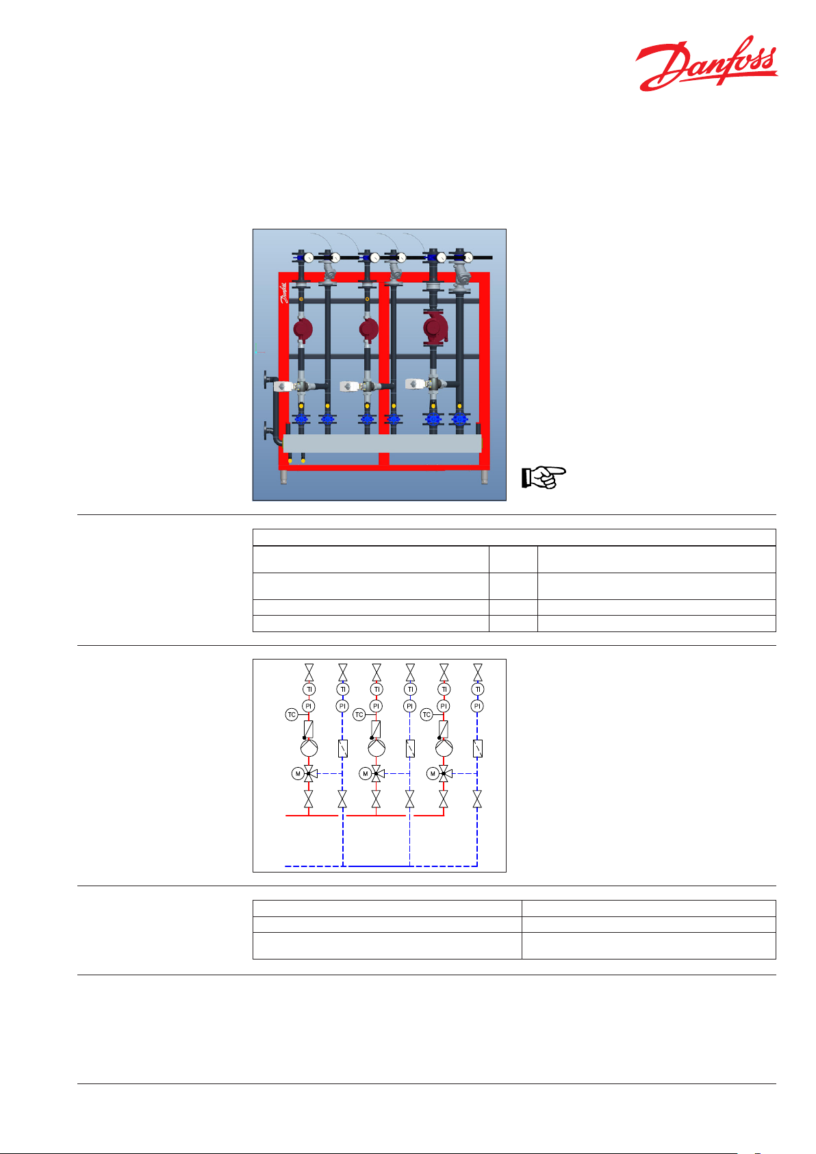
Circuit diagram: Legend
0121
0131
Materials:
Pipes and pipe ttings, anges P235GH-TC1, C22.8
0211
0411
0521
0531
0251 0252
0522
0421
0532
0450
0451
02310111
0122
0132
1211 1212
0212
0412
0422
0450
0451
02320112
0523
0533
0253
0123
0133
0213
0413
0423
0450
0451
02330113
1213
021x Shut-o device for secondary
121x Shut-o device for secondary distributor
023x Strainer
025x Non-return valve
052x/53x Supply temperature sensor
0450/451 Manometer with shut-o valve
041x/42x Thermometer with immersion sleeve
011x Circulation pump
012x/013x Mixing valve with motor
Heat exchanger 1.4404 with Cu brazing compound
Fittings CuSn5Pb5Zn5-C (RG-5), ST37.0,
EN-GJS-400-18-LT (GGG40.3)
Function:
The heated and preregulated secondary supply
water from the transfer module (e.g. H0 or H0WP)
is fed into the heating circuit distributor. The
various outputs to the attached heating circuits
For this purpose they incorporate electrical mixing
valves that ensure that the various heating circuits
receive optimal supply in accordance with the
appropriate temperature and/or timer programs.
serve to adjust the heat supplied to them
depending on their current requirements.
DEN-SMT/PL
VD.HE.G2.02 © Danfoss 06/2012
1
Data sheet Welded District Heating Stations Type DSE-D00 (distributor module, three secondary circuits)
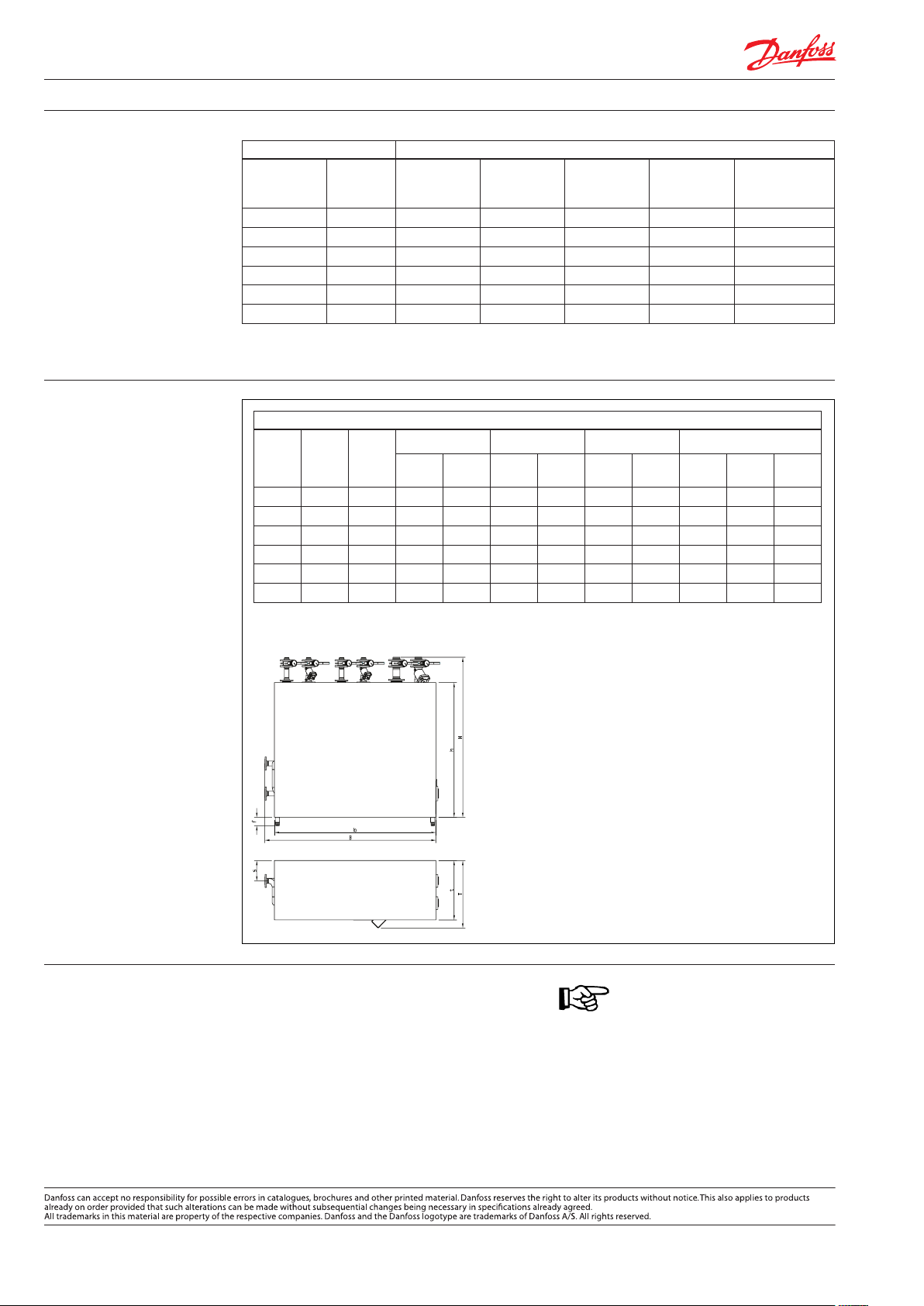
Technical data:
Dimensions:
Distributor feed Secondary (largest possible heating circuit)
max. V
DN
p
[m3/h] DN max.
max. VS
[m3/h]
Pump
MAGNA
(*)
Mixing valve
Kvs [m3/h]
delivery head
40 6.0 40 6.0 32-120 16.0 50
50 9.0 50 9.0 40-120 25.0 45
50 10.0 65 10.0 50-120 40.0 60
65 15.0 65 15.0 50-120 40.0 50
80 20.0 80 20.0 65-120 63.0 45
80 25.0 80 25.0 65-120 63.0 25
(*) other pumps on request
012x/3x VRG/AMV435 or VF3/AMV55
Dimensions
DN
In
pr.
DHW
sec.
DN
(max.)
Width Depth Height Distance
b B t T * h H p w s
40 - 40 1600 1740 550 ~ 650 1500 1645 - - 205
50 - 50 1600 1740 550 ~ 650 1500 1680 - - 215
50 - 50 1600 1855 550 ~ 700 1500 1795 - - 230
65 - 65 1600 1875 750 750 1500 1780 - - 230
80 - 80 2060 2215 750 ~ 850 1700 2025 - - 255
80 - 80 2060 2255 750 ~ 850 1700 2025 - - 255
* Dependi ng on the number of plates in the h eat exchanger
f the foot can be ad justed between: 105 … 160 mm
Residual
[kPa]
Optionally on left or right
Regulator: Data sheets ECL 110/210/310System will generally incorporate one or more
electronic heating controllers, depending on the
requirements and/or application.
Fernwärme- und Regelungstechnik · Kolumbusstraβe 14 · D-22113 Hamburg
l.: +49 (0) 40/73 67 51-0 · Fax: +49 (0) 69/8902 466 400 · info-hh@danfoss.com · www.fernwaerme.danfoss.de
2
VD.HE.G2.02
Produce d by Danfoss A/S © 06/2 012
 Loading...