

Page 1
Product Sheet
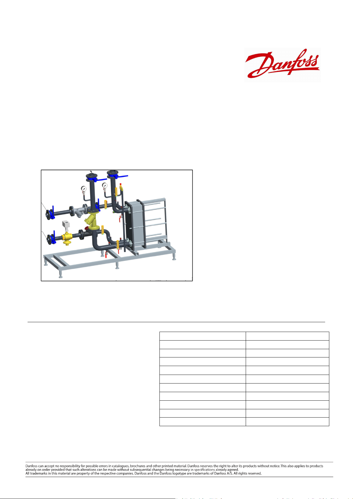
Flexible Heat Exchanger Stations
Type DSE
General description and
application
Typical Uses
• District heating building connections
• Commercial building hydronic separation
• Tall building pressure breakers
Heat exchanger stations are designed for hydronic separation of
LTHW and CHW systems. Suitable for district energy connections,
commercial buildings, and renewable applications, the stations
come complete with all relevant items to enable heat transfer,
balance, control, and service of the primary to secondary system
connection.
The stations can be installed individually, or in parallel as duty/duty
or duty /standby supplies. PN25 versions are available on request for
use as tall building or high pressure system breakers.
The stations include:
-A heat exchanger to transfer the energy between systems
-A controller which can provide individual heat exchanger control,
be linked to control multiple units, and be connected to a building
management system over-ride
-Pressure independent control valve for flow and motorised control
in a dynamic pressure system
-An MID approved ultrasonic energy meter for measurement,
monitoring, and billing accurate consumption data
-A commissioning valve for measurement of flow
-A secondary side safety valve
-Primary and secondary strainers
-Ball or butterfly isolation valves
The stations are factory tested to the pressure equipment directive
(PED)
General Operating Parameters
*other parameters are available on request
Please note, this is a generic specification and not necessarily related to your project. For exact specification, please refer to the bill of materials, and specification pages for your project.
Station Details
Station Details
Station DetailsStation Details
Pipework Sizes DN40-200
Maximum permissible supply temperature 95 ºC
PN Rating 16 Bar
Flow Rate Range 0.83 l/s to 40 l/s
Maximum Differential Pressure (Primary) 4 Bar
Safety Valve Rating (secondary) 6 Bar standard (higher upon request)
Pipes and pipe fittings, flanges P235GH-TC1, C22.8, CuS
Heat Exchanger 1.4404 with CU brazing compound
Insulation PU-Hardfoam, black, λ =0.027 W/mK
Page 2
Product Sheet Standard Heat Exchanger Stations Type DSE
LTHW ∆T
kW LTHW
Capacity
∆T
Function
The heat is drawn from the primary heat source, commonly a boiler, district heating supply, or CHP, through the
isolation valve, strainer, balancing valve, and heat exchanger, then back via the return pipe to the primary heat
source.
On the secondary side of the stations, the flow enters and passes through the isolation valve and strainer, to the
heat exchanger, where is gains energy to supply the building with heat or cooling water. A safety valve is located
on the secondary flow to ensure an excess of pressure is not experienced on the secondary system. This can be
provided with the required opening pressure.
A pressure independent control valve balances and limits flow through the pipework, to achieve the required
secondary outlet temperature. The flow control is independent of pressure fluctuations in the system and the
motorised valve element has full authority control at all load conditions.
The energy meter is positioned on the return, with two sensors, one on the flow, one on the return. The energy
meter measures the volumetric flow rate, and the difference in temperature between flow and return, to calculate
the energy used by the connection. The meter is supplied with an m-bus output to feed the energy usage to the
building management system or meter reading system
The controller senses the secondary return temperature, and modulates the control valve to achieve the desired
secondary flow temperature. An outdoor sensor can be added to provide weather compensation. A number of
applications can be provided by one controller, with an application key supplied with the station to control the
station as per the application.
The station is provided with fully isolation provided by ball or fully lugged butterfly valves, temperature and
pressure gauges, test points, and drain points.
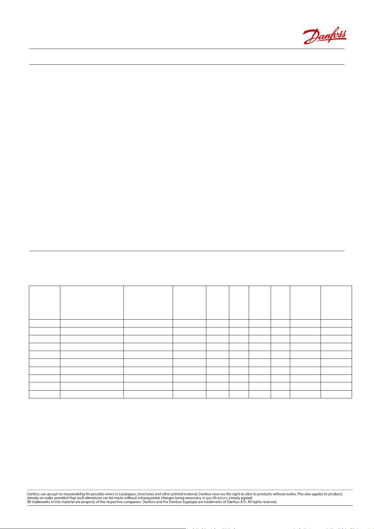
Station Flow Rate and Capacities
Capacity
Pipework Size Code Connection
DN40 DSE1 MAXI IG 40-040 1.1/2" BSP threaded 2.05 0.82 172 258 52 85 kPa 41 kPa
DN50 DSE1 MAXI IG 50-050 2" BSP threaded 3.50 1.4 294 441 88 91 kPa 45 kPa
DN65 DSE1 LARGE IT 65-65 2.1/2" PN16 Flanged 5.50 2.2 462 692 138 92 kPa 41 kPa
DN80 DSE1 LARGE IT 80-80 3" PN16 Flanged 7.50 3 629 944 189 82 kPa 39 kPa
DN100 DSE1 LARGE IT 100-100 4" PN16 Flanged 10.00 4 839 1259 252 81 kPa 39 kPa
DN125-1 DSE1 LARGE IT 125-125-15ls 5" PN16 Flanged 15.00 6 1259 1888 378 82 kPa 38 kPa
DN125-2 DSE1 LARGE IT 125-125-20ls 5" PN16 Flanged 20.75 8.3 1741 2612 522 84 kPa 41 kPa
DN125-3 DSE1 LARGE IT 125-125-25ls 5" PN16 Flanged 25.00 10 2098 3147 629 89 kPa 43 kPa
DN150 DSE1 LARGE IT 150-150 6" PN16 Flanged 30.00 12 2517 3776 755 84 kPa 40 kPa
DN200 DSE1 LARGE IT 200-200 8" PN16 Flanged 40.00 16 3357 5035 1007 80 kPa 39 kPa
Notes *1-These figures are primary duty at the max design flow rate and the ∆T described
Notes *2-These figures are at maximum capacity, with a heat exchanger selected to lose 30 kPa. If you require a lower pressure loss please discuss this
with your Danfoss representative
Max Design
Flow Rate (l/s)
Min
Design
Flow Rate
(l/s)
kW
20
(*1)
Capacity
∆T 30
(*1)
kW
CHW
(*1)
6
Max Primary
Station ∆P
(*2)
Secondary
Station ∆P
Max
(*2)
Please note, this is a generic specification and not necessarily related to your project. For exact specification, please refer to the bill of materials, and specification pages for your project.
Page 3
Product Sheet Standard Heat Exchanger Stations Type DSE
16 Bar
16 Bar
16 Bar
16 Bar
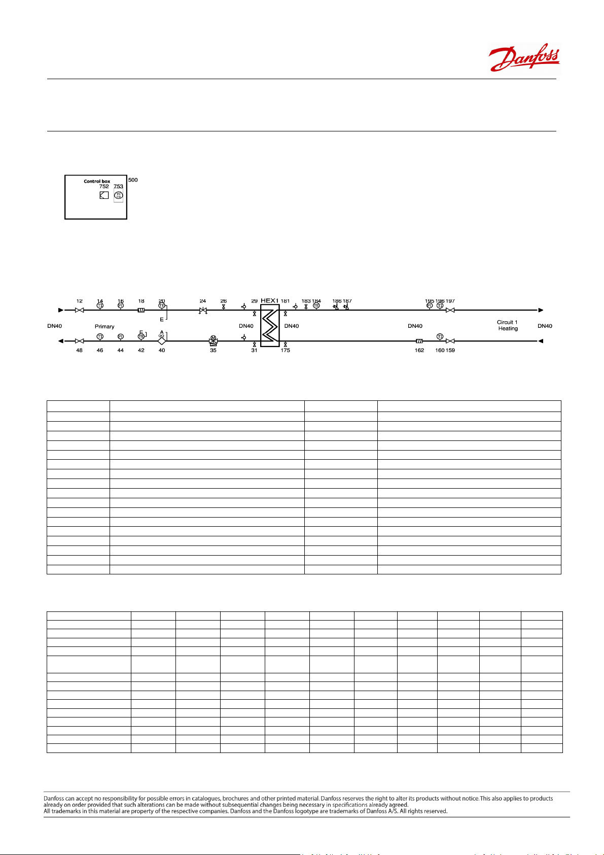
Unit Schematic
Key Components
Position Type Position Type
500 Control box 159 Isolation Valve
1 Heat exchanger 160 Pocket for thermometer sensor
12 Isolation Valve 160 Temperature Gauge
14 Temperature Gauge 175 Secondary Flow Drain Point
16 Pressure Gauge 181 Secondary Return Drain Point
18 Strainer 183 Air vent
20 Sensor for energy meter 184 Immersion Sensor
24 Hydronic Balancing valve 186 Safety valve
26 Air vent 187 Safety valve
29 Primary Flow Drain Point 195 Pressure Gauge
31 Primary Return Drain Point 196 Temperature Gauge
35 Pressure Independent Control Valve 197 Isolation Valve
40 Ultrasonic Energy meter 752 ECL controller
42 Sensor for energy meter
44 Pressure Gauge
46 Temperature Gauge
48 Isolation Valve
Component Types
Component type DN40 DN50 DN65 DN80 DN100 DN125-1 DN125-2 DN125-3 DN150 DN200
Max Flow Rate l/s 2.05 3.5 5.5 7.5 10 15 20.75 25 30 40
Heat Exchanger (See note 1) XG XG XG XG XG XG XG XG XG XG
Controller ECL 210 ECL 210 ECL 210 ECL 210 ECL 210 ECL 210 ECL 210 ECL 210 ECL 210 ECL 210
Energy Meter Sonometer 30 Sonometer 30 Sonometer 31 Sonometer 31 Sonometer 31 Sonometer 31 602 Ultraflow 602 Ultraflow 602 Ultraflow 602 Ultraflow
Pressure Independent
Control Valve
Strainers FVF FVF FVF FVF FVF FVF FVF FVF FVF FVF
Balancing Valve MSV-BD MSV-BD MSV-F2 MSV-F2 MSV-F2 MSV-F2 MSV-F2 MSV-F2 MSV-F2 MSV-F2
Temperature Sensor ESMU 100 ESMU 100 ESMU 100 ESMU 100 ESMU 100 ESMU 100 ESMU 100 ESMU 100 ESMU 100 ESMU 100
Safety Valve SYR 1915 SYR 1915 SYR 2115 SYR 2115 SYR 2115 SYR 2115 SYR 2115 SYR 2115 SYR 2115 SYR 2115
Isolation Valves IVR 954 IVR 954 VFY-LH VFY-LH VFY-LH VFY-LH VFY-LH VFY-LH VFY-LG VFY-LG
Temperature Gauges TDL 150 TDL 150 TDL 150 TDL 150 TDL 150 TDL 150 TDL 150 TDL 150 TDL 150 TDL 150
Pressure Gauges M80 0-16 Bar M80 0-16 Bar M80 0-16 Bar M80 0-16 Bar M80 0-16 Bar M80 0-16 Bar M80 0-
Air Vent Manual Manual Manual Manual Manual Manual Manual Manual Manual Manual
Drain Points IVR 954 IVR 954 IVR 954 IVR 954 IVR 954 IVR 954 IVR 954 IVR 954 IVR 954 IVR 954
Note 1-The heat exchanger selections will vary depending on duty requirement and temperature requirements
ABQM ABQM ABQM ABQM ABQM ABQM ABQM ABQM ABQM ABQM
M80 0-
M80 0-
M80 0-
Please note, this is a generic specification and not necessarily related to your project. For exact specification, please refer to the bill of materials, and specification pages for your project.
Page 4

Product Sheet Standard Heat Exchanger Stations Type DSE
Unit Components
The heat exchanger stations come skid mounted, pressure tested to PED standards, pre-wired, and ready to install. This datasheet is for standard
units which can be amended as per your requirements.
Heat Exchanger Data
Danfoss heat exchangers are specially selected to match your design application. Where
possible, Danfoss offer Micro Plate Heat Exchangers which are a revolutionary
technology, characterized by their unique plate pattern. MPHE’s enable heat to be
transferred more efficiently than any previous model of heat exchanger. The exchangers
come with specially manufactured insulation to reduce energy loss.
Technical Data:
Max working pressure: 16 Bar
Pressure Test Standard: (PED) 97/23/EC
Min Working Temperature: -10 ºC
Max Working Temperature: 150 ºC
Materials:
Plate: Stainless steel EN1.4404 (AISI316L) & EN 1.4301 (AISI 304)
Gasket Type: Glue free
Gasket Material: EPDM
Controller
Danfoss stations can be supplied complete with an in-built controller, within a specially
manufactured control panel. The panel features an ECL 210 controller and a pump
output, 3ph, for up to 2x pumps with motors 400 W-4 kW.
The ECL 210 controller, senses the temperature using the ESMU 100 temperature sensor,
and modulates the pressure independent control valve, to achieve the desired secondary
flow temperature.
The unit is supplied, pre-wired to the sensor and actuator. An ESMT outdoor sensor is
included to enable weather compensation.
The controller application is determined using an application key and will be supplied
with a key, suitable for the project application. Master/slave configurations are available.
Ultrasonic Energy Meter
An MID, ultrasonic energy meter can be provided with the station. This provides billing
accurate measurement of the energy the station uses. Accurate to +- 1%, the Sonometer
30 and 31, provide a high dynamic range of 1:100 (qi:qp) and can be used with glycol
mixtures. The meters are suitable for LTHW and CHW.
The meters come with m-bus protocol communication outputs to enable them to be
linked to an automatic meter reading or building management system
DN125+ stations come with 602 ultraflow meters.
Please note, this is a generic specification and not necessarily related to your project. For exact specification, please refer to the bill of materials, and specification pages for your project.
Page 5

Product Sheet Standard Heat Exchanger Stations Type DSE
Pressure Independent Control Valve
Danfoss AB-QM pressure independent control valves, are a world leading technology in
the world of balancing and motorised control valves. Recognised as being the ideal
solution for balance and control in variable flow systems, they feature a pressure
controller, built into a high authority control valve, to combine balancing and control into
a single valve.
Commissioning the valve is simple, with setting ring located at the valve neck, the desired
flow rate is calculated as a percentage of the valve flow capacity. This percentage is set,
and the valve commissioned in seconds
The valve is supplied with a pre-wired AMV 435 actuator, which is linked back to the
controller.
Strainer
Danfoss FVF strainers are designed for heating, district heating and cooling systems.
The strainer removes and retains foreign particles like welding beads, swarf, sand, and
any other items carried by the medium.
The strainer protects the sensitive items in the station such as the control valve, energy
meter and heat exchangers.
A ball valve can be attached to the strainer, to enable quick and simple removal of
particles from the system.
Balancing Valve
The stations can feature a manual balancing valve, for flow measurement and gives the
potential for a double regulating function.
DN40 and 50 stations feature an MSV-BD, variable orifice double regulating valve, with
360º rotating test points and an additional drain point
DN65+stations have MSV-F2 type balancing valves, with position indicator, locking
function and an integrated stroke limiter
Safety Valves
Two safety valves can be provided on the secondary flow, to ensure over-pressure on the
secondary circuit does not damage key components. The setting of the valves should be
specified at the time of order.
Isolation Valves
DN40 and DN50 stations are provided with BSP internal threaded isolation valves, type
IVR 954.
DN65-125 stations are provided with Danfoss VFY-LH manual butterfly valves. These are
fully lugged and provided with polyamid coated discs and stainless shafts
DN150-200 stations are provided with Danfoss VFY-LG gear operated, fully lugged
butterfly valves
Please note, this is a generic specification and not necessarily related to your project. For exact specification, please refer to the bill of materials, and specification pages for your project.
Page 6

Product Sheet Standard Heat Exchanger Stations Type DSE
Example Applications
Single DN65 District Heating Connection
2x DN50 Stations connected in a Duty/Standby arrangement
Page 7

Datasheet Standard Heat Exchanger Stations Type DSE
Additional Key Technical Information
Component Type DN40 DN50 D N65 DN80 D N100 DN125-1 DN125-2 DN125-3 DN150 DN200
Isolating Valve kVs
Isolating Valve Operation Hand Operated Hand Operated Hand Operated Hand Operated Hand Operated Hand Operated Hand Operated Hand Operated Gear Operated Gear Operated
Controller Supply Voltage 230V 230V 230V 230V 230V 230V 230V 230V 230V 230V
Pump Output 3ph 0.4-4.0kW 3ph 0.4-4.0kW 3ph 0.4-4.0kW 3ph 0.4-4.0kW 3ph 0.4-4.0kW 3ph 0.4-4.0kW 3ph 0.4-4.0kW 3ph 0.4-4.0kW 3ph 0.4-4.0kW 3ph 0.4-4.0kW
Temperature Gauge Range 0-120 °C 0-120 °C 0-120 °C 0-120 °C 0-120 °C 0-120 °C 0-120 °C 0-120 °C 0-120 °C 0-120 °C
Pressure Gauge Range 0-16 Bar 0-16 Bar 0-16 Bar 0-16 Bar 0-16 Bar 0-16 Bar 0-16 Bar 0-16 Bar 0-16 Bar 0-16 Bar
Balancing Valve kVs 26 40 93.4 122.3 200 304.4 304.4 304.4 400.8 685.6
Drain Point Size mm 15 15 15 15 20 25 25 25 25 25
Drain Point Flow Rate l/s @1.2
Bar ∆P
Energy Meter Nominal Flow
m3/h
Energy Meter Min Flow m3/h 0.1 0.15 0.25 0.4 0.6 0.6 1 1 1.5 1.5
Pressure Independent Control
Valve Nominal Flow m3/h
Pressure Independent Control
Valve Min Flow rate Setting
m3/h
Actuator Control Signal 3-point 3-point 3-point 3-point 3-point 3-point 3-point 3-point 3-point 3-point
Safety Valve Size 3/4" 1" 1.1/4" 1.1/4" 1.1/4" 1.1/4" 1.1/4" 1.1/4" 1.1/4" 1.1/4"
Safety Valve Max Setting 5 Bar 5 Bar 10 Bar 10 Bar 10 Bar 10 Bar 10 Bar 10 Bar 10 Bar 10 Bar
Safety Valve Capacity (each)
m3/h @ max setting
Strainer kVs 33 54 95 140 201 340 340 340 526 870
Strainer mesh size mm 0.87 0.87 0.87 1.18 1.18 1.18 1.18 1.18 1.18 1.18
6 6 6 6 13.7 18.2 18.2 18.2 18.2 18.2
10 15 25 40 60 60 100 100 150 150
7.5 12.5 20 28 38 90 90 90 145 145
3 5 8 11.2 15.2 36 36 36 58 58
3 3 15 15 15 15 15 15 15 15
Station Commissioning
The stations are supplied with minimal commissioning requirement. It is not a requirement for a Danfoss representative to commission the station. A
representative will be able to advise on the commissioning process, and it is expected that the installer will commission the station.
Full commissioning instructions are available.
Maintenance
It is necessary to check and maintain the substation on a regular basis in order to keep it in good operating condition.
A general maintenance inspection of equipment should take place at least twice per year, with a full service inspection at least once per year.
Please note, this is a generic specification and not necessarily related to your project. For exact specification, please refer to the bill of materials, and specification pages for your project.
 Loading...