

Data Sheet
DSA WALL – Wall Mounted Station
General description and
application
Maximum operating
parameters
Danfoss district heating substations provide the
link between district heating suppliers and customer installations. They contain all the necessary
equipment to adjust the heat supplied for the
needs of the object premises as specied in the
heating supply contract. In this respect they must
comply with all applicable standards and with the
supplier’s technical connec tion conditions. Indirect
connections (in which district heating and in -house
systems are hydraulically isolated) incorporate
components that separate the systems (heat
exchanger), limit the ow volume to that specied
in the contract, regulate the secondary supply temperature and measure energy consumption.
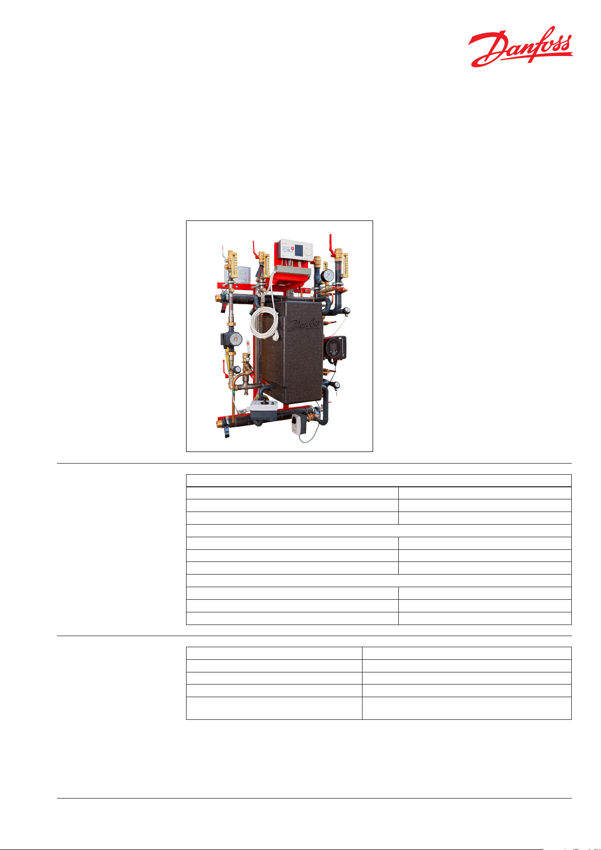
The DSA WALL is designed for use in high-parameter district heating network s. It is suitable for heating single and multifamily homes, and commercial
and industrial buildings. It oers an alternative
solution to oil or gas boilers. The DSA WALL is prepared for heating, domestic hot water and oor
heating applications. Its wall-mounted construction allows for the space saving needed for installation and servicing.
Primary
Maximum permissible supply temperature, primary 130 °C
Maximum permissible operating pressure, primary 14,4 ba r(g)
Rated pressure, primary PN16
Secondary Heating
Maximum permissible temperature, secondary 100 °C
Maximum permissible operating pressure, secondary 6 bar(g)
Minimum required pressure (static), water supply 1.0 bar(g)
Secondary Domestic Hot Water
Maximum permissible temperature, secondary 90°C
Maximum permissible operating pressure, secondary 10 bar(g)
Minimum required pressure (static), water supply 1.0 bar(g)
Materials
DEN -SMT/ PL
Pipes, ttings, anges, valves (primary side) P235GH, EN-JL 1040 (GG25), CuSn5Pb5Zn5-C (RG-5)
Pipes, ttings, anges, valves (heating side) P235GH, EN-JL 1040 (GG25), CuSn5Pb5Zn5-C (RG-5)
Pipes, ttings, anges, valves (DHW side) 1.4301, 1.4404, brass (DZR type), bronze
Heat exchanger 1.4404 with Cu solder
Insulation EPP foam λ=0.037 W/mK (heat exchanger)
PU foam λ=0.029 W/mK (primary piping)
VD.IQ.P1.02 © Danfoss 11/2014
1

Data Sheet DSA WALL – Wall Mounted Station
Circuit diagram
Electric box
TE
2B
750
M1 Combi valve
M2 Control valve
49 Drain valve
S4 Temperature sensor
380 Thermometer
387 Shut o valve
345 Supply valve
762 Pump valve
769 Thermometer
P1 Circulation pump
S6 Temperature sensor
767 Shut o valve
S3 Temperature sensor
187 Multipoint pressure measurment
191,165 Thermometer
192,164 Shut o valve
169 Strain er
P2 Heating pump
S2 Temperature sensor
175 D r ain
721 Relling valve
S1
DN20
M
M1
8
DN32 DN32
DN25
M
9
49 M2
8 Primary Supply
9 Primary Return
4 Heating Supply
5 Heating Return
2 Domestic Hot Water
1 Domestic Cold Water
3 Circulation
DHW
HE
TE
S3
175
A 721
TE
S4 380 A
TE
S2
TI
TE
S6
767
PI
187
169
P2
2
387
DN25
1
345
TI
769P1
DN20
762
TI
191 192
TI
3
4
5
165
164
Technical data
2
Typ e
HE/DHW
90 / 80
120 / 80
150 / 80
90 / 120
120 / 120
150 / 120
145 / 120
1) Reference temperatures: HE – 100/63/60/80 °C, DHW – 65/22/10/55 °C. Pressure drop: HE – 20/20 kPa, DHW – 20/20 kPa
2) Reference temperatures: HE – 100/63/60/80 °C, DHW – 65/22/10/55 °C. Pressure drop: HE – 30/15 kPa, DHW – 20/20 kPa
VD.IQ.P1.02 © Danfoss 11/2014
VM2+AMV10
1
1
1
1
1
1
2
Control valve Heat exchanger Pump
HE
DHW
AVQM+AMV30
HE DHW HE DHW
DN15/1.6 DN15/4.0/0.2 XB 37L-1-26 XB37H -1-26
DN15/ 2.5 DN15/4.0/0.2 XB 37L-1- 40 XB37H -1-26
DN15/ 2.5 DN15/4.0/0.2 XB 37L-1- 60 XB37H -1-26
DN15/1.6 DN20/6.3/0.2 XB37 L-1-2 6 XB37H-1-36
DN15/ 2.5 DN20/6.3/0.2 X B 37L-1- 40 XB37H-1-36
DN15/ 2.5 DN20/6.3/0.2 X B 37L-1- 60 XB37H-1-36
DN15/ 2.5 DN20/6.3/0.2 X B37L-1-80 XB37H-1-36
Magna 3 25-100
UPS 25-60 N
DEN -SMT/ PL

Data Sheet DSA WALL – Wall Mounted Station
Function The DSA WALL platform can be used for various
applications such as heating, domestic hot water
and / or oor heating. Due to its modular construction and exibility, it is possible to deliver
a1-, 2- or 3-circuit station based on customer
request and the needed application(s). The wallmounted construction allows easy access to all
components for maintenance and servicing purposes. Standard assembly support signicantly
reduces the time needed to place the substation
on the wall. An additional frame (accessory list)
allows for placing the substation in the centre of
the substation room.
Dimensions
Typ e
HE / DHW
DH (8 & 9) HE (4 & 5) DHW Height Width Depth
Pipe diameter
90 / 80 kW DN25 DN32 DN25 69
120 / 80 kW DN32 DN32 DN25 73
150 / 80 kW DN32 DN32 DN25 77
90 / 120 kW DN25 DN32 DN25 81
120 / 120 kW DN32 DN32 DN25 85
150 / 120 kW DN32 DN32 DN25 89
145 / 120 kW DN32 DN32 DN25 91
Heat transfer bet ween the district heating network
and the building installation is achieved by way of
a micro plate heat exchanger, which ensures better
heat transfer, higher energy eciency and reduced
pressure loss. In addition to the standard controller
functions, the ECL310 oers easy remote access via
an internet page with data logging possibilities
and energy optimisation functions such as weather
compensation and auto-tuning (adaptive settings
for domestic hot water parameters).
The primary modules allow for the upgrading of
the compact module with an additional dierential
pressure controller, measuring devices, strainers
or a heat meter to full all of the supplier’s technical connection requirements.
Weight
External dimension
[kg]
118 5 mm 800 mm 575 mm
420
446
118 5
120
208
280
575
1 2 4
8
9
3
0 40
0
246 674
800
5
8
479
820
251
9
800
120
8 Primary Supply
9 Primary Return
4 Heating Supply
5 Heating Return
2 Domestic Hot Water
1 Domestic Cold Water
3 Circulation
DEN -SMT/ PL
VD.IQ.P1.02 © Danfoss 11/2014
3

Data Sheet DSA WALL – Wall Mounted Station
Accessories Primary module may include:
- Shut-o valves
- Dierential pressure regulator
- Strainer
- Energy meter
- Temperature measurement
- Pressure measurement
Frame for stand-alone assembly, allowing for
placement of the DSA WALL in the centre of the
technical room.
Conguration The DSA WALL’s exibility of construction makes
it possible to order a substation with additional
components and dierent capacities depending
on requested features and requirements, such as:
Primary side
- Shut-o valves
- Temperature sensors
- Drain valves
Heating
- Additional temperature sensors
- Thermostat
- Pressure measurement
- Temperature maesurement
- Drain valve
Domestic hot water
- Additional temperature sensors
- Thermostat
- Pressure measurement
- Temperature measurement
- Drain valve
- Water meter
Contact the sales sta responsible for additional
details and a quotation for the DSA WALL.
4
VD.IQ.P1.02
Produce d by Danfoss A/S © 11/2014
 Loading...