

Data sheet
DSA HOME
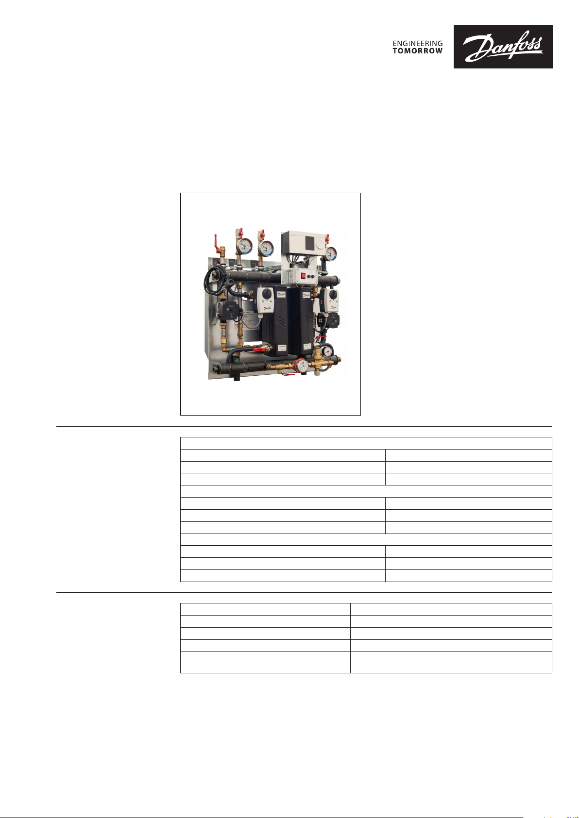
Wall Mounted Station
General description and
application
Maximum operating
parameters
Danfoss district heating substations provide the
link between district heating suppliers and customer installations. They contain all the necessary
equipment to adjust the heat supplied for the
needs of the object premises as specied in the
heating supply contract. In this respect they must
comply with all applicable standards and with
the supplier’s technical connection conditions.
Indirect connections (in which district heating
and in-house systems are hydraulically isolated)
incorporate components that separate the systems (heat exchanger), limit the ow volume to
that specied in the contract, regulate the secondary supply temperature and measure energy
consumption.
The DSA HOME is designed for use in high-parameter district heating networks. It is suitable for
heating single family houses. It is an alternative
solution to oil or gas boilers. The DSA HOME is
prepared for heating or heating and domestic
hot water applications. Its wall-mounted construction saves space needed for installation and
servicing.
Primary
Maximum permissible supply temperature, primary 130 °C
Maximum permissible operating pressure, primary 14,4 bar(g)
Rated pressure, primary PN16
Secondary Heating
Maximum permissible temperature, secondary 100°C
Maximum permissible operating pressure, secondary 6 bar(g)
Minimum required pressure (static), water supply 1.0 bar(g)
Secondary Domestic Hot Water
Maximum permissible temperature, secondary 90°C
Maximum permissible operating pressure, secondary 10 bar(g)
Minimum required pressure (static), water supply 1.0 bar(g)
Materials
© Danfoss | YYYY.MM
Pipes, ttings, anges, valves (primary side) P235GH, EN-JL 1040 (GG25), CuSn5Pb5Zn5-C (RG-5)
Pipes, ttings, anges, valves (heating side) P235GH, EN-JL 1040 (GG25), CuSn5Pb5Zn5-C (RG-5)
Pipes, ttings, anges, valves (DHW side) 1.4301, 1.4404, brass (DZR type), bronze
Heat exchanger 1.4404 with Cu solder
Insulation PU foam λ=0.035 W/mK (heat exchanger)
PU foam λ=0.0281 W/mK (primary piping)
AI00000000en-US0102 | 1
Data sheet DSA HOME - Wall Mounted Station
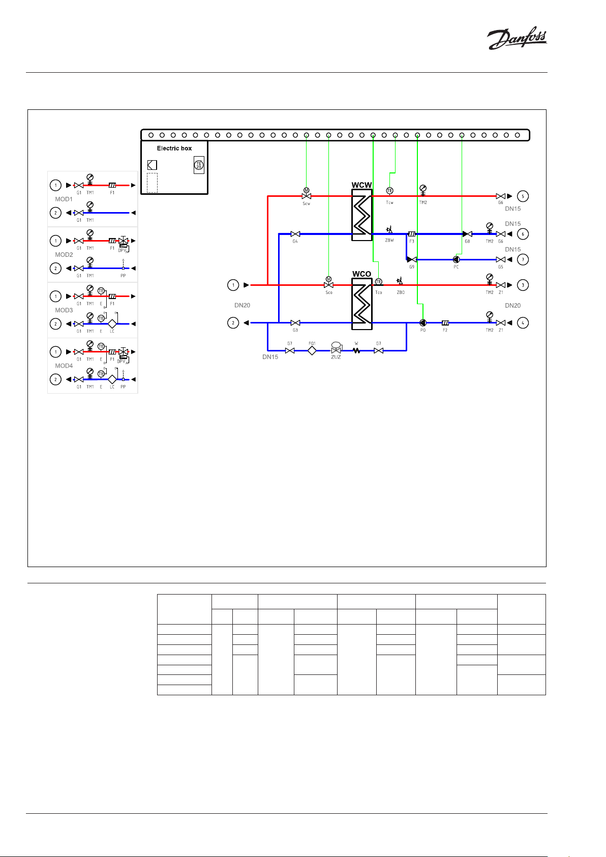
Circuit diagram
Technical data
G3, G4 Shut-o valve
Scw Control valve DHW
Sco Control valve HE
Z1 Shut-o valve
TM2 Thermomanometer
F2 Strainer
PO Heating pump
Tco Temp. sensor HE
ZBO Safety valve HE
Tcw Temp. sensor DHW
G6 Shut-o valve
G9 Check valve
ZBW Safety valve DHW
Typ e
DSA HOME 1F-1
DSA HOME 1F-2
DSA HOME 1F-3
DSA HOME 2F-1
DSA HOME 2F-2
DSA HOME 2F-3
DSA HOME 2F-4
* Maximum capacity is determined by temperature, allowable pressure drops and local regulations.
Capacity [kW]* Control valve Heat exchanger
HE
DHW HE DHW HE DHW HE DHW
–
– – – –
– – – –
40
VS 2
DN15 / 1,0
AVTQ 15 / 1,6
DN15/2,5
25
F3 Strainer
G5 Shut-o valve
G8 Check valve
PC Circulation pump
G7 Shut-o valve
FQ1 Watermeter
ZUZ Relling valve
W Elastic Hose
G1 Shut-o valve
TM1 Thermomanometer
F1 Strainer
DPV dP controller
LC Heatmeter
–
XB06L-1-16
VM 2
XB06H-1-20
–
Pump
UPM3AUTO
15-70
–
–
UPM3
DHW 15-20
Controller
ECL110
ECL310
ECL110
ECL310
2 | © Danfoss | 2017.10
VD.MG.L1.02

Data sheet DSA HOME - Wall Mounted Station
Function The DSA HOME platform can be used for various
applications such as heating or heating with
domestic hot water based on customer request
and the needed application(s). The wall-mounted
construction allows easy access to all components
for maintenance and servicing purposes. Standard
assembly accessories signicantly reduce the time
needed to place the substation on the wall.
Heat transfer between the district heating network and the building installation is achieved by
way of a micro plate heat exchanger, which
ensures better heat transfer, higher energy eciency and reduced pressure loss. In addition to
Dimensions
Typ e
DSA HOME 1F-1
DSA HOME 1F-2
DSA HOME 1F-3
DSA HOME 2F-1
DSA HOME 2F-2
DSA HOME 2F-3
Primary
DN20 DN20
Connection size
HE DHW CIR Height Width Depth
– –
– –
– –
DN15
DN15
DSA HOME 2F-4
the standard controller functions, the ECL310
oers easy remote access via an internet page
with data logging possibilities and energy optimisation functions such as weather compensation
and auto-tuning (adaptive settings for domestic
hot water parameters). For customer which are
not required advanced functionality of ECL310,
there are available DSA HOME with ECL110 which
oers basic functionality of substation.
The primary modules allow for the upgrading of
the compact module with an additional dierential pressure controller, measuring devices, strainers or a heat meter to full all of the supplier’s
technical connection requirements.
Mass
External dimensions
[kg]
24
–
810 mm
500 mm
350 mm
35 800 mm
8
max. 810
9
1
2 4 5
3
8
9
max. 350max. 800
8 Primary Supply
9 Primary Return
4 Heating Supply
5 Heating Return
2 Domestic Hot Water
1 Domestic Cold Water
3 Circulation
VD.MG.L1.02
© Danfoss | 2017.10 | 3
Danf
already on order pro
All trademarks in this material are property of the respec
Data sheet DSA HOME - Wall Mounted Station
Accessories Primary module, may include:
- Shut-o valves
- Dierential pressure regulator
- Strainer
- Energy meter
- Temperature measurement
- Pressure measurement
Sheet metal cabinet
Drain valve
Conguration The DSA HOME is a standard product, which
allows only for small modications, such as:
- changing type and kvs for primar y control valve
- changing actuator types
- changing opening pressure of safety valve
- increase volume of expansion tank
Contact the sales sta responsible for additional
details and a quotation for the DSA HOME.
oss can accept no responsibility for possible errors in catalogues, brochures and other printed material. Danfoss reserves the right to alter its products without notice. This also applies to products
vided that such alterations can be made without subsequential changes being necessary eady agreed.
4 | © Danfoss | DHS-SMT/PL | 2017.10
tive companies. Danfoss and the Danfoss logotype are trademarks of Danfoss A/S. All rights reserved.
VD.MG.L1.02
 Loading...