

Page 1

Installation and service
instructions
DHP-AT
VMGFI202
Page 2

If these instructions are not followed during installation and
service, Danfoss A/S liability according to the applicable warranty is not binding. Danfoss A/S retains the right to make
changes to components and specifications without prior notice.
© 2011 Copyright Danfoss A/S.
The English language is used for the original instructions. Other
languages are a translation of the original instructions.
(Directive 2006/42/EC)
Page 3

Contents
1 About documents and decals ..................................................... 3
1.1 Introduction .................................................................................... 3
1.2 Symbols in documents ................................................................ 3
1.3 Symbols on decals ........................................................................ 3
1.4 Terminology .................................................................................... 4
2 Important information ................................................................... 5
2.1 General safety precautions ........................................................ 5
2.2 Refrigerant ....................................................................................... 5
2.3 Electrical connection .................................................................... 6
2.4 Water quality ................................................................................... 6
2.5 Commissioning .............................................................................. 7
3 Transport, delivery check and positioning ............................. 8
3.1 Transporting heat pump ............................................................ 8
3.2 Delivery check ................................................................................ 8
3.3 Positioning the heat pump ........................................................ 8
4 The heat pump ............................................................................... 10
4.1 Dimensions and connections ................................................. 10
4.2 Components ................................................................................. 11
4.3 Principle function description ................................................ 12
4.4 Check and safety functions ..................................................... 15
4.5 Heating curves ............................................................................. 15
5 System solution .............................................................................. 17
5.1 System solution ........................................................................... 17
6 Piping installation ......................................................................... 18
6.1 Pipe connection .......................................................................... 18
6.2 Connecting cold and hot water lines .................................. 18
6.3 Connecting supply and return lines ..................................... 19
6.4 Noise and vibrations .................................................................. 19
7 Electrical installation .................................................................... 21
7.1 Connecting the operator panel ............................................. 21
7.2 Connecting circulation pump ................................................ 22
7.3 Connecting hot water tank electrical heater .................... 23
7.4 Connecting external electrical heater ................................. 24
7.5 Connecting hot water sensor ................................................. 24
7.6 Connecting buffer tank sensor .............................................. 24
7.7 Connecting reversing valve hot water ................................ 25
7.8 Connecting the power supply ............................................... 26
8 Operator panel ............................................................................... 27
8.1 Important parameters ............................................................... 27
9 Commissioning .............................................................................. 28
9.1 Checking piping installation and heating system .......... 28
9.2 Checking electrical installation .............................................. 28
9.3 Filling hot water tank and heating system and
expelling excessive air ............................................................... 28
9.4 Starting the unit .......................................................................... 28
9.5 Test Operation
............................................................................. 29
9.6 After start-up and tests ............................................................. 29
9.7 Customer information ............................................................... 30
10 Troubleshooting ............................................................................ 31
10.1 Operational problems ............................................................... 31
11 Technical data ................................................................................. 33
12 Connection diagram .................................................................... 34
13 Wiring diagram .............................................................................. 35
VMGFI202 – 1
Page 4

Page 5
1 About documents and decals
1.1 Introduction
The following information is available for this product:
•
Installation and service instructions containing information to install and commission a heat pump installation,
information about the heat pump’s function, information about accessories, technical data, troubleshooting and maintenance instructions (this document).
•
User instructions on how to operate the unit (the user manual).
1.2 Symbols in documents
The instructions contain different warning symbols, which, together with text, indicate to the user that there are
risks involved with actions to be taken.
The symbols are displayed to the left of the text and three different symbols are used to indicate the degree of
danger:
DANGER! Indicates an immediate danger that leads to fatal or serious injury if necessary measures are not
taken.
Warning! Risk of personal injury! Indicates a possible danger that can lead to fatal or serious injury if
necessary measures are not taken.
Caution! Risk of installation damage. Indicates a possible hazard that can lead to item damage if necessary
measures are not taken.
A fourth symbol is used to give practical information or tips on how to perform a procedure.
Note! Information regarding making the handling of the installation easier or a possible operational
technical disadvantage.
1.3 Symbols on decals
The following symbols can occur on decals on the different parts of the heat pump. Which symbols are used
depends on the heat pump model.
Warning symbols
!
Warning, danger!
Warning, hazardous electrical voltage!
Installation and service instructions VMGFI202 – 3
Page 6
1.4 Terminology
Term Meaning
Heating system/Heat transfer fluid
circuit
The circuit that generates heat to the property or to the domestic hot water tank heater.
Supply line The heating system’s supply line with flow direction from the heat pump to radiators/
under floor heating or domestic hot water tank heater.
Return line The heating system’s return line with flow direction from radiators/under floor heating
or domestic hot water tank heater to the heat pump.
Circulation pump Circulation pump for heating system.
Refrigerant circuit The energy carrying circuit between the outdoor air and heating system.
Refrigerant The gas/liquid that circulates in the refrigerant circuit.
Domestic hot water Domestic hot water is the water that you use around the house or office for everyday
applications, like showers, cleaning, laundry, or dishes.
Buffer tank Buffer tank is installed for equalisation of the temperature for the heating system and to
guarantee sufficient energy when defrosting.
4 – Installation and service instructions VMGFI202
Page 7
2 Important information
2.1 General safety precautions
Warning! Risk of personal injury! Children are not permitted to play with the product.
Caution! The heat pump must be installed by authorised installation engineers and the installation must
follow the applicable local rules and regulations as well as these installation instructions.
Caution! This product is not intended for persons (including children) with reduced physical, sensory or
psychological capacity, or who do not have knowledge or experience, unless supervised or they have
received instructions on how the apparatus functions from a safety qualified person.
Caution! When cooling it is important to limit the lowest flow line temperature to prevent condensation.
2.2 Refrigerant
2.2.1 Fire risk
The refrigerant is not combustible or explosive in normal conditions.
2.2.2 Toxicity
In normal use and normal conditions the refrigerant has low toxicity. However, although the toxicity of the refrigerant is low, it can cause injury (or be highly dangerous) in abnormal circumstances or where deliberately abused.
Warning! Risk of personal injury! Spaces in which heavy vapour can collect below the level of the air must
be well ventilated.
Refrigerant vapour is heavier than air and, in enclosed spaces below the level of a door for example, and in the
event of leakage, concentrations can arise with a resultant risk of suffocation due to a lack of oxygen.
Warning! Risk of personal injury! Refrigerant exposed to a naked flame creates a poisonous irritating gas.
This gas can be detected by its odour even at concentrations below its permitted levels. Evacuate the area
until it has been sufficiently ventilated.
2.2.3 Work on the refrigerant circuit
Caution! Work on the refrigerant circuit must only be carried out by a certified engineer!
Caution! When repairing the refrigerant circuit, the refrigerant must not be released from the heat pump it must be dealt with in the appropriate way.
Installation and service instructions VMGFI202 – 5
Page 8
Refilling must only be carried out using new refrigerant (for the amount and type of refrigerant see manufacturer’s
plate) through the service valves.
Caution! All warranties from Danfoss are void if, when filling with refrigerant other than Danfoss A/S
specified refrigerant, if there has not been written notification that the new refrigerant is an approved
replacement refrigerant together with other remedies.
2.2.4 Scrapping
Caution! When the heat pump is to be scrapped the refrigerant must be extracted for disposal. Local rules
and regulations related to the disposal of refrigerant must be followed.
2.3 Electrical connection
DANGER! Hazardous electrical voltage! The terminal blocks are live and can be highly dangerous due to
the risk of electric shock. All power supplies must be isolated before electrical installation is started. The
heat pump is connected internally at the factory, for this reason electrical installation consists mainly of
the connection of the power supply.
Warning! Electrical installation may only be carried out by an authorised electrician and must follow
applicable local and national regulations.
Warning! The electrical installation must be carried out using permanently routed cables. It must be
possible to isolate the power supply using a multi-pole circuit breaker with a minimum contact gap of 3
mm.
2.4 Water quality
Caution! A normal heating system always contains a certain amount of corrosion particulates (rust) and
sludge products from calcium oxide. This comes from acid that is naturally occurring in the fresh water
that the system is filled with. It is not good practice to have to fill the heating system regularly which is
why any leakage in the heating system should be repaired immediately. Normal filling should occur only
once or twice a year. The water in the heating system should be as clean as possible, always position the
dirt filter on the return line from the heating system to the heat pump, as close to the heat pump as
possible.
Caution! Hard water; Normally it is not a problem installing a heat pump in areas with hard water because
the normal operating temperature for the hot water does not exceed 60°C. In areas where there are
exceptional prevailing conditions with the water one can install a softening filter, which softens the water,
cleans any impurities and prevents the build up of calcification.
6 – Installation and service instructions VMGFI202
Page 9

2.5 Commissioning
Caution! The installation may only be commissioned if the heating system is filled and all excessive air is
expelled. Otherwise the circulation pump may be damaged.
Installation and service instructions VMGFI202 – 7
Page 10
3 Transport, delivery check and positioning
3.1 Transporting heat pump
Caution! The heat pump must always be transported and stored standing and in a dry environment. If the
heat pump is laid on the incorrect side it may become seriously damaged as the oil in the compressor can
run out in the pressure pipe and therefore prevent normal function.
Caution! Always secure the heat pump so that it cannot tip over during transportation.
3.2 Delivery check
1. Check that there is no transport damage.
2. Remove the packaging and check that the delivery contains the following components.
Table 1. Supplied contents
Quantity Name
1 Heat pump
1 Control unit with connection cord
1 Document set
1 Flexible hose for drainage of condensate water
2 1pc Buffer tank sensor, 1pc Domestic hot water tank sensor
3.3 Positioning the heat pump
3.3.1 Recommended location
When positioning the heat pump, note the following:
Caution! The heat pump must be installed outdoors and secured on a stable base, for example a cast
foundation. All four mounting points must be secured to the base.
Caution! Incorrect positioning of the heat pump risks reduction of performance.
•
Use M10 bolts for fastening the frame to the the base.
•
Select a position with good ventilation and with enough free space for installation and maintenenance.
•
Do not select a position that will block the air flow near the inlet or outlet areas.
•
No barrier allowed closer than 30 cm behind the unit.
•
Check with a spirit level that the heat pump is installed horizontally.
•
Ensure that condensated water is well drained from the unit. A flexible hose is available as accessory for drainage. If there is a freezing risk, use a heat cable inside the hose.
8 – Installation and service instructions VMGFI202
Page 11
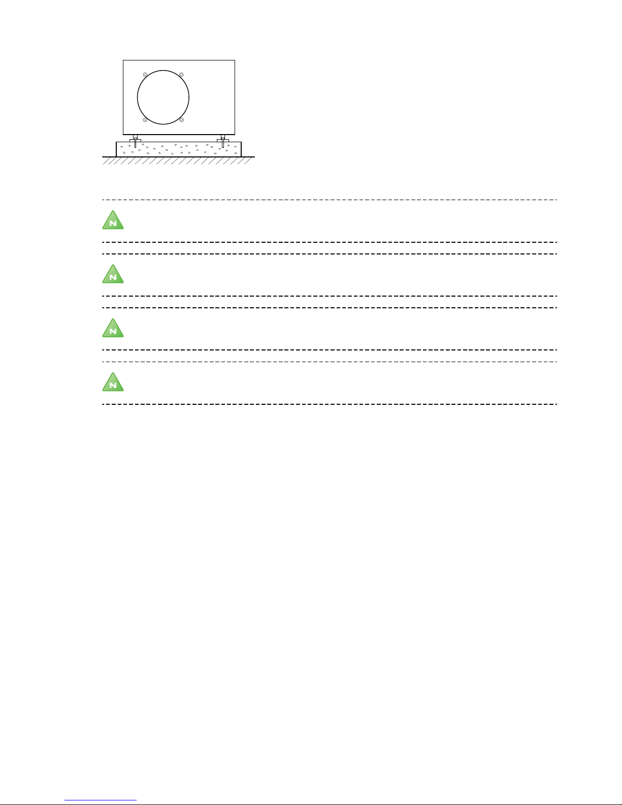
Figure 1. Positioning heat pump
Note! Avoid placing the heat pump near windows or walls to noise sensitive areas.
Note! Ensure that there is sufficient distance to neighbouring properties so that they are not exposed to
noise. Applicable local regulations must be followed.
Note! The heat pump should not be enclosed.
Note! Keep the heat pump and its immediate area free of snow, ice, leaves etc.
Installation and service instructions VMGFI202 – 9
Page 12
4 The heat pump
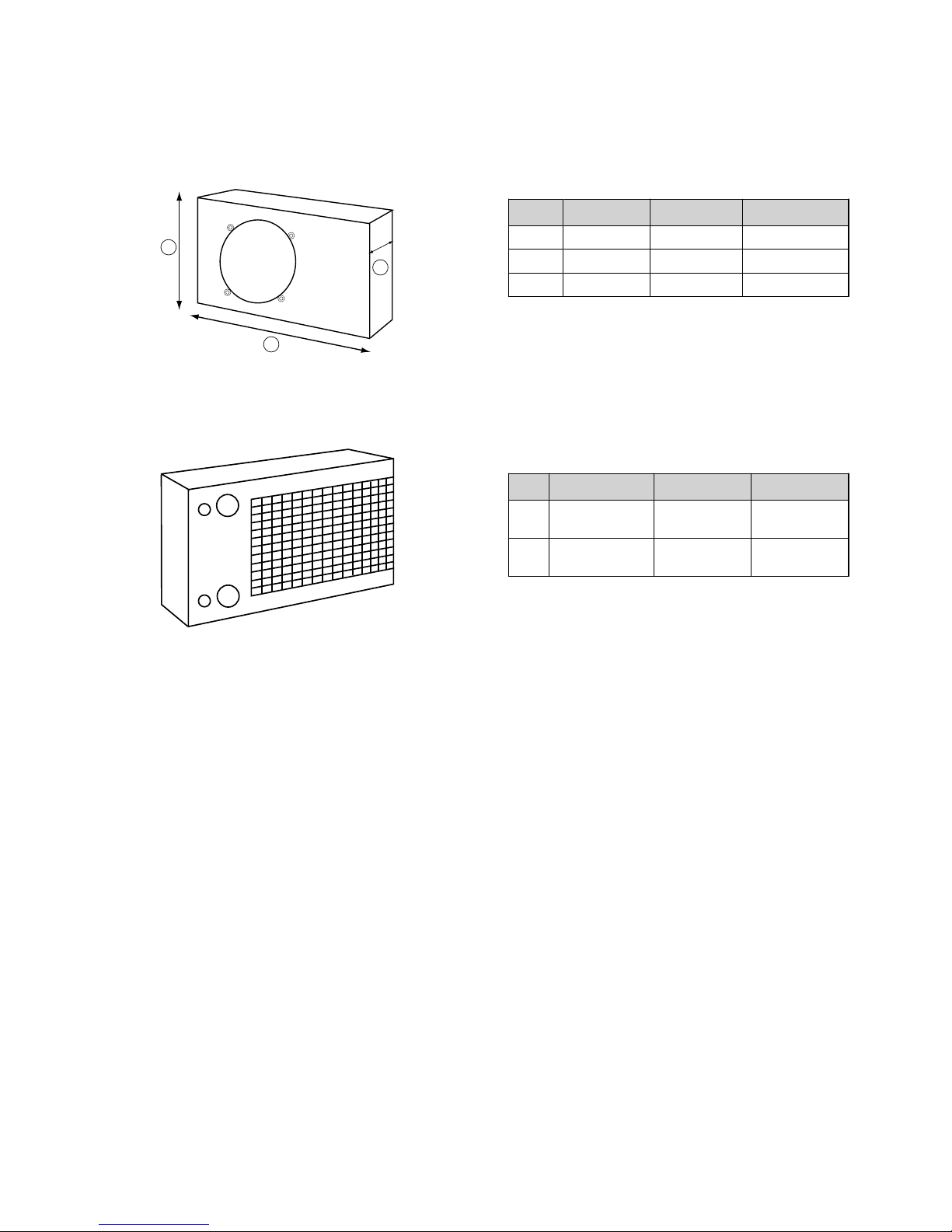
4.1 Dimensions and connections
The dimensions and connections of the heat pump is described in the pictures and tables below.
1
2
3
Figure 2. Dimensions
Pos Description 6kW 8kW
1 Height 655 mm 755 mm
2 Width 1026 mm 1026 mm
3 Deepth 495 mm 495 mm
1
2
Figure 3. Piping connections (rear side)
Pos Description 6kW 8kW
1 Supply line
pipe (red label)
DN 20
DN 25
2 Return line pipe
(blue label)
DN 20
DN 25
10 – Installation and service instructions VMGFI202
Page 13

4.2 Components
The principal components of the heat pump is shown in the picture below:
1
2
4
6
9
7
11
13
14
15
23
24
25
26
27
28
37
22
20
19
18
3
Figure 4. Components, exploded view
Position Explanation Position Explanation
1 Fan mesh/front grill 17 4-way valve
2 Fan 19 Expansion valve
3 Front panel 20 Water flow switch
4 Fan motor 22 Internal electrical heater
6 Left grill 23 High and Low pressure service ports
7 Evaporator 24 Heater exchanger
9 Electrical box, compressor capacitor, backup
heater relay, PCB, fan motor capacitor
25 Compressor
11 Top cover 26 High pressure valve
13 Rear grill 27 Pressure relief valve
14 Rear panel 28 Low pressure valve
15 Right side panel 37 Evaporator heating belt
4.2.1 Accessories
The following accessories are available for the product:
Installation and service instructions VMGFI202 – 11
Page 14

•
Hot water tank electrical heater
•
Circulation pump
•
Reversing valve hot water
4.3 Principle function description
The heat pump can provide the following main functions:
•
House heating
•
Cooling
•
Domestic Hot Water (DHW)
•
Defrostning
•
Legionella prevention
•
Frost protection
To support these functions, suitable system solutions, including external components, must be selected at installation. An example of a such system solution is shown in Figure 6. Example, system solution Page 17.
When the heat pump works in AUTO mode, DHW is prioritized. When the water tank temperature decreases too
much, the unit will switch to DHW mode until the temperature setting is reached again. The unit will then switch
back to house heating or cooling.
For more details about the default settings in the control system, see the User manual.
4.3.1 House heating
The house heating function can run in AUTO or MANUAL mode.
AUTO mode
In AUTO mode, the water temperature is adjusted by the control system according to the selected heat curve, the
desired room temperature, and the outside air temperature (if it is within the heat pump´s working range between
-15°C to +43°C). The compressor stops when the water temperature has reached the setpoint in the control system.
The heat pump has an internal electrical heater (3kW) for backup in situations where the compressor has stopped
for other reasons. According to the default settings in the control system, the internal electrical heater will start
running in the following conditions:
•
The control system discovers insufficient heating due to low outside air temperature (below -15°C).
•
The heat pump stops working as a protective measure and at the same time, the water temperature has not
reached its setpoint.
•
The heat pump is defrosting.
•
Frost protection (step 2)
In conditions with very low air temperatures and, at the same time, much hot water is required to meet the needs
of the household, an external heater is recommended. The location of this external heater has an impact on the
function and layout of the whole system solution as well as the start and stop conditions of the heat pump.
MANUAL mode
In MANUAL mode, the heat pump provides a constant water temperature according to the temperature settings in
the control system.
4.3.1.1 Start and stop conditions, internal electrical heater
The internal electrical heater will start in any of the following conditions:
•
During defrosting cycle (assuming that the parameter value in Menu 13 is set to 1= turned on).
•
During frost protection (step 2)
12 – Installation and service instructions VMGFI202
Page 15

•
During house heating:
•
o
When the air temperature is below 0°C.
o
The system requests heating operation.
o
The buffer tank temperature has decreased more than the value set in Menu 08 and 30 minutes after the
compressor has started
o
After another 90 minutes;
-
If the air temperature is still below 0°C.
-
If the system still requests heating operation.
-
If the buffer tank temperature has decreased less than the value set in Menu 08.
-
If the buffer tank temperature still has not reached the temperature measured at compressor startup.
o
During house heating operation, if the heat pump has stopped as a protection due to a failure and the
system does not reach the temperature setting, an automatic start of the internal electrical heater is triggered.
The internal electrical heater will stop in any of the following conditions:
•
If the DHW electrical heater in the water tank starts.
•
Water flow switch failure
•
Standby (and not going into frost protection, step 2)
•
Non house heating mode (for example, cooling)
•
Air temperature sensor failure
•
Buffer tank temperature sensor failure
•
Air temperature more than 0°C
•
The buffer tank temperature is higher than the temperature setting
4.3.1.2 Start and stop conditions, heating belts
When the outside temperature is low and to prevent freezing of refrigerant, heatings belts will start to work to
keep the temperatures in the heat pump withing a safe range.
4.3.1.2.1 Evaporator heating belt
The drain heater starts if all of the following conditions are fullfilled:
•
Power is on, and the operation is heating or domestic hot water
•
Compressor starts
•
The air temperature is below 1°C
The drain heater stops in any of the following conditions:
•
Non heating operation (for example, cooling)
•
Compressor has stopped for more than 30 minutes
•
The air temperature is higher than 4°C
4.3.2 Cooling
The heat pump can be set to cooling within an outside air temperature range between 8-43°C. Beyond this range
the heat pump will stop. In temperatures below 16°C, condensate problems may occur and which must be taken
care of by drainage solutions as well as isolation of water tanks and piping.
4.3.3 Domestic hot water
It is possible to produce Domestic Hot Water (DHW) by installing a heat system with a reversing valve and possibly
a hot water tank.
When the operation is house heating/DHW AUTO mode and the water temperature in the water tank decreases
more degrees than the allowed setting in the control system, the heat pump switches to produce hot water. When
the temperature reaches the setpoint again , the heat pump returns to house heating.
The maximum water temperature is 55°C. If the water temperature rises above 55°C, the heat pump will automatically go into protection mode. Considering energy saving, it is recommended to set the DHW temperature below
55°C (60°C if there is an electrical heater installed inside the hot water tank).
Installation and service instructions VMGFI202 – 13
Page 16

4.3.4 Defrosting
The heat pump has an automatic defrosting function that will start when the the ambient air temperature is low.
The heat pump will then calculate the best defrosting program depending on data collected from the temperature
sensors. As an option, defrosting can also be activated manually by the user.
Auto defrosting
The condition for auto defrosting is that the air temperature is less than 15°C and there is no failure of the coil
temperature sensor. In heating operation, when the coil temperature reaches the value set in menu 04, the defrost
starts and the compressor runs for the defrost cycle setting time in menu 03. Accumulated running time will be
cleared after the defrosting has stopped and a new cycle starts the next time defrosting is required.
Defrosting stops when the coil temp is more than the defrost stop temperature in menu 05 or when the defrost
time reaches the maximum setting specified in
menu 06.
Manual defrosting
When the air temperature is below 15°C and the compressor has run for more than 10 minutes, manual defrosting
can be activated using the key pad on the control unit The defrosting sequence will stop when the defrost time
setting or the defrost stop temperature has been reached.
The defrosting sequence is as follows:
•
Send out defrost signal and show symbol on operator panel
•
The three-way valve remains in the current position determined
by the current active operation mode.
•
Power on the 4-way valve switch.
•
Stop the fan.
•
The compressor still run.
•
The water pump runs as normal.
•
The internal electrical heater starts according to the setting in Menu 05 (if it is 0)
•
Drain heater is turned on, but controlled by its own conditions
When the defrosting stop conditions have been met, the heat pump will perform the following sequence:
•
Defrost signal ends and symbol on operator panel dissapear
•
The compressor still run
•
The fan starts.
•
After 30 seconds power off the 4-way valve switch
•
The three-way valve starts again if the domestic hot water function is active.
•
Accumulated running time of defrosting is cleared
•
The heat pump goes back to normal heating
Timer defrosting
When the air temperature is below the value set in MENU 05 and the coil temperature sensor is faulty, the heat
pump starts defrosting in intervals of 40 minutes of compressor running time.
The defrosting sequence stops after the defrosting time setting has been reached.
If the temperature sensor for the heat exchanger fails, a timer controlled defrosting cycle will start according to the
settings in the control system.
Defrosting abnormal termination
If the heat pump is switched off during the defrosting cycle, the defrosting will continue until the defrosting stop
condition has been met and then the heat pump stops.
In case of a high pressure protection situation during defrosting, defrosting stops and the heat pump shuts down
as a protection.
If there is a power failure during defrosting, when the power returns, the compressor will start testing the coil temperature after 10 minutes of operation. If the defrost conditions are met, the heat pump will start to defrost.
Note! Low pressure protection is shielded during defrosting. After the defrosting has stopped and the
normal heating operation has started again, it takes 1 minute before the low pressure switch is tested.
14 – Installation and service instructions VMGFI202
Page 17

4.3.5 Legionella prevention
There is an automatic legionella prevention when the heat pump function is set for DHW. Run at
00:00 after 7 days of operation. It will then heat up the hot water tank to 65 degrees for 15 minutes.
This is repeated once a week and kills any possible legionella bacterias in the water inside the
hot water tank.
4.3.6 Frost protection
There is an automatic frost protection function in the unit that works in two steps. When there is a risk of freezing
due to low temperatures, the unit will first start the water pump to create a water flow in the system. Next step is
to automatically start the heating operation.
•
Frost protection, step 1
When the operational status of the heat pump is Standby or powered ON, the outside ambient air temperature is
below 2°C, the return water temperature is below 8°C, the unit will automatically start operating in water pump
mode. It will exit the frost protection when the ambient air temperature is more than 3°C or the return water temperature has reached over 10°C. When this protective function is triggered, the controller will display "Err 19", but
this is not a fault. The unit will automatically recover when the conditions meet the settings in the control system.
•
Frost protection, step 2
When the return water temperature is less than 6°C, the unit will automatically start heating operation. It will exit
step 2 protection when the ambient temperature is more than 3°C or the return water temperature is more than
15°C. When this protective function is triggered, the controller will display the "Err 18", but this is not a fault. The
unit will automatically recover when the conditions meet the settings in the control system.
When the operational status of the heat pump is Standby or powered ON, the machine will start domestic hot
water function compulsorily if water tank temperature is below 13°C; then exit and return to previous status when
the water temperature is more than 16°C. The controller will display "Err 18", but this is not a fault. The unit will
automatically recover when the conditions meet the settings in the control system again.
4.4 Check and safety functions
The heat pump has a number of safety functions to protect the installation against damage during abnormal operating conditions:
•
Water flow switch protection
•
Phase sequence fault/Overcurrent protection
•
Excessive temperature difference protection of outlet and return water
•
Internal heater overheat protection
•
High pressure protection
•
Low pressure protection
•
Outlet water temperature overheat protection
•
Outlet water temperature subcooling protection
•
Exhaust gas temperature overheat protection
•
Frost protection
Depending on the condition, the heat system will stop completely or electrical heaters will start and the system
continues to work but with limited capacity. Error codes will be displayed to inform the user about the problem.
When the abnormal condition seizes, this is detected by the control system and the heat pump begins to work
according to the settings in the control system.
Electrical system
The electrical panel inside the heat pump is fused with a 5A/250V AC fuse (dimension: 5*20; model: 522).
4.5 Heating curves
The heat pump will automatically adjust the water temperature according to the following:
Installation and service instructions VMGFI202 – 15
Page 18
•
Different ambient air temperatures
•
Selected heat curve
•
Desired room temperature setting
24
25
26
27
28
29
30
31
32
33
34
35
36
37
38
39
40
41
42
43
444546474849
50
-2 0
-1 8
-1 6
-1 4-1 2-1 0- 8- 6
- 4
- 2024681012
1416
18
2022
2426
48
50
44
46
42
36
38
40
34
32
30
28
26
24
22
20
18
16
14
12
1
2
3
4
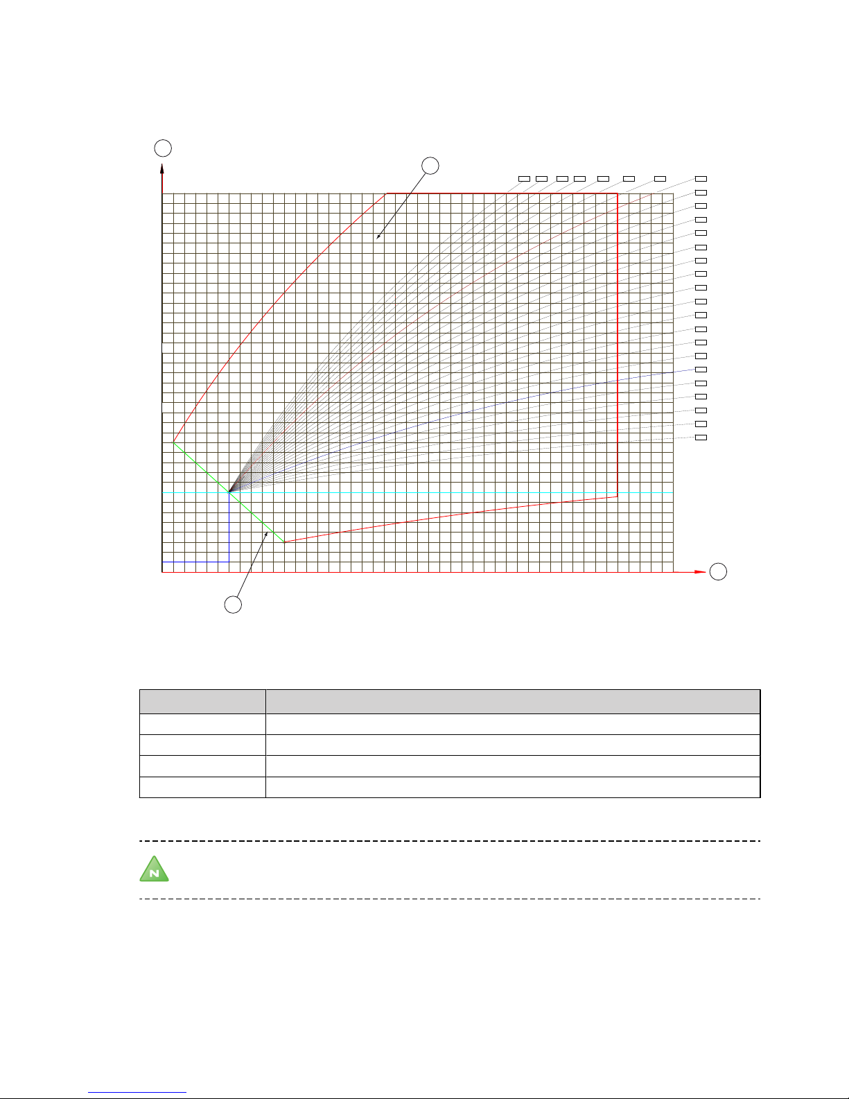
Figure 5. Heat curves and heat pump working range in AUTO mode
Position Explanation
1 Initial supply line temperature (°C)
2 Supply line water temperature (°C)
3 Working range in AUTO mode
4 Outdoor Air temperature (°C)
Note! The reference point for the heat curves is an outside air temperature of -6°C.
When the outside air temperature is -6°C, selecting heat curve 45 and AUTO mode means that the heat pump will
adjust the water temperature to 45°C. Heat curve 45 is suitable for radiator heating.
16 – Installation and service instructions VMGFI202
Page 19

5 System solution
5.1 System solution
An example of a system solution with heat pump, hot water tank, and buffer tank is shown in the picture below.
3
5
6 7
38
4
8
9
5
14
11
12
13
2
1
2
15
10
17
18
B
A
AB
16
Figure 6. Example, system solution
Position Explanation Position Explanation
1 Heat pump 10 Hot water
2 Flexible hoses 11 Temperature and pressure valve
3 Control unit 12 Temperature sensor
4 Circulation pump 13 Hot water tank electrical heater
5 Safety valve 14 Hot water tank (optional)
6 Expansion vessel 15 Buffer tank (optional)
7 Strainer 16 Temperature sensor
8 Reversing valve hot water 17 Supply line
9 Cold water 18 Return line
38 External electrical heater
Note! The illustration of the system solution is only an example and may vary between different
installations.
Installation and service instructions VMGFI202 – 17
Page 20

6 Piping installation
6.1 Pipe connection
Caution! There is a risk of the pipes to the heat pump freezing when water circulation through the heat
pump stops when outdoor temperatures fall below freezing. Normally the integrated flow sensor gives an
alarm if there is low flow (assumes that there is current to the heat pump), for example when the radiator
pump has stopped. In the event of longer flow stops, for example in case of power failure or if the plant is
OFF, there is however an obvious risk of freezing. By installing a drain plug on the inside of the house wall
it is possible to drain the part of the system that goes out to the heat pump if necessary. Another way of
ensuring against freezing is to install an intermediate exchanger indoors. In such cases one must use
glycol intended for refrigerant applications in the circuit to the heat pump unit and an extra circulation
pump, see System solution intermediate exchanger. Another option is to fill the heating system with antifreeze.
Caution! To prevent leaks, ensure that there are no stresses in the connecting pipes!
Caution! It is important that the excessive air is expelled from the heating system after installation. Bleed
valves must be installed where necessary.
Caution! Heating systems with closed expansion tanks must also be supplied with approved pressure
gauges and safety valves.
Caution! Cold and hot water pipes and overflow pipes from safety valves must be made of heat resistant
and corrosion-resistant material, e.g. copper. The safety valve overflow pipes must have an open
connection to the drain and visibly flow into this in a frost-free environment.
Caution! The connecting pipe between the expansion tank and the safety valve must slope continuously
upwards. A continuous upwards slope means that the pipe must not slope downwards from the
horizontal at any point.
Note! Ensure that the pipe installation is carried out in accordance with the dimensions and connection
diagrams.
Caution! A 6,8 bar safety valve must be installed in the system solution.
Note! It is recommended to have a circulation pump in the system solution.
6.2 Connecting cold and hot water lines
If necessary, connect the cold water (9) and hot water (10) pipes with all the necessary components to the hot
water tank, see Figure 6. Example, system solution Page 17.
18 – Installation and service instructions VMGFI202
Page 21

6.3 Connecting supply and return lines
1. Connect the supply line pipe (red label) with a flexible hose connection and with all the necessary components, see Flexible hoses, Page 19.
2. Connect the return line pipe (blue label) with a flexible hose connection and with all the necessary components including a filter.
3. Insulate the supply and return lines all the way to the heat pump.
1
2
Position Description 6 kW 8kW
1 Supply line (red) DN 20 DN 25
2 Return line (blue) DN 20 DN 25
6.4 Noise and vibrations
6.4.1 Installation of the heat pump
To prevent disturbing noise from the heat pump. the following recommendations should be observed:
•
In the event the heat pump is positioned on a vibration sensitive base, vibration dampers should be used. The
vibration dampers must be correctly dimensioned with regard to the heat pump's weight so that static spring
depression of at least 2 mm is obtained in all mounting components. Vibration dampers are available to purchase as accessories.
•
Connection of the heat transfer fluid to the heat pump must be made using a flexible hose to prevent transmission of vibration to building construction and the pipe system, see Flexible hoses, Page 19.
•
Ensure that pipes at lead-ins are not lying against the walls.
6.4.2 Flexible hoses
All pipes should be routed in such a way that vibrations cannot be transmitted from the heat pump through the
piping and continue into the building. This also applies to the expansion pipe. We recommend that flexible hoses
Installation and service instructions VMGFI202 – 19
Page 22

are used for all pipe connections to avoid the transmission of vibrations. Flexible hoses are available to purchase as
accessories. The figures below show how appropriate and inappropriate installations look using this type of hose.
20 – Installation and service instructions VMGFI202
Page 23

7 Electrical installation
DANGER! Hazardous electrical voltage! The terminal blocks are live and can be highly dangerous due to
the risk of electric shock. All power supplies must be isolated before electrical installation is started. The
heat pump is connected internally at the factory, for this reason electrical installation consists mainly of
the connection of the power supply.
Warning! Electrical installation may only be carried out by an authorised electrician and must follow
applicable local and national regulations.
Warning! The electrical installation must be carried out using permanently routed cables. It must be
possible to isolate the power supply using a multi-pole circuit breaker with a minimum contact gap of 3
mm.
The electrical installation includes connecting the following components to the heat pump:
•
Operator panel
•
Circulation pump
•
Power supply
•
Buffer tank sensor
Optional components:
•
Hot water tank electrical heater
•
External electrical heater
•
Hot water tank sensor
•
Reversing valve, hot water
For details about the connection points, see the Connection diagram, Page 1 and Wiring diagram, Page 1. For
details about the components, see Figure 6. Example, system solution Page 17.
7.1 Connecting the operator panel
Connect the communication (signalling) cable from the operator panel to the connector marked Operator panel in
the heat pump. The cable has prepared connectors that will fit only one way.
Installation and service instructions VMGFI202 – 21
Page 24

7.2 Connecting circulation pump
M
4
6 7
Connect the power cable between the circulation pump (4) and the heat pump (1) as shown
in the picture below.
22 – Installation and service instructions VMGFI202
Page 25

7.3 Connecting hot water tank electrical heater
14
13
L
N
1 2 3 4 5 6 7
Connect the power to the hot water tank electrical heater (13)
according to the picture below.
Installation and service instructions VMGFI202 – 23
Page 26

7.4 Connecting external electrical heater
A B
38
L
N
Connect the cable between the heat pump (1) and the optional external electrical heater (38).
7.5 Connecting hot water sensor
Connect the hot water tank sensor cable (12), optional, not included in delivery, to the connector in the heat
pump marked "Hot water tank sensor".
7.6 Connecting buffer tank sensor
Connect the buffer tank sensor cable (13) to the heat pump to the connector marked "Buffer tank sensor".
If a buffer tank is used, connect the other end of the sensor cable to the buffer tank. If the system solution is with-
out a buffer tank, attach the sensor to the supply line.
24 – Installation and service instructions VMGFI202
Page 27

7.7 Connecting reversing valve hot water
Connect the cable to the reversing valve, hot water (8), according to the picture.
M
8
1 2 3 4 5 6 7
Installation and service instructions VMGFI202 – 25
Page 28

7.8 Connecting the power supply
Warning! Follow local and national rules and regulations for the specification of the power cable.
L N
1
0
Connect the power cable between the multi-pole circuit
breaker and the heat pump (1).
The picture below shows alternative connections.
1 2
L
N
1 2
3 4
L
N
Figure 7. Connection alternatives
26 – Installation and service instructions VMGFI202
Page 29

8 Operator panel
The heat system is controlled by an operator panel with a display that shows operational information
A keypad is used for user interaction, that is selecting functions, navigating the menu system, and for parameter settings. When the heat pump is turned on, the display shows the operational mode and the water temperatures. The default settings are house heating/dhw in AUTO mode. For more information about the operator panel,
see the user manual.
1
2
3
4
CC
Figure 8. Layout of operator panel
Position Explanation
1 Display
2 Indicator
3 Power button
4 Keypad
8.1 Important parameters
•
Curve
•
Room
•
Adjust heat curve
•
Temperatures
•
Cooling
Installation and service instructions VMGFI202 – 27
Page 30

9 Commissioning
Note! Read the safety instructions!
Before filling water in the heating system or turning on the power, the installation must be checked for safety
and functional capability.
9.1 Checking piping installation and heating system
Pipe connections in accordance with the system solution.
•
Flexible hoses on the supply and return lines
•
Pipe insulation
•
Strainer on return line
•
All excessive air has been expelled from the heating system
•
All radiator valves fully open
•
Expansion tank heating system (not included in the delivery)
•
Safety valve for expansion tank
•
Filler valve with non-return valve heating system (not included in the delivery)
•
Safety valve for cold water (not included in the delivery)
•
If an external domestic hot water heater is installed, also check:
o
Exchange valve
o
Bleed valve (not included in the delivery)
9.2 Checking electrical installation
•
Circuit-breaker (not included in the delivery)
•
Fuse protection
•
Positioning of the outdoor sensor
•
Communication cable between heat pump and operator panel/control unit.
9.3 Filling hot water tank and heating system and expelling excessive air
1. Fill the water heater/hot water tank with cold water by opening the filler valve that is on the valve pipe.
2.
Expell all excessive air by opening one of the hot water taps.
3. Then fill the water heater coil and the heating system with water through the filling valve to a pressure of
approximately 1 bar.
4. Open all radiator valves fully.
5. Expell all excessive air from the radiators.
6.
Refill the heating system to a pressure of approximately 1 bar.
7. Repeat the procedure until all air has been expelled.
8. Check the system for leakage.
9. Leave the radiator valves fully open.
9.4 Starting the unit
1. Ensure that the main circuit breaker is on.
2.
Press
on the keypad.
The displays shows the current status of the heat system.
After the power has been turned on to the heat pump, the system starts in house heating/DHW AUTO mode with a
desired room temperature as set in MENU 02 (see the default settings in the user manual).
28 – Installation and service instructions VMGFI202
Page 31

9.5 Test Operation
Caution! The installation may only be commissioned if the heating system and water heater have been
filled and excessive air expelled from the pipes. Otherwise the circulation pump can be damaged.
Caution! Any alarms that may occur in connection with the installation must be fault-traced.
Test operate and, at the same time, check the following functions of the components in the heat system:
•
Flows and actuators
•
Circulation pump is running
•
Compressor is running
•
Reversing valve hot water switches from house heating/cooling to DHW
•
External electrical heater starts as required
•
Hot water tank electrical heater starts as required
•
Fan
•
Internal electrical heater starts as required
9.6 After start-up and tests
Note! Remember that it takes time for the heat pump to heat a cold house. It is best to let the heat pump
work at its own pace and NOT raise or alter any values in the control system to try to heat it up more
rapidly.
Caution! If there is an alarm in conjunction with installation it usually means that there is air in the system.
Caution! In the event of longer periods of downtime and risk of ice build-up in the system, the heat pump
must be drained of water.
9.6.1 Adaptation to the heating system
If the circulation pump is used with a fixed pump speed the heat pump settings must be adjusted to the applicable heating system, for instance an underfloor heating or radiator system. The delta temperature (the difference
between the supply line and return line) should be 7–10°C. If this is not reached, the flow of the circulation pump
may need adjusting depending on the applicable heating system.
9.6.2 Change operating mode
How to change the operating mode and other parameter values is described in the User manual.
9.6.3 Noise check
During transportation and installation there is a certain risk that the heat pump can be damaged, components
may move or get bent and this can cause noise. Because of this it is important to check the heat pump when it has
been installed and is ready to be commissioned to ensure that everything is in order. Test operate the heat pump
in both heating and hot water modes to ensure that there is no abnormal noise. While doing this, check that there
is no abnormal noise in other parts of the house because unwanted noise can occur in rooms other than the one
where the heat pump is located.
Noise is produced from the heat pump when the fan is in operation, check during manual operation that there is
no disturbance in your own home as well as none caused to any neighbours.
Installation and service instructions VMGFI202 – 29
Page 32

9.6.4 Trimming the heating system
To obtain a heating system balance and obtain an even and comfortable indoor temperature, the heating system
must be adjusted according to the example below.
Note! Adjust the heating system during the winter to obtain the greatest possible output.
Note! Trimming must be carried out over a few days as the inertia in the heating system causes the indoor
temperature to change slowly.
1. Choose one of the house’s rooms as a reference room for the indoor temperature, where the highest tem-
perature is required, 20-21°C.
2. Place a thermometer in the room.
3. Open all the heating system’s radiator valves fully.
4. Leave the heat pump’s room temperature setting at 20°C.
5. Note the temperature in the reference room at different points in time over a 24 hour period.
6. Adjust the room temperature so that the reference room reaches your required indoor temperature of
20-21°C. Remember that other rooms will have different temperatures during trimming, but these are
adjusted later.
7. When the reference room has an even temperature of 20 - 21°C over a 24 hour period, you can adjust the
radiator valves in the other rooms so that their indoor temperatures are the same temperature or lower
than the reference room.
9.7
Customer information
After installation and test operation, the customer must be informed about their new heat pump installation. It is
important that the customer understands the behaviour of the heatpump and the result of any changes made to
the default settings in the control system. See the checklist in the installation protocol (in the user manual) regarding the information that the installer must give the customer.
Note! The serial number must always be given for warranty matters. The serial number is found on the
exterior of the heat pump cabinet.
30 – Installation and service instructions VMGFI202
Page 33

10 Troubleshooting
10.1 Operational problems
Operational problems can be solved by troubleshooting the following areas:
•
Alarms
•
Leakage (fluid side)
•
Abnormal noise in the heat pump or radiator system
•
Hot water
•
Heating
•
Other issues
There may be more than one way of troubleshooting a cause.
10.1.1 Alarms
Error
code
Description
00 Communication failure
01 Return water sensor (T9) failure
02 Supply water sensor (T8) failure
03 Water flow switch protection
04 Phase sequence error (only applies to 3-phase models)
05 Excessive temperature difference protection of supply and return water
06 Internal heater overheat protection
07 Condenser overheat protection
08 Hot water tank sensor (T3) failure
09 Buffer tank sensor (T2) failure
10 High pressure
11 Low pressure
12 Supply water temperature too high
13 Supply water temperature too low
14 Return gas temperature sensor (T5) failure
15 Exhaust gas temperature sensor (T4) failure
16 Exhaust gas temperature overheat protection
17 Null
18 Frost protection, step 2 (non-fault)
19 Frost protection, step 1 (non-fault)
20 Air temperature sensor (T1) failure
21 Heating coil sensor (T7) failure
22 Cooling coil sensor (T6) failure
23 Exceeded operation range warning (non-fault)
Installation and service instructions VMGFI202 – 31
Page 34

10.1.2 Temperature sensor locations
The location of the internal temperature sensors are shown in the principal diagram below:
T7
T8
T1
T4
T5
1
Figure 9. Sensor locations
Sensor Description
T1 Air temperature
T2 Buffer tank, see System solution, Page 1.
T3 Hot water tank, see System solution, Page 1.
T4 Exhaust gas temperature
T5 Return gas temperature
T6 Cooling coil (external sensor)
T7 Heating coil
T8 Outlet water (supply line)
T9 Inlet water (return line)
Position Explanation
1 PCB
•
32 – Installation and service instructions VMGFI202
T9
T6
Page 35

11 Technical data
Installation and service instructions VMGFI202 – 33
Page 36

12 Connection diagram
34 – Installation and service instructions VMGFI202
Page 37

13 Wiring diagram
Installation and service instructions VMGFI202 – 35
Page 38

VMGFI202
 Loading...