

Page 1
Installation Instructions
DEVI EasyConnect
Heating Cable Connection System
IP 68
10
20
30
40
50
60
mm
0
Standards:
DIN VDE 0606 T200, DIN EN 61984 (VDE 0627), VDE 0110 IEC 60999;
CSA: C22.2 N. 182.2-M1987; LR Type Approval System
DEVI EasyConnect enables you to modify your heat tracing circuit in 1 click.
You can use the EasyConnect indoors as well as outdoors. The connectors are
IP 68 rated by VDE and CE marked. This 3 pole Connector is rated for 240 Volt
and 20 Amps and can be used within a temperature range of -40° to 100°C.
These Installation Instructions will give you details about connecting the product
to power and heat tracing cables as well as a few design tips.
WARNINGS
70
80
90
100
11 0
120
130
140
150
160
To prevent electrical shock, short-circuit or sparks please read the •
installation manual of the connector and the heat tracing cable carefully
before installation.
Connect EasyConnect to the heat tracing cable and power cable only with •
the power switched off.
Do not use this connector without using an earth leakage circuit breaker.•
Do not connect the two bus wires of the heat tracing cable together. This •
will cause a short circuit.
Use for end termination the ECF with end cap or an ETK, • do not leave the
end of the heat tracer unterminated.
Avoid contact with water during the installation of the EasyConnect.•
Avoid contact with water during the installation of the heat tracing cable.•
Make sure that the connection is not immersed in water after installation.•
Use only 2,5 square non stranded power cable for the power connector.•
Page 2
DEVI® EasyConnect INSTALLATION PROCEDURES
The following installation procedures are suggested guidelines for
the installation of DEVI EasyConnect Kits.
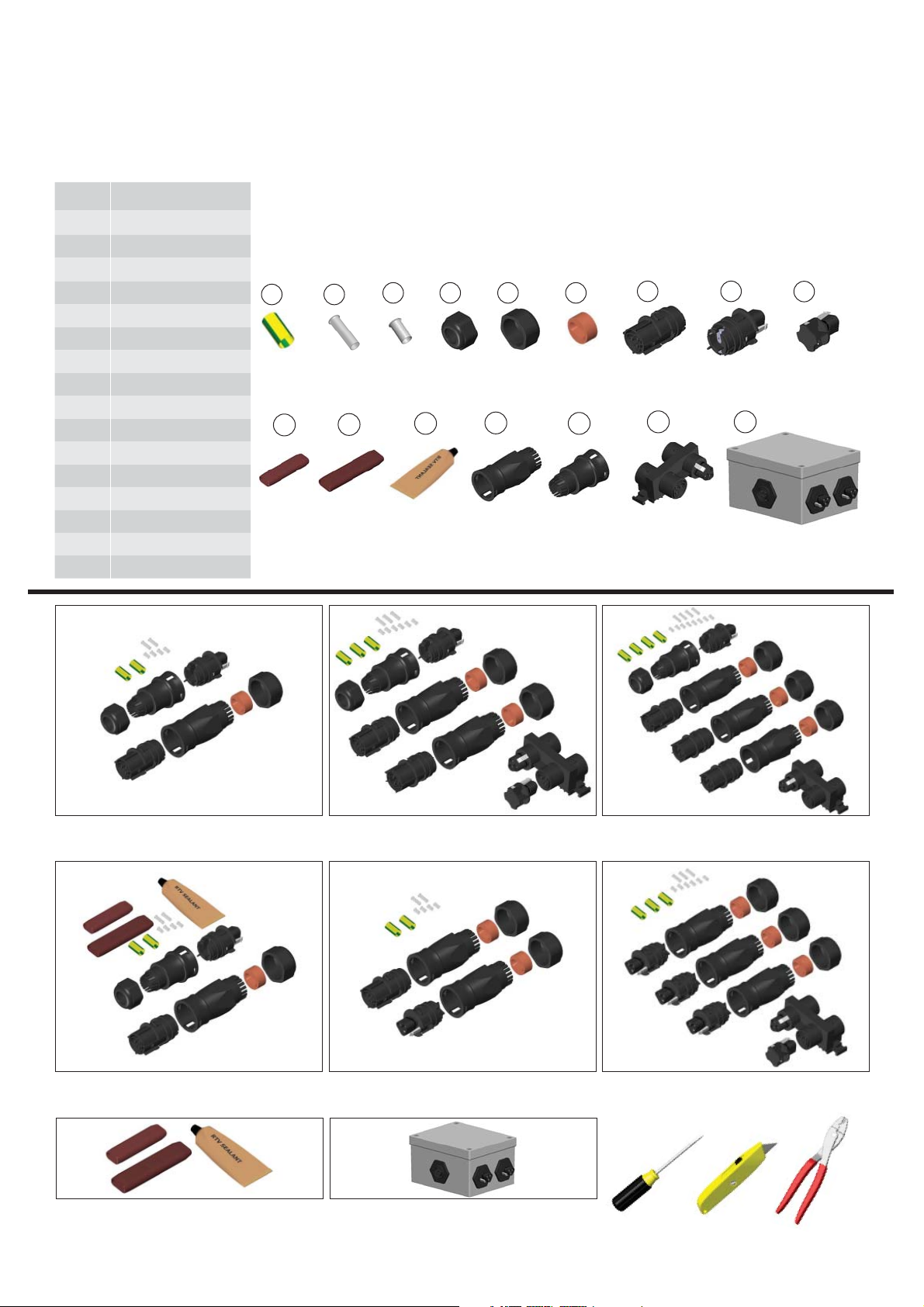
Contents Overview:
Item Description
1 Ground Sleeve
2 Large Crimp
3 Small Crimp
4 ECF Compression Nut
5 ECM Compression Nut
6 Cable Gland
7 Female Connector
8 Male Connector
9 ECEM
10 ET-6 End Cap
11 ET-60 Over End Cap
12 RTV Sealant
13 ECM
14 ECF
15 ECS
16 EC-JB4
1
10
2
11
3 4 5
12
13
6
14
7 8
15
16
NOTE: Items shown above are a comprehensive overview of DEVI EasyConnect fi ttings.
Refer to individual kits below for items included.
9
EC-1 Kit Contents EC-2 Kit Contents EC-3 Kit Contents
EC-1 + ETK Kit Contents EC-T1 Kit Contents EC-T2 Kit Contents
Tools Required . . .
EC-ETK Kit Contents EC-JB 4 Kit Contents
2
Page 3

DEVI® EasyConnect INSTALLATION PROCEDURES
Heating Cable Fabrication...
Heating Cable
Cable Gland
Remove ECM
Compression Nut
ECM
Grommet
1. Slide the ECM compression nut over the cable. Slide
the cable gland over the cable with the small opening
facing the compression nut. Remove the black ECM
grommet and discard. Slide ECM on to the cable.
10 mm
30 mm
2. Remove 30mm of the outer jacket. Do not cut the
ground braid under the outer insulation jacket.
Do not cut or damage the
ground braid.
Conductive Matrix
15 mm
Ground Braid
3. Pull back the ground braid to allow for further
fabrication.
12 mm
4. Remove 10mm of the exposed cable.
Crimps
7. Slide a small crimp over the exposed bus wires.
Crimp towards the inner edge to hold in place.
Use caution to not deform the outer end of the
bus wire crimps as they will need to fi t into the
electrical terminals.
5. Remove 15mm of the primary insulation jacket to
expose the conductive matrix.
Male Connector
8. Insert the crimped bus wires into the designated
male connector terminals (L and N) and fasten
tightly. Make sure the connector is aligned
properly with the ECM latch holes. Rotate the
connector if alignment is needed. The crimp
will fl atten as the terminal screw is tightened. To
prevent arcing, make sure all wire strands are
securely fastened.
6. Remove 12mm of the conductive matrix. Start by
skiving the sides of the matrix to expose the bus
wires. Pull bus wires from matrix. Remove matrix
carefully. Do not cut bus wire strands.
Do not cut or damage the bus
wire strands.
Ground Braid
9. Twist the ground braid to form a single strand.
Make sure the strand is located on the same
side of the ground terminal to allow for suffi cient
length to be inserted into the terminal.
3
Page 4

DEVI® EasyConnect INSTALLATION PROCEDURES
Heating Cable Fabrication Continued....
Large Crimp
Ground Sleeve
10. Slide a large crimp over the twisted ground braid.
Crimp towards the inner edge to hold in place.
Slide the ground sleeve over the crimped ground
strand.
11. Insert the crimped and sleeved ground braid into
the designated terminal. Tighten until the terminal
screw bottoms out. The crimp will fl atten as the
terminal screw is tightened. To prevent arcing,
make sure all wire strands are securely fastened.
End Termination Fabrication...
Heating Cable
1. Apply a liberal amount of RTV Sealant to the end
of the heating cable.
2. Apply a liberal amount of RTV Sealant to the inside
of the ET-6 end cap.
12. Slide the ECM toward the connector and connect
making sure the latches click into position. Slide
the compression nut forward and engage the
threads. Tighten securely.
ET-6 End Cap
3. Slide the ET-6 end cap over the end of the heating
cable.
ET-6
End Cap
ET-60
Over End Cap
4. Apply a liberal amount of RTV Sealant to the outside
of the ET-6 end cap. Slide the ET-60 end cap over
the end of the ET-6 end cap.
4
Page 5

DEVI® EasyConnect INSTALLATION PROCEDURES
Power Cable Fabrication...
Power Cable
Power Wires
ECF
Compression Nut
1. Slide the ECF compression nut and ECF onto the
power cable. Proper orientation is required to
allow for assembly after electrical connections
are made.
Large Crimp
Ground Sleeve
Crimps
15 mm
2. Remove 15mm of the outer jacket. Do not cut the
power wires under the outer insulation jacket.
Do not cut or damage the power wires.
Female Connector
9 mm
3. Remove 9mm of the power wire insulation.
Do not cut or damage the wire strands.
4. Slide small crimps over the exposed black and
white wires and a large crimp over the green
ground wire. Crimp towards the inner edge to
hold in place. Use caution to not deform the
outer end of the wire crimps as they will need
to fi t into the electrical terminals.
5. Insert the crimped power wires into the designated
female connector terminals (L and N) and fasten
tightly. Make sure the connector is aligned properly
with the ECF latch holes. Rotate the connector if
alignment is needed. The crimp will fl atten as the
terminal screw is tightened. To prevent arcing, make
sure all wire strands are securely fastened.
6. Slide the ECF toward the connector and connect
making sure the latches click into position. Slide the
compression nut forward and engage the threads.
Tighten securely. Connect the ECM to the ECF.
Make sure the latches click into position.
Do not separate when energized.
5
Page 6

Kit Confi gurations:
Model: EC-1
Heat Tracer
ECM
ECF
Power Cable
Snap in Place
Power To Heat Tracer Connection Kit
(ART. NO. 98300870)
Model: EC-3
ECS
ECM
ECF
Power Cable
Heat Tracer
Snap in Place
Power To (3) Heat Tracers Connection Kit
(ART. NO. 98300876)
Model: EC-2
ECS
ECEM
Power Cable
ECF
Heat Tracer
ECM
Snap in Place
Power To (2) Heat Tracers Connection Kit
(ART. NO. 98300875)
Model: EC-1 + ETK
ET-60
Over End Cap
ECM
ECF
Heat Tracer
Snap in Place
Power Cable
Power To Heat Tracer With End Termination Kit
(ART. NO. 98300873)
Model: EC-T1
Heat Tracer
ECM
ECM
Snap in Place
Heat Tracer
Heat Tracer To Heat Tracer Connection Kit
(ART. NO. 98300871)
Model: EC-ETK
ET-60
Over End Cap
Heat Tracer
End Termination Kit
(ART. NO. 98300872)
Model: EC-T2
ECM
ECS
ECEM
ECEM
ECM
Heat Tracer
Heat Tracer
ECM
ECS
ECM
Heat Tracer To (2) Heat Tracers Connection Kit
(ART. NO. 98300874)
Model: EC-JB4
Junction Box Power to (4) Heat Tracers Kit
(ART. NO. 98300877)
Specifi cations and information are subject to change without notice. Form: CPD1075-1211
 Loading...