

Page 1
Service Kit Instructions
]
Control Valves
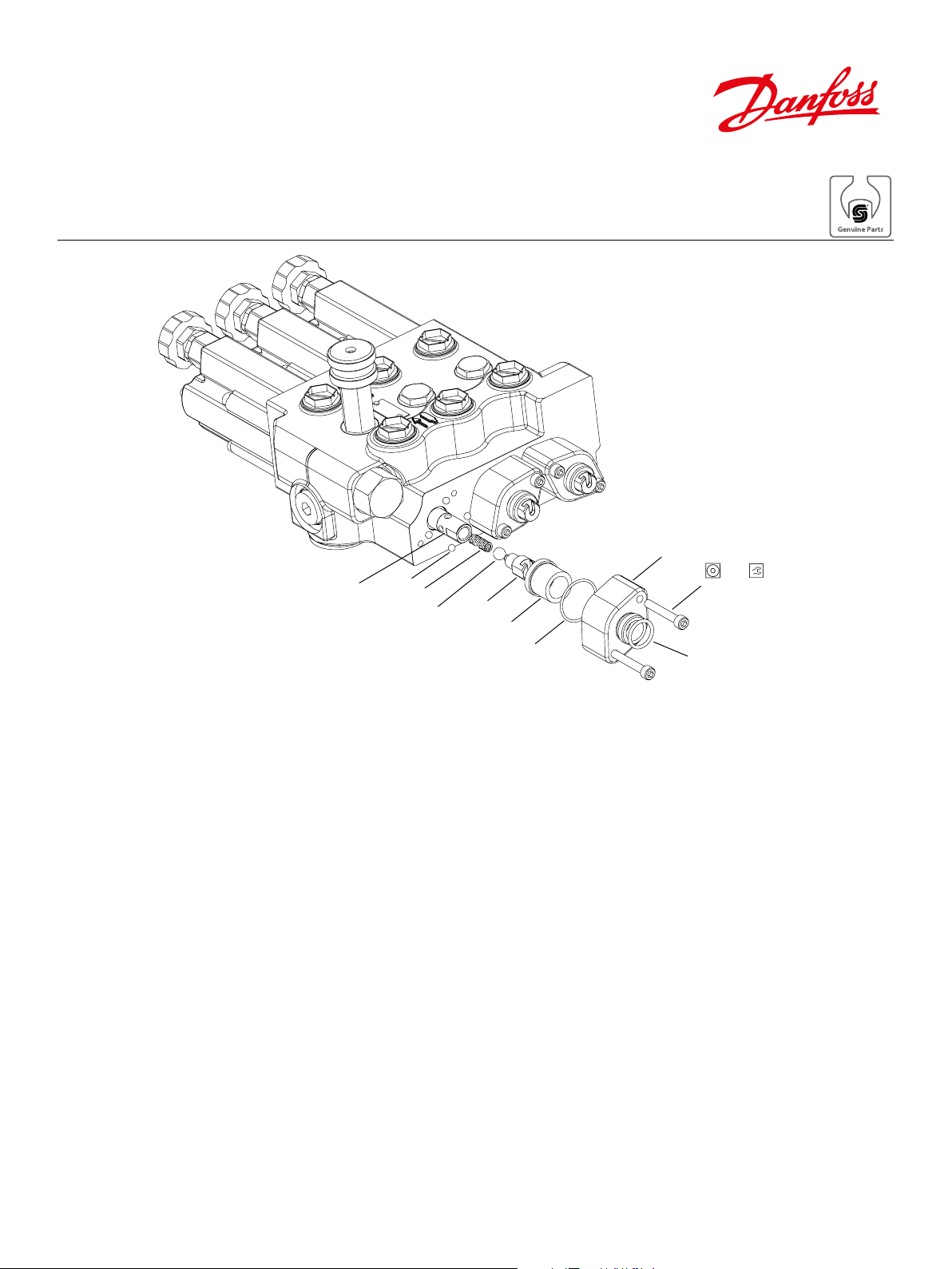
Detent float deluxe rear replacement procedure
Spool
0009
0002
0011
0006
0007
0004
0008
0003
0005
5 mm
12-14 N•m
[9-11 lbf•ft
Disassembly instructions
Assembly instructions
1. Clean valve to remove debris and avoid contamination.
2. Remove end cap screws (0005) using a 5 mm internal hex wrench.
3. On the clevis end adaptor (0006) and the main spool there are two 0,562” ats for
unscrewing this joint. Remove the clevis end adaptor (0006).
4. After disassembling the clevis end adaptor (0006) from the spool, remove the detent sleeve
(0007), steel balls (0009 and 0011) and the detent spring (0002) from the spool.
5. Thoroughly clean and dry all parts which are to be reassembled using a suitable solvent,
making sure to remove the old lubricant.
1. Apply a generous amount of grease to the detent spring (0002) and insert into spool end.
2. Insert large ball (0011) into spool end.
3. Apply generous amount of grease to small detent balls (0009), insert one detent ball into
each hole located on the outside of the spool.
4. To assemble the detent sleeve over the spool, push in the large steel ball (0011) until it is
past the center line of the small detent balls (0009). Slide the detent sleeve (0007) over the
detent balls (0009), for a total of four balls.
5. Insert the clevis end adaptor (0006) into the spool end and torque to 19 - 22 ft/lbs.
6. Lubricate and install the two o-rings (0004 and 0003) onto the end cap (0008). Place the
end cap (0008) over the sleeve assembly (0007) and align the mounting holes with those of
the valve body. Install mounting screws (0005). Liquid lock threads per ES-22-A and torque
9 - 11 ft./lbs.
© Danfoss, 2016 AN00000345en-US | 11183187• Rev 0101• August 2016 1
 Loading...