


User guide for Coolselector®2. Not for use as a design guide.
Always remember that selection software is only as good as the person using it.
2019-06-04 | Version 1.03


Coolselector®2 User Guide

Coolselector®2 User Guide
2
Contents
1 Installing Coolselector®2 ............................................................................................................... 3
2 Check for latest version................................................................................................................. 3
3 Country and language settings ..................................................................................................... 4
4 How to find out what is new in Coolselector®2 ............................................................................ 5
5 Basic component selection ........................................................................................................... 6
6 Changing the refrigerant ............................................................................................................... 8
7 Description of operating conditions ............................................................................................. 9
8 Different screen segments .......................................................................................................... 10
9 Check the calculations details ..................................................................................................... 11
10 Adding a new tab ...................................................................................................................... 12
11 Saving your project ................................................................................................................... 13
12 Loading a saved project ............................................................................................................ 13
13 Selection of components in series ............................................................................................ 14
14 Compressor selection................................................................................................................ 18
15 Understanding superheat ......................................................................................................... 20
16 Electronic controller selection .................................................................................................. 21
17 Creating a report ....................................................................................................................... 22
18 Selecting a code number ........................................................................................................... 25
19 Bill of materials ......................................................................................................................... 27
20 Customization – units and conversions .................................................................................... 29
21 Customization – change application ......................................................................................... 30
22 Customization – columns in selection table ............................................................................. 31
23 Customization – user interface ................................................................................................. 32
24 Customization - preferences ..................................................................................................... 35
25 Advanced settings – calculation and selection criteria ............................................................. 38
26 Advanced settings – custom unit system.................................................................................. 40
Coolselector®2 User Guide
1 Installing Coolselector®2
In order to get Coolselector®2 up and running, if you have not done so already, you can
download and install Coolselector®2 from http://coolselector.danfoss.com.
Coolselector®2 is free to use and runs on all Windows PCs.
If you are running a mac or other non-Windows PC, you can access Coolselector®2 online from
http://coolselectoronline.danfoss.com.
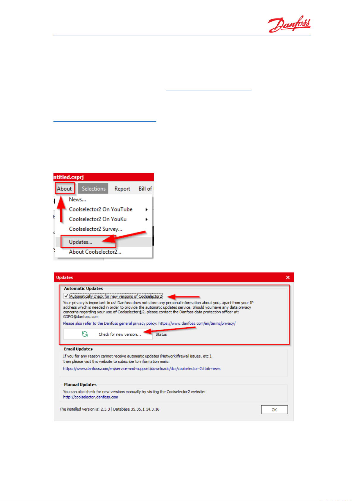
2 Check for latest version
Before you start using the standard PC version of Coolselector®2, please make sure you have the
latest version, by going to the “About | Updates” menu:
Once you see the Updates screen, click on the “Check for new version” button:
Note that, if you cannot update automatically (i.e. due to your company policies), it is possible to
subscribe to an email service which will notify you whenever a new version is released.
Coolselector®2 User Guide
4
Once you have clicked the button, Coolselector®2 will notify you if there is a newer version
available. If that is the case, you can install the new version directly from the prompt.
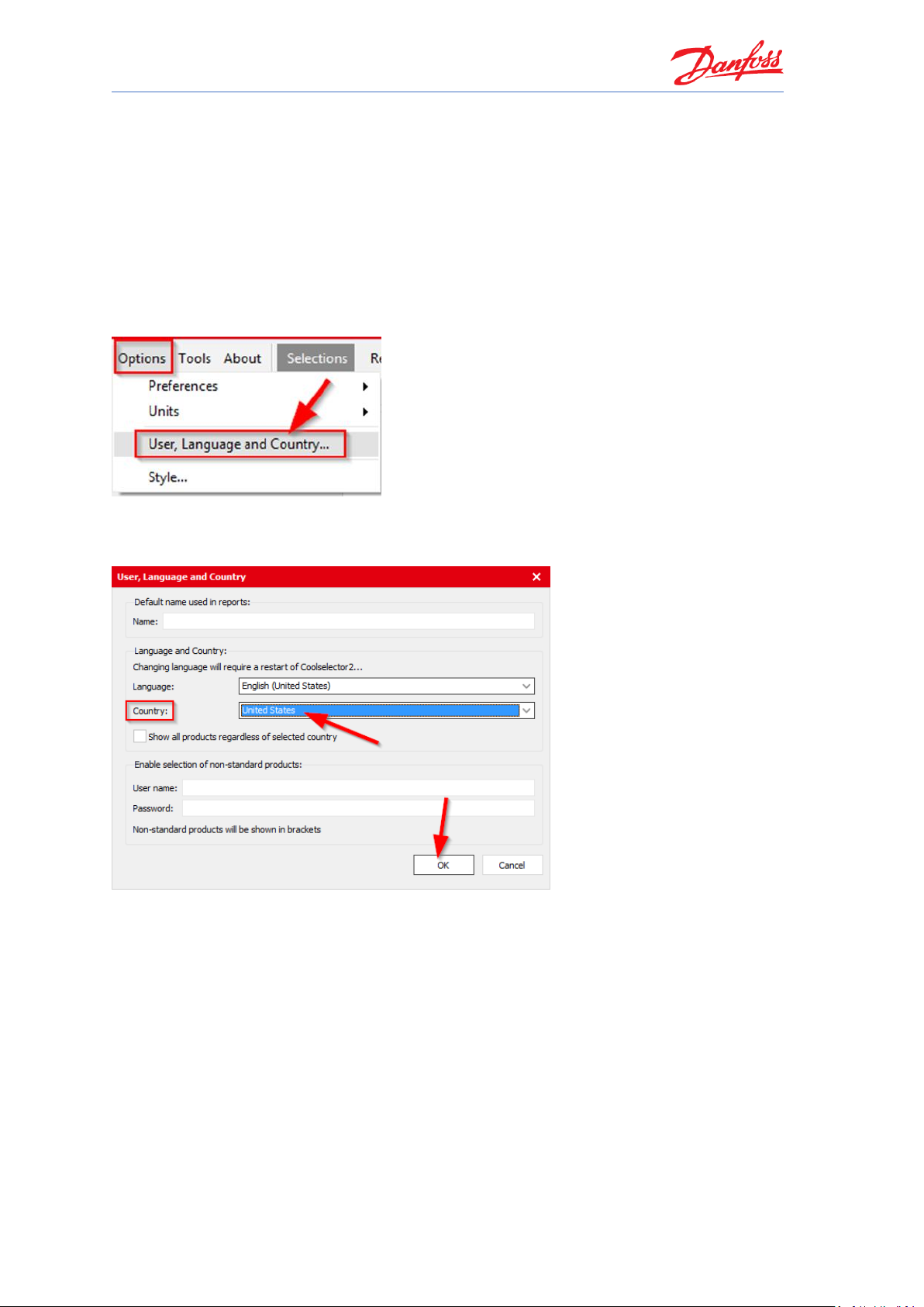
3 Country and language settings
Before first use, please also ensure you have set the country and language based on your
preferences.
You can set the preferences for country and language in “Options | User, Language, Country”
menu:
As an example, you can change your country to ‘USA’ as in the following example;
From the drop down, set your country to ‘United States’ and click OK:
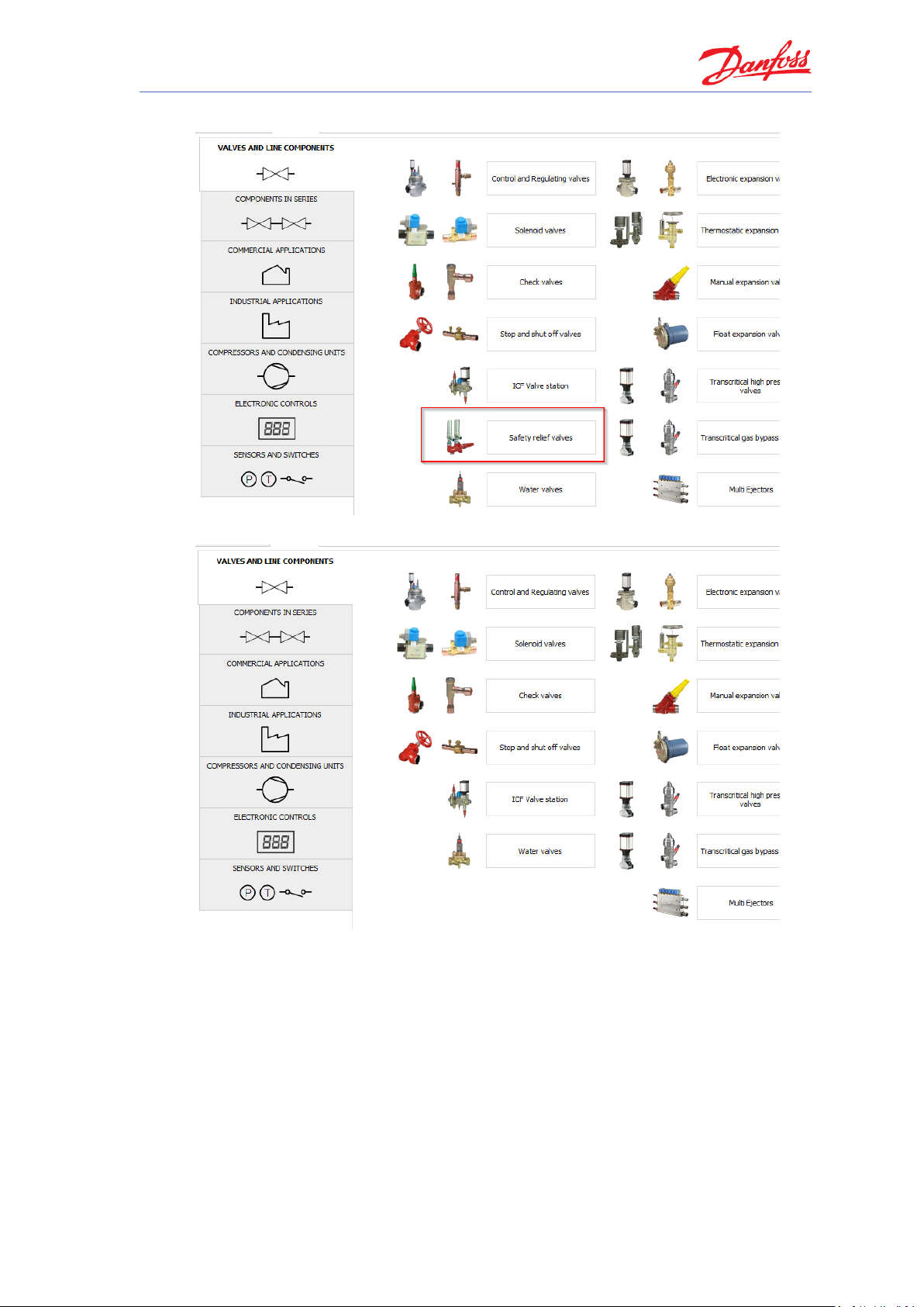
When you change your country to USA, you will see that the available components in “Valves
and Line Components” have changed. You will no longer be able to select “Safety relief valves” –
the reason being that Danfoss does not sell safety valves for the US market (this might change in
the future).
The important thing to note here is that Coolselector®2 will use your country setting to display
as relevant as possible information to you (this is even more pronounced for condensing units,
where each unit has a specific sales region).
On the next page, you will find some examples of this:
Coolselector®2 User Guide
1. Country = Denmark (or any other EU country as an example):
2. Country = United States:
Do not forget to change the settings back to your preferred ones (i.e. your own country).
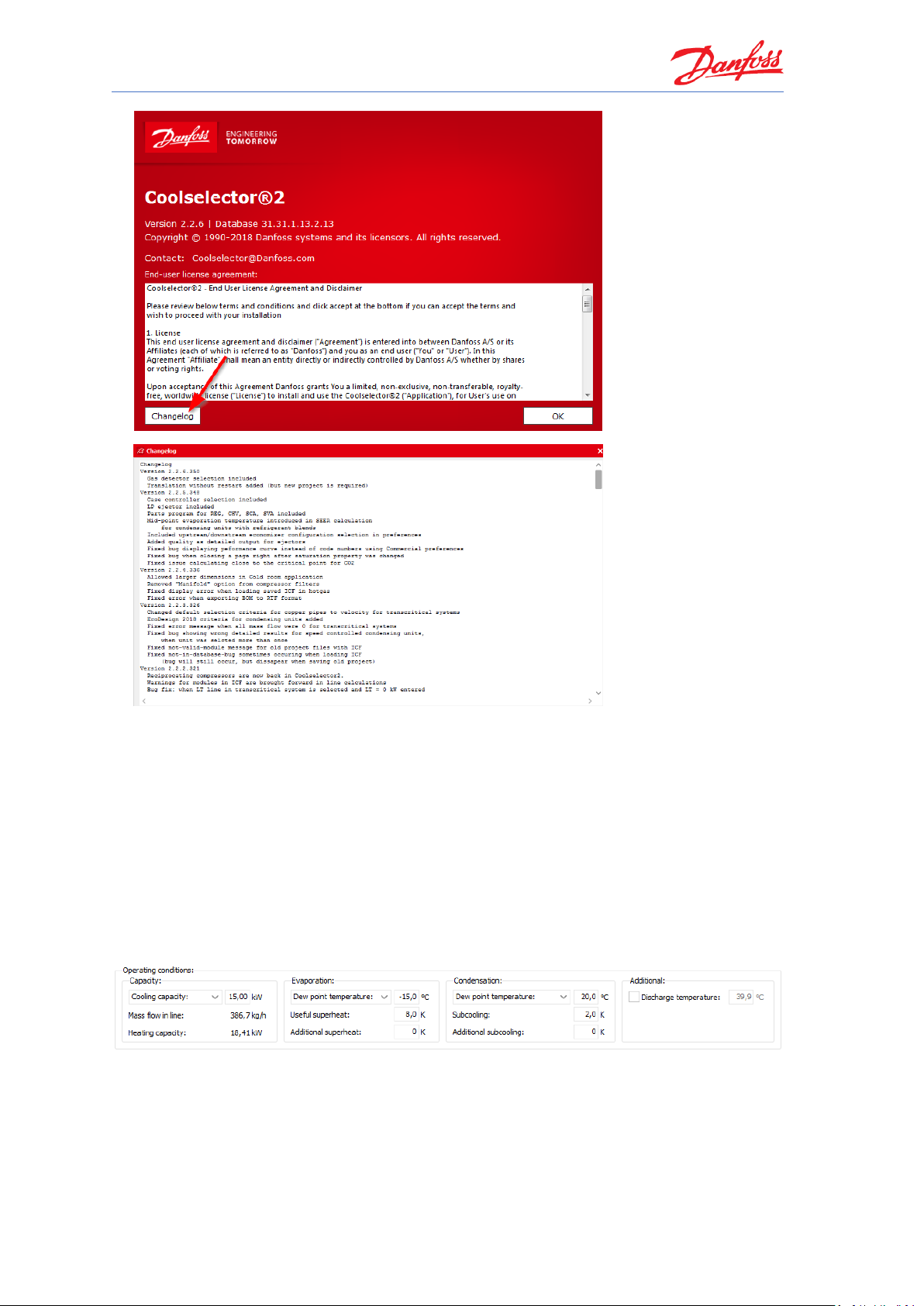
4 How to find out what is new in Coolselector®2
To see the latest changes in Coolselector®2, go to the “About | About Coolselector2” menu and
click the <Changelog> button:
Coolselector®2 User Guide
6
’
Also, check out the “About | News” menu item for new product releases.
5 Basic component selection
In the following part of this user guide, we will go through creating a project in which we try
selection and calculation for a few components in a very simplified refrigeration cycle as it can
be seen in the following graph and properties snippet. We will also discuss how to customize the
project with your own name, how to get bill of materials and how to generate a report for this
project. Make sure your preferences choice is set to “’all applications’ in “Options | Preferences
| All applications” (refer to chapter 21 if in doubt how you do this).
System Properties 1
Coolselector®2 User Guide
TC
DCR-DA
Speed 12±3 m/s
Refrigerant R404A
Copper DIN-EN 10 m
Speed 0,9±0,2 m/s
Copper DIN-EN 1 m
Speed 15±3 m/s
AKV
Load 80%
Condenser
Evaporator
Cycle Diagram 1
For the following explanations on basic component selection, we will use the information in
System Properties 1 and Cycle Diagram 1 above.
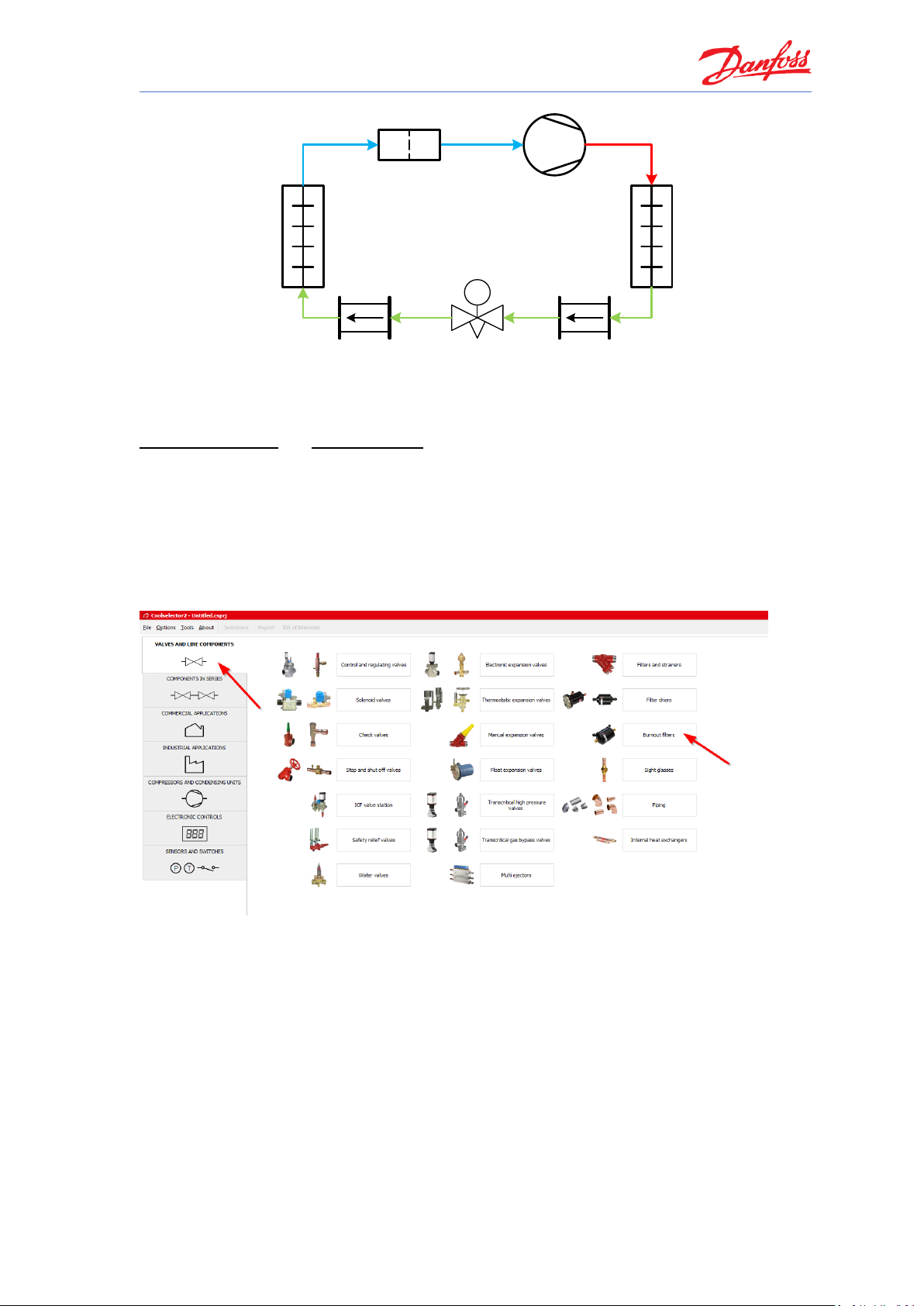
First, and to give you an overview of the “Valves and Line Components” part of Coolselector®2,
we will start by selecting a DCA-DA burnout filter for the suction line in a dry system with the
default operating conditions.
To do this, open Coolselector®2. Upon doing so, you will find that the program starts on the tab
for ‘Valves and Line Components’. From this screen, among the different component
functionalities, we will choose “Burnout filters”.
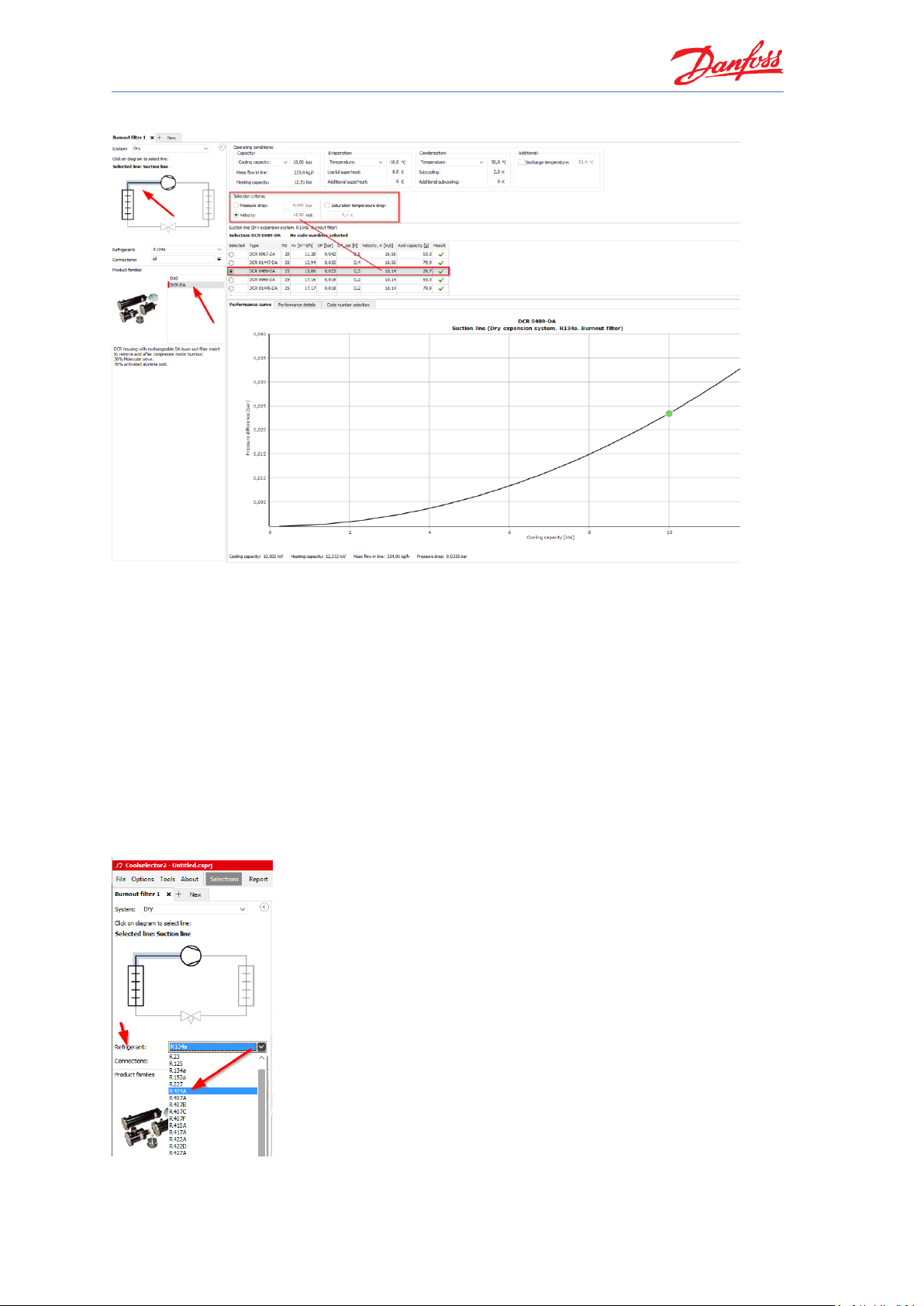
Coolselector®2 creates a dry system by default, and we then select the suction line and then
click on the DCR-DA in the product families. You will see the list of valid products and the best
Coolselector®2 User Guide
8
one matching the selection criteria as depicted in the snippet below:
Here you can also see the other parameters for the filter in the table, such as acid capacity, as
well as the pressure-drop as a function of changing the cooling capacity and keeping the other
parameters constant.
6 Changing the refrigerant
Coolselector®2 also allows you to change the refrigerant during product selection.
In our previous example we selected a DCR-DA using the standard settings (the default
refrigerant for DCR-DA is R134a). Now, let us try to change this to R404A.
Change the refrigerant by choosing R404A in the drop down ‘Refrigerant’ on the left-hand side:
Coolselector®2 User Guide
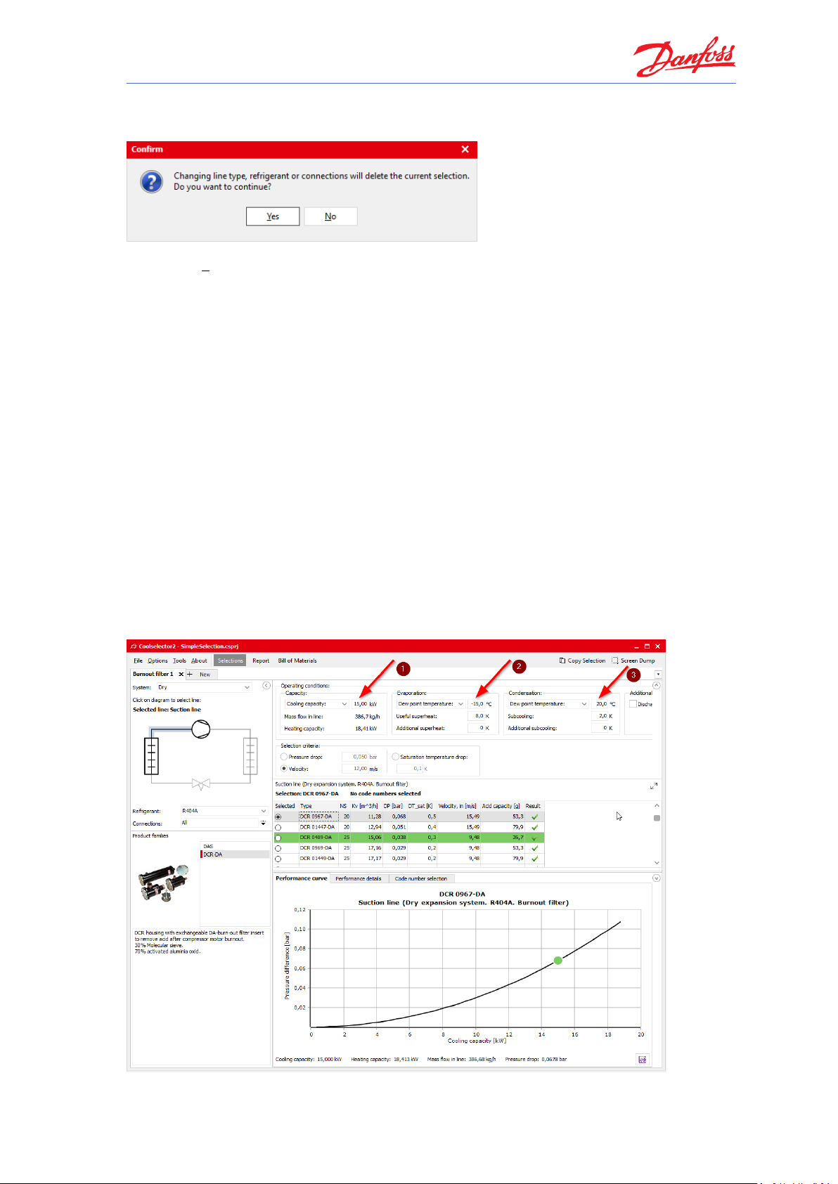
You may notice, that when you change the refrigerant, Coolselector®2 asks for a confirmation,
as this change means you are creating a new selection procedure.
By clicking “Yes”, a new selection will be made.
Please note that the ‘evaporation temperature’ and ‘condenser temperature’ are now changed
to ‘dew point temperature’. This is due to the fact that R404A is a glide-refrigerant and hence
there is reference required for the evaporator and condenser temperatures.
The current suggestion from Coolselector®2 for a best match to the operating conditions is “DCR
0967-DA”, which is different from the suggestion made by the exact same properties in the
system running with R134a; this is of course due to the different properties of the two
refrigerants.
7 Description of operating conditions
Using our examples with selection of a DCR-DA using the standard Coolselector®2 settings, but
with refrigerant R404A, we now try to adjust the cooling capacity, and dew point temperatures
for evaporation and condensation, respectively.
Increasing the capacity would increase the mass flow in line and hence the speed in the
component which results in a larger component. Decreasing the evaporation temperature
increases the mass flow-rate as the cycle COP would be lower. Decreasing the condensation
temperature has the opposite effect, which is the cause of the changes in the suggestion.
Coolselector®2 User Guide
10
Changing the system properties as shown in the snippet above, means that Coolselector®2 now
suggests the “DCR 0489-DA” as the best match instead of the previous “DCR 0967-DA”.
These are merely some examples to show you that the Coolselector®2 suggestion can change
and is easily affected by even small changes to the system properties.
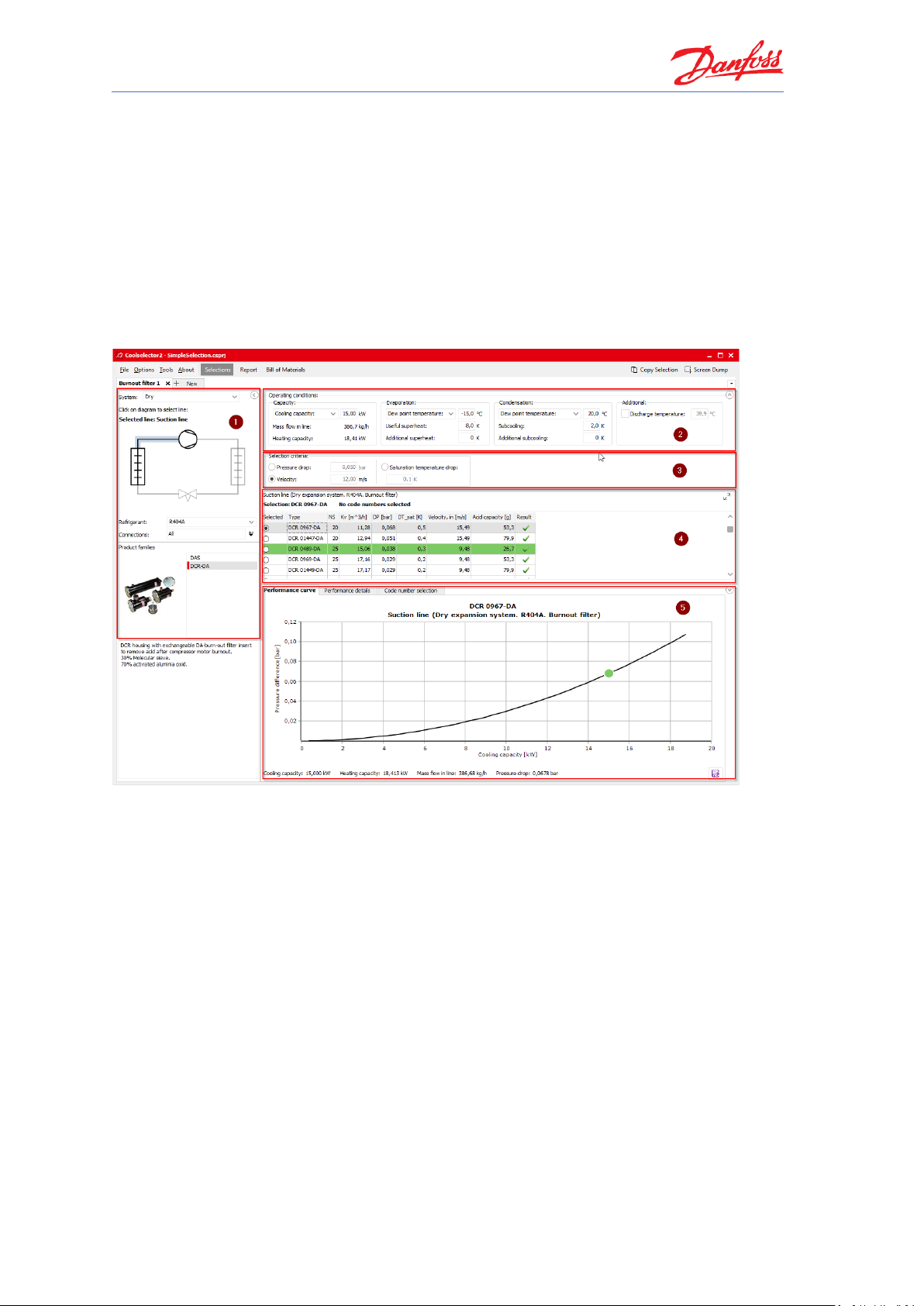
8 Different screen segments
In the calculation and selection interface of Coolselector®2, you will find that the screen is
separated in to five different segments:
1. Segment “1” is dedicated to the application criteria for your selection. These criteria
include, but are not exclusive to, system type, line, refrigerant, connection type, and
product family.
2. Segment “2” is where you insert your system operating conditions, such as cooling
capacity, evaporation and condensation temperature, and useful superheat. These
operating conditions have significant impact on the calculations and a lack of due care
when filling them in might lead to inapplicable results. Whereas great care has been
taken to set meaningful default conditions, there is no guarantee that these will mirror
the operating conditions for your system design.
3. Segment “3” is dedicated to the product selection criteria for the suggestion to be made
in the next segment based on your inputs in functionality criteria and operating
conditions segments.
4. In segment “4” you will find the selection table. In this area you will see the options
matching the functionality criteria and operating conditions that you specified in the
selected family. For each calculation, Coolselector®2 has a ‘suggestion’ which remains
highlighted in green based on your input in the product selection criteria input. The
selection table also includes some of the most relevant information for the product.
Coolselector®2 User Guide
5. In segment “5”, you will find the performance details and information about the chosen
product from the previous segment. This information updates as you choose other
products from the list.
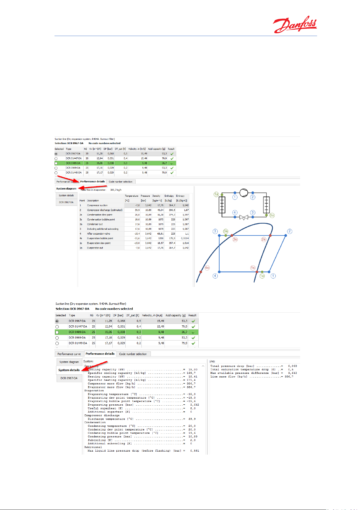
9 Check the calculations details
After making any calculation and/or selection within Coolselector®2, you can click on the
“performance details” tab, and check the system diagram calculations, system details and the
performance of the selected product from the list in the corresponding tabs.
System diagram and different points calculations:
System calculation details:
Coolselector®2 User Guide
12
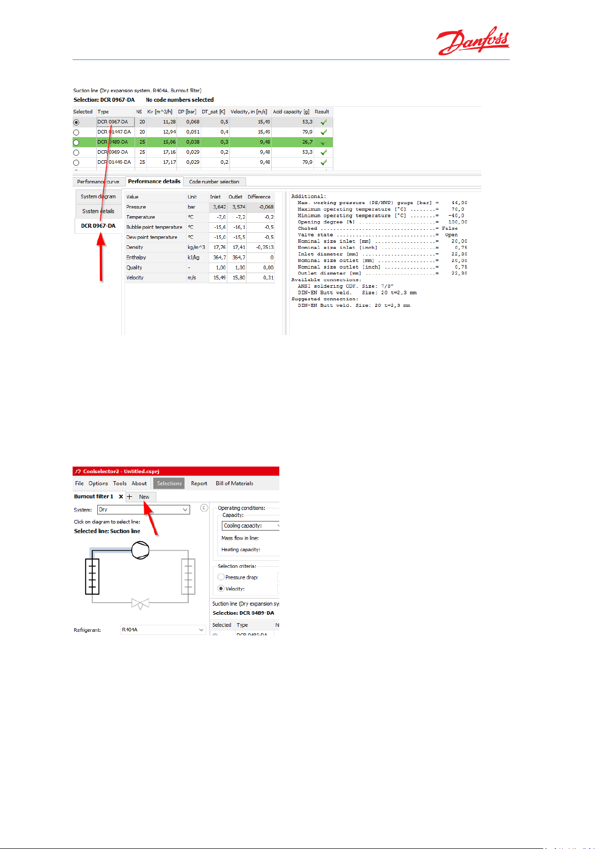
Product performance details:
Notice that the performance details are presented for the selected product only. You can click
on any of the products in the list and see the calculations for the selected product.
10 Adding a new tab
You can add a new tab for any new selection by clicking the “+ New” tab on the top next to your
existing tabs:
NB! Note that Coolselector®2 keeps your operating conditions for the system based on your
selection in the previous tab.

Coolselector®2 User Guide
11 Saving your project
To save the project, open File | Save Project… or click “Ctrl+S” on the keyboard. You will then be
asked for the name and the location of your project:
You can also use the “Save Project As…” option to save it with a different name or “Save and
Send…” option to save and send it to a customer or a colleague.
12 Loading a saved project
You can load the previously saved project from the menu “File | Open Project”… or by clicking
“Ctrl+O” on the keyboard.

Coolselector®2 User Guide
14
13 Selection of components in series
To calculate on components in series, first, create a new tab and select the option “Components
in Series” and then the liquid line in a dry system:
Now you need to add the components to the line. To do so, first you need to select the
functionality you would like to add to the line, and then double click on the family or drag the
family and drop it in the location that you need it.

Coolselector®2 User Guide
Add a Copper pipe with DIN-EN connection to the line and set its length to one meter:
Now you need the AKV electronic expansion valve:
Notice that Coolselector®2 automatically added a “Copper expander DIN-EN 15 × 18” between
the two components. The software recognizes the material of the piping as well as the
connection sizes and standard between two components. When two connections do not match,
it adds the required expander/reducer between the two componets for common cases, or
informs you in the row shown by the blue triangle and you can fix the connection problem
manually by adding an expander/reducer from the proper family in the piping function.

Coolselector®2 User Guide
16
Now the pipe after the expansion valve:
As can be seen, there are no warnings in the selected pipe, since the expansion is happening
entirely in the expansion valve.
It is also interesting to notice that the load for the AKV valve has increased. This is due to the fact
that the added pipes after the valve increase the pressure drop and hence the opening load of
the valve increases. Additionally, as can be seen, the target criteria for the pipe suggestion after
the expansion valve are clearly different to the one before the expansion valve.
Correct selection of an AKV valve or any other pulse modulated valve requires extra care, so
please be sure to pay close attention to your selection criteria, before making your selection.
The benefit of using components in series, is that in this case, Coolselector®2 calculates
components one after another. Furthermore, you can see the collective effect on the
performance curve for the components in the liquid line and the need for an expander/reducer
if you want to select the suggested components. The detailed calculation of each component
with the right inlet condition as shown by numbers 1-5 on the snippet can also be extracted.

Coolselector®2 User Guide
Note that if you need to replace components in the line, you can do so by simply dragging the
component to the preferred position and dropping it there.
The suggestions for components in series calculation use the default selection targets and values
in Coolselector®2. However, if you want to select another component from the same family, you
can do so by clicking on the icon of the component in the line and choosing the preferred one in
the pop-up menu. In this case, as a good design practice, it is better to avoid having a reducer
after the expansion valve. To do so, you can simply remove the reducer using the close sign on
the top right-hand side of the reducer and select the size of the pipe which fits the expansion
valve outlet:
You can see the share of each component on the pressure drop on top of the calculation details.
As you can see, the connections fit and, furthermore, the pressure drop after the expansion
valve is reduced significantly and is happening correctly in the AKV valve. You can also see the
relevant calculation details such as min and max capacity in the details.

Coolselector®2 User Guide
18
14 Compressor selection
To select a compressor for a system, we will use the following requirements:
1. Application: Refrigeration
2. Power supply: 50 Hz
3. Refrigerant: R404A
4. All compressor types.
5. Fixed speed
To begin selection, create a new tab and choose the option “Compressors and condensing
units”. Then select “Compressors”.
Check the operating conditions are set to:
Set the application criteria as they were specified in the beginning of this section:
1. Application: Refrigeration
2. Power supply: 50 Hz
3. Refrigerant: R404A
4. All compressor types.
5. Fixed speed

Coolselector®2 User Guide
Coolselector®2 now suggests MLZ058T4 as the best possible match:
The suggested compressor can achieve the requirement for this cycle and match the demand.
You can check that in the last column which indicates the match of the compressor to the given
operating conditions.
You can check the details about the compressors in the list on the performance tab in the
product performance and information segment. To check the COP at the working conditions,
choose the performance tab, then select the COP. Now you can check the COP for the

Coolselector®2 User Guide
20
compressor on working conditions:
You can also check the COP at this exact working condition in the selection segment:
15 Understanding superheat
Some superheat is required for the refrigerant at the compressor inlet to ensure avoidance of
liquid droplets in the compressor.
The useful superheat is the superheat inside the evaporator which contributes to the cooling
capacity. However, a very high useful superheat decreases the evaporator efficiency as well as
the density at the evaporator outlet which results in higher compressor consumption. This value
is set to 8 K by default in Coolselector®2.
Additional superheat happens after the evaporator in the suction line. A longer length of the
suction line would result in a higher additional superheat. This is set to zero by default as it is
highly affected by the length and size of the suction line which is not provided to Coolselector®2.
However, you should try to provide an accurate value or estimation for a good selection.
If you change the additional superheat to 5 K, the suggested compressor in Coolselector®2 will
change to MLZ058T2, which allows a slightly higher volumetric flow rate to support the given
cooling capacity.
The reason is that increasing the useful superheat would result in decrease of density after the
suction line at the compressor inlet. The mass flow rate required for the cooling capacity would
be the same (you can check that in the performance details tab), but a lower density means a
higher volumetric flow rate which results in demand for a slightly larger compressor. Another
important aspect regarding additional superheat is the discharge temperature which can be
affected significantly and would affect selection of components in the discharge line, as well as
compressors or condensing units.
Hence providing additional superheat correctly is important for proper selection and suggestion.

Coolselector®2 User Guide
16 Electronic controller selection
To select a controller for our system, we will use the following requirements:
1. Expansion Valve Type: EEV AKV
2. Number of Compressors: Single compressor
3. Communication: MOD bus
To begin selection, create a new tab and choose the option “electronic controls”. Then select
“case controllers”:
If you apply the requirements in the selection criteria segment, Coolselector®2 will suggest the
controllers that can satisfy the requirements:

Coolselector®2 User Guide
22
You can add additional criteria such as the “Dual case sections” requirement in the
“Refrigeration System” section:
As is evident from above, Coolselector®2 suggests the AK-CC 550B as the best matched
alternative for the given selection criteria.
17 Creating a report
Now, after going through the selections and calculation phase, we will create a report.
View the report by clicking on “Report” in the menu bar of Coolselector®2. This opens the report
section:

Coolselector®2 User Guide
The segment for the project information will be blank if you did not enter this information
before (in the settings). You can fill this in and modify the report to suit your requirements, the
following steps will show you how.
To add your name to Coolselector®2, open “Options | User, Language and Country
…” and then add your name and click “OK”
Now your name should be on the report preview section. You can also add a project
name. After that, click “Update” to update the report preview:
You can add/remove included information in the report. To do so, click on the “+”
sign beside each list to see the available options, or click on the “Collapse all”

Coolselector®2 User Guide
24
button. Add the required fields and click update and check the result. Note that
each list belongs to one tab on your “Selections” section:

Coolselector®2 User Guide
Click the “PDF” button at the top of the report preview to export your report as a
PDF. You have multiple options for your exported PDF, such as printing specific
pages in the report, adding extra information, or securing your pdf file with a
password. Investigate those options for further details.
You will then be asked for the name and the location of the document and you can
click “save”. If you selected the option “Open after export”, the report will then
automatically open.
18 Selecting a code number
Coolselector®2 will enable you to select the relevant code numbers for the selected products.
Depending on the product type, this code number can be accessed/modified differently.
If you are currently in the ‘report’ (following section 17), first, go to the “Selections” section by
clicking on the “Selections” button in the menu bar (see “1” in the snippet below).
Next, go to any open tab (in this case “Burnout filter 1” – see “2” in the snippet below) and
select the tab for code number selection (“3” in the snippet below). Then select the proper
casing and filters. E.g. in an example with a burnout filter, we would like to have the DIN
connection casing with copper connection to match our installation and a pack of 8 filter cores:

Coolselector®2 User Guide
26
Then go to the tab for liquid-line calculation and select the code number for the AKV valve. E.g.
we select the one with DIN-EN connection again to match our selection:
Now, for the compressor code number you need to go the “Information” tab, where you can
select the code number and also see other information about the compressor, including the

Coolselector®2 User Guide
spare parts available for the compressor:
And for the case controller the code number is just visible after you click on your selected
controller:
19 Bill of materials
After you have selected the relevant code numbers for the products in your Coolselector®2
project, you can check out the bill of materials. You just need to click on the “Bill of Materials”
button in the menu bar:

Coolselector®2 User Guide
28
To include the piping, you just need to click on the option “include piping”:
To export the bill of materials as an Excel file, click on the “Excel” button at the top of the bill of
materials preview. Then specify the destination and the name for the exported file:

Coolselector®2 User Guide
20 Customization – units and conversions
To convert all units in Coolselector®2 from the default international units to e.g. American or SI
units is very simple. To change the unit system to e.g. American units, you simply need to select
it in “Options | Units | American”:

Coolselector®2 User Guide
30
You can also select the “Tools | Show operating conditions” menu and see the equivalent of
operating conditions in different unit systems:
21 Customization – change application
Coolselector®2 allows you to customize your product view to either ‘all applications’,
‘commercial applications’ or ‘industrial applications’ respectively.
You can set the preferred application to e.g. commercial applications in “Options | Preferences |
Commercial applications”:
You will notice that following this change, the “new” tab interface has changed in the order as
well as the available options. This is to provide a better overview for you.
You can see that, following the change to ‘commercial applications’, some of the options which
are more specific to industrial applications such as “ICF valve station” are now no longer part of

Coolselector®2 User Guide
the “new” tab interface:
22 Customization – columns in selection table
You can modify which columns you see in your selection table and change the order for the
calculations and selections made in the “Valve and Line Components” option as well as
“Compressors”. To do so, right click on the table header and select “Manage Columns…”. This is
step 1 and 2 in the following snippet:
To remove the columns e.g. after the “Mass flow”, you can simply uncheck them in
the list as shown by step 3.

Coolselector®2 User Guide
32
To replace “Heating” with “COP cooling”, you should click on Heating and then click
on the top arrow as shown by steps 4 and 5.
Then you can click OK to update the table. Coolselector®2 will remember your
modifications next time you run it and you can always go back to the default table by
clicking on default in “Manage Columns…”:
23 Customization – user interface
Coolselector®2 allows you to resize different segments or minimize the segments to see the
information more clearly. Coolselector®2 will remember previous modifications, but sizes will
reset to default when you start Coolselector®2 again.
You can minimize the “Operating conditions” segment by clicking on the button at
the top right-hand side of the segment:

Coolselector®2 User Guide
To resize any of the segments, you can click and drag on the border in order to see
information more easily:

Coolselector®2 User Guide
34
After setting the general criteria and operating conditions and the product
suggestion criteria, sometimes it is handy to expand the segments for the selection
table and product performance and information to fullscreen. You can do that by
clicking on the expand button in the top right-hand corner of the selection table:

Coolselector®2 User Guide
24 Customization - preferences
The settings we discuss in this part of the user guide do not need to be modified in most cases,
as we, in the Coolselector®2 team, constantly try to optimize the default preferences based on
our customer requirements.
To create custom preferences, use “Options | Preferences | Edit preferences…”:
You will see the “Preferences” window. On top you have the different preferences which are
customizable.
You can select “Dry expansion systems” among the options for the “Default system” and
add/remove options for your selection and calculations among the product pages as well as
control their sorting order within the interface:

Coolselector®2 User Guide
36
Next, you can go to the “Operating conditions” tab by clicking on the top bar and changing the
default operating conditions:
You can also go to the “Valves and Line Components” tab and select the type of components you
would like to see for your selections/calculations and the families in each functionality, as well as
connection sizes and some more options:
In the tab for compressors and condensing units, you will find the relevant settings for those
products. You can choose which products to see and even see the rating conditions and create

Coolselector®2 User Guide
custom ones. You can also set the limits to those you prefer:
If you click the “OK” button to apply your settings, Coolselector®2 will ask you to name your
preferences and save them. Coolselector®2 will keep the default settings intact so you can
always go back to the predefined preferences easily:

Coolselector®2 User Guide
38
Next time you open Coolselector®2, it will keep your preferences and you can see that in
the list of the preferences. You can come back to this menu and edit, rename or delete
your preferences at any time.
You can also see that the new tab menu has changed based on your new preferences.
On the top right-hand side of the window you will be able to see the recent projects and
load them easily.
25 Advanced settings – calculation and selection criteria
Please note that changing the following settings can affect the results of the selection or
calculation process and lack of due care can have a negative effect on the suggestions and
default calculations. However, the advanced settings enable you to customize and improve your
experience and even modify the calculations if you find it necessary.

Coolselector®2 User Guide
The default values for the calculations can be changed in “Valves and Line Components |
Advanced | Default values” in the preferences window:
The selection criteria for all the components supported by Coolselector®2 can be found in
“Valves and Line Components | Advanced | Selection critera”:

Coolselector®2 User Guide
40
26 Advanced settings – custom unit system
To create a custom unit system, you need to go to “Options | Units | Custom…”. Then you will
find the unit used for each of the default unit systems and you can create your own:
By clicking OK, you will be asked to save your custom unit system and give it a name. It will then
appear on the list of unit systems similar to your custom preferences.

Coolselector®2 User Guide
│ │2019.06
 Loading...