

Page 1

Exercises for Coolselector®2. Training material for use in courses and self-studies for both internal and external use.
Not for use as a design guide. Always remember that selection software is only as good as the person using it.
2018-06-04 | Version 3.0.0
Page 2

Page 3

Coolselector®2 Exercises
i
Contents
1 Introduction .............................................................................................................................. 1
2 Coolselector®2 - end user license agreement and disclaimer ................................................. 2
1. License .................................................................................................................................. 2
2. Proprietary rights .................................................................................................................. 2
3. Third party components ....................................................................................................... 2
4. Disclaimer of warranty ......................................................................................................... 2
5. Limitation of liability ............................................................................................................. 3
6. Miscellaneous ....................................................................................................................... 3
3 General information and basic selection ................................................................................. 5
Exercise 3.1 Installing and setting up Coolselector®2 .................................................................. 5
Solution 3.1 Installing and setting up Coolselector®2 .................................................................. 6
Exercise 3.2 Starting a new project and basic component selection ......................................... 11
Solution 3.2 Starting a new project and basic component selection ......................................... 12
Exercise 3.3 Selecting components in series .............................................................................. 21
Solution 3.3 Selecting components in series .............................................................................. 22
Exercise 3.4 Understanding superheat and selecting a compressors ........................................ 27
Solution 3.4 Understanding superheat and selecting a compressor ......................................... 28
Exercise 3.5 Selecting electronic controllers .............................................................................. 31
Solution 3.5 Selecting electronic controllers .............................................................................. 32
Exercise 3.6 Creating a report, bill of materials and code numbers .......................................... 33
Solution 3.6 Creating a report, bill of materials and code numbers .......................................... 34
Exercise 3.7 Changing predefined preferences and customizing the interface ......................... 41
Solution 3.7 Changing predefined preferences and customizing the interface ......................... 42
Exercise 3.8 Changing the advanced settings ............................................................................. 47
Solution 3.8 Changing the advanced settings ............................................................................ 48
4 Commercial applications ........................................................................................................ 53
Exercise 4.1 Selecting a thermostatic expansion valve .............................................................. 53
Solution 4.1 Selecting a thermostatic expansion valve .............................................................. 54
Exercise 4.2 Selecting an electronic expansion valve ................................................................. 57
Solution 4.2 Selecting an electronic expansion valve ................................................................ 58
Exercise 4.3 Selecting a solenoid valve ...................................................................................... 63
Solution 4.3 Selecting a solenoid valve ...................................................................................... 64
Page 4

Coolselector®2 Exercises
ii
Exercise 4.4 Selecting a check valve with reciprocating compressors ....................................... 69
Solution 4.4 Selecting a check valve with reciprocating compressors ...................................... 70
Exercise 4.5 Selecting a check valve with scroll compressors ................................................... 73
Solution 4.5 Selecting a check valve with scroll compressors ................................................... 74
Exercise 4.6 Selecting a check valve for the condenser line ...................................................... 77
Solution 4.6 Selecting a check valve for the condenser line ...................................................... 78
Exercise 4.7 Selecting an evaporation pressure control valve for a one-to-one system ........... 81
Solution 4.7 Selecting an evaporation pressure control valve for a one-to-one system .......... 82
Exercise 4.8 Selecting an evaporation pressure control valve for a power-pack system .......... 85
Solution 4.8 Selecting an evaporation pressure control valve for a power-pack system .......... 86
Exercise 4.9 Calculating heat load and selecting components for a cold room ........................ 89
Solution 4.9 Calculating heat load and selecting components for a cold room ........................ 90
5 Industrial applications .......................................................................................................... 103
Exercise 5.1 Selecting a valve in liquid feed line ...................................................................... 103
Solution 5.1 Selecting a valve in liquid feed line ...................................................................... 104
Exercise 5.2 Selecting an expansion valve ............................................................................... 107
Solution 5.2 Selecting an expansion valve ............................................................................... 108
Exercise 5.3 Selecting an ICF .................................................................................................... 111
Solution 5.3 Selecting an ICF .................................................................................................... 112
Exercise 5.4 Selecting components in series ........................................................................... 113
Solution 5.4 Selecting components in series ........................................................................... 114
Exercise 5.5 Selecting a safety valve ........................................................................................ 117
Solution 5.5 Selecting a safety valve ........................................................................................ 118
Exercise 5.6 Selecting components in hot gas defrost ............................................................ 121
Solution 5.6 Selecting components in hot gas defrost ............................................................ 122
Exercise 5.7 Selecting components for an industrial evaporator valve station ....................... 123
Solution 5.7 Selecting components for an industrial evaporator valve station ...................... 124
6 CO₂ system calculations ....................................................................................................... 125
Exercise 6.1 Selecting a high-pressure valve ........................................................................... 125
Solution 6.1 Selecting a high-pressure valve ........................................................................... 126
Exercise 6.2 Selecting a gas bypass valve................................................................................. 131
Solution 6.2 Selecting a gas bypass valve ................................................................................ 132
Exercise 6.3 Selecting an expansion valve ............................................................................... 137
Solution 6.3 Selecting an expansion valve ............................................................................... 138
Page 5

Coolselector®2 Exercises
iii
Exercise 6.4 Selecting a high-pressure ejector ......................................................................... 141
Solution 6.4 Selecting a high-pressure ejector ......................................................................... 142
Exercise 6.5 Selecting a low-pressure ejector .......................................................................... 149
Solution 6.5 Selecting a low-pressure ejector .......................................................................... 150
7 Compressors ......................................................................................................................... 153
Exercise 7.1 Selecting a compressor and finding related technical information ..................... 153
Solution 7.1 Selecting a compressor and find related technical information .......................... 154
Exercise 7.2 Understanding the challenges for compressor selection ..................................... 165
Solution 7.2 Understanding the challenges for compressor selection .................................... 166
Exercise 7.3 Selecting spare parts for compressors and creating a report .............................. 171
Solution 7.3 Selecting spare parts for compressors and creating a report .............................. 172
8 Condensing units .................................................................................................................. 179
Exercise 8.1 Selecting a condensing unit .................................................................................. 179
Solution 8.1 Selecting a condensing unit.................................................................................. 182
Exercise 8.2 Selecting spare parts for a condensing unit ......................................................... 189
Solution 8.2 Selecting spare parts for a condensing unit ......................................................... 190
Exercise 8.3 Selecting a condensing unit in systems with long suction lines ........................... 193
Solution 8.3 Selecting a condensing unit in systems with long suction lines ........................... 194
Exercise 8.4 Selecting an Optyma Plus™ inverter .................................................................... 195
Solution 8.4 Selecting an Optyma™ Plus inverter .................................................................... 196
Exercise 8.5 Finding AWEF values for condensing units in North America .............................. 201
Solution 8.5 Finding AWEF values for condensing units in North America .............................. 202
Exercise 8.6 Evaluating a condensing unit based on the Ecodesign Directive ......................... 207
Solution 8.6 Evaluating a condensing unit based on the Ecodesign Directive ......................... 208
Page 6

Page 7

Coolselector®2 Exercises
1
Introduction
This document contains a number of exercises designed to introduce you to Coolselector®2 and
take you through the capabilities of the software. In these exercises, we will try to cover both
the general aspects of Coolselector®2 and also some of the more challenging procedures where
you should take extra care when designing your system.
The exercises in this document are not meant as a design guide. The exercises are designed for
the sole purpose of taking you through the features of Coolselector®2. Please also read and
accept the End-user license agreement in the next chapter before continuing with the exercises.
The document is structured so that each exercise is followed by a possible solution.
Coolselector®2 is designed so that it provides an optimized interface based on the application,
user preferences and the type of components you want to calculate/select. Hence, we have tried
to split the exercises into these main Coolselector®2 functionalities and cover the general
aspects in the first chapter.
The exercises are divided into: general information and basic selection, commercial applications,
industrial applications, CO₂ Systems, compressors and, finally, condensing-units; where each
section is designed by an experienced Danfoss expert in the specific functionality. Users coming
from the various application areas would benefit from the exercises in other functionality areas,
despite the differences in the system setups, refrigerants, or other parameters. This is since the
selection methods are similar, and the notes from different experts provide a more
comprehensive understanding and cover more fine tips, all of which can help you to reach the
best results.
All units used in this document are international units. Coolselector®2 supports many different
units and supports switching back and forth between the units in an easy way, so you should be
able to go through the exercises using your preferred units.
Page 8

Coolselector®2 Exercises
2
Coolselector®2 - end user license agreement and disclaimer
Please review below terms and conditions and accept them before proceeding with the
exercises.
1. License
This end user license agreement and disclaimer ("Agreement") is entered into between Danfoss
A/S or its Affiliates (each of which is referred to as "Danfoss") and you as an end user ("You" or
"User"). In this Agreement "Affiliate" shall mean an entity directly or indirectly controlled by
Danfoss A/S whether by shares or voting rights.
Upon acceptance of this Agreement Danfoss grants You a limited, non-exclusive, nontransferable, royalty-free, worldwide license ("License") to install and use the Coolselector®2
("Application"), for User's use on any device that User owns or controls. The License is granted
subject to User's compliance with the following:
a) The terms of this Agreement
b) Danfoss Terms of Use (available at www.Danfoss.com)
c) Danfoss Privacy Policy (available at www.Danfoss.com)
2. Proprietary rights
This License and the Application contains proprietary information which is owned by Danfoss
and protected by applicable intellectual property rights. Except as expressly permitted herein,
such Danfoss information herein may not
i. be used for any purpose except in compliance with this Agreement,
ii. be copied or reproduced in any form, or
iii. be modified, rented, leased, sold, distributed or exploited commercially.
Danfoss reserves the right to change, suspend, remove or disable User's access at any time
without notice. The Danfoss name, Danfoss logo and other Danfoss trademarks, graphics and
logos are trademarks or registered trademarks of Danfoss or its affiliated companies. User is
granted no right or license with respect to such trademarks.
3. Third party components
The Application may include certain third party software components ("Third Party
Components") including open source and free software components, each of which has its own
copyright and its own license conditions ("Third Party License"). A list of included Software
Components and their respective licenses can be found in the third_party_licenses.txt file.
To the extent any Third Party License grants the User rights to use, copy or modify the Open
Source Component that are broader or narrower than the rights granted in this Agreement, then
such rights shall take precedence over the rights and restrictions granted in this Agreement
solely for such Third Party Components.
4. Disclaimer of warranty
This License is provided on an "as is" and "as available" basis for the intended purposes as
determined by Danfoss only and any use hereof is at User's sole risk. The Application and results
and information generated thereby cannot substitute technical advice but must be verified by
the User, they are not promises and should not be relied on as accurate data or analyses.
Page 9

Coolselector®2 Exercises
3
Danfoss disclaims all warranties and conditions regarding the Application, whether express,
implied, or statutory, including, but not limited to, conditions of merchantability, satisfactory
quality, fitness for a particular purpose, accuracy and non-infringement of third parties' rights.
Danfoss does not warrant that the Application will meet your requirements or that the
operation hereof will be uninterrupted or error-free.
5. Limitation of liability
To the extent not prohibited by law, in no event shall Danfoss be liable for any direct, special,
indirect or consequential damages, whatsoever, including, without limitation, damage to
property, damages for loss of savings or profits, or loss of data arising out of any use of the
Application.
6. Miscellaneous
The License shall automatically terminate upon User's breach of any of the terms of this
Agreement. Danfoss may terminate the License at its sole discretion without prior notice.
This Agreement and the License is subject to the substantive law of Denmark. Any dispute
arising out of or in connection with this Agreement shall be submitted to the exclusive
jurisdiction of the courts in Denmark.
App License Terms, 2014-08
Page 10

Page 11

Coolselector®2 Exercises
5
General information and basic selection
Installing and setting up Coolselector®2
We need to get Coolselector®2 up and running if you have not done so already. You can
download and install Coolselector®2 from http://coolselector.danfoss.com.
Check if there are any updates available for Coolselector®2?
Change the country and language based on your preferences:
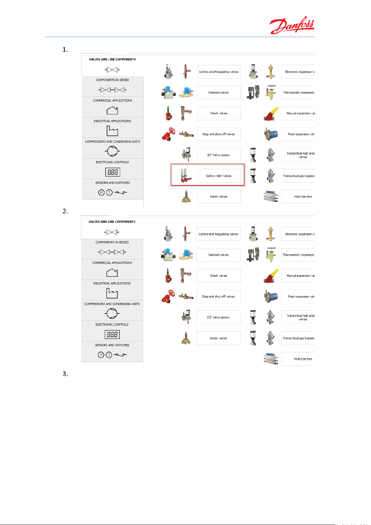
1. Note, the type of components you can select on the “Valves and Line Components”
page. Then, change the Country to USA (if your country is USA, change it to, for
example, Denmark)
2. Have the available components in “Valves and Line Components” changed?
3. Change your Country back (or select to show all products)
What was the last change in this release of Coolselector®2?
Page 12
Coolselector®2 Exercises
6
Installing and setting up Coolselector®2
You can download and install Coolselector®2 from http://coolselector.danfoss.com.
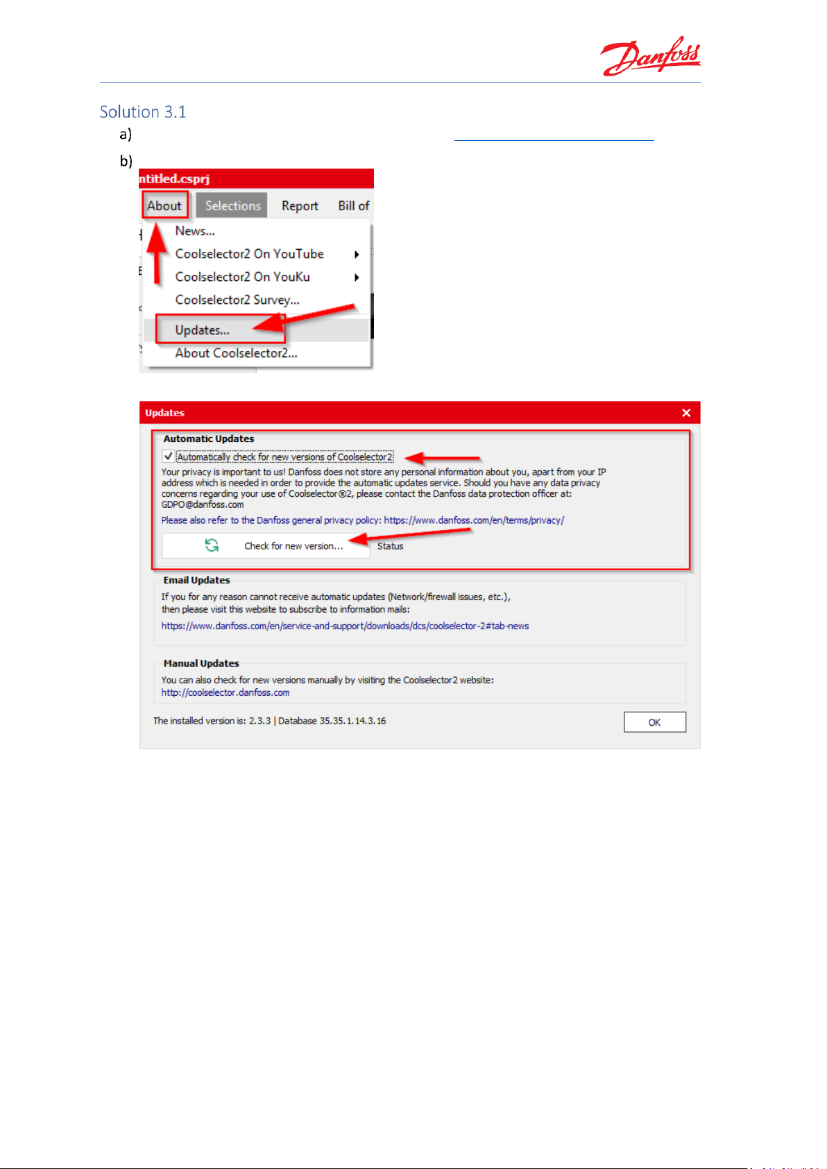
Go to the “About | Updates” menu:
Once you see the ‘Updates screen’, click on the “Check for new version” button:
Note that, if you cannot update automatically (i.e. due to your company policies), it is
possible to subscribe to an email service, which will notify you whenever a new version is
released.
Once you have clicked the button, Coolselector®2 will notify you if there is a newer
version available. If that is the case, you can install the new version directly from the
prompt.
Page 13
Coolselector®2 Exercises
7
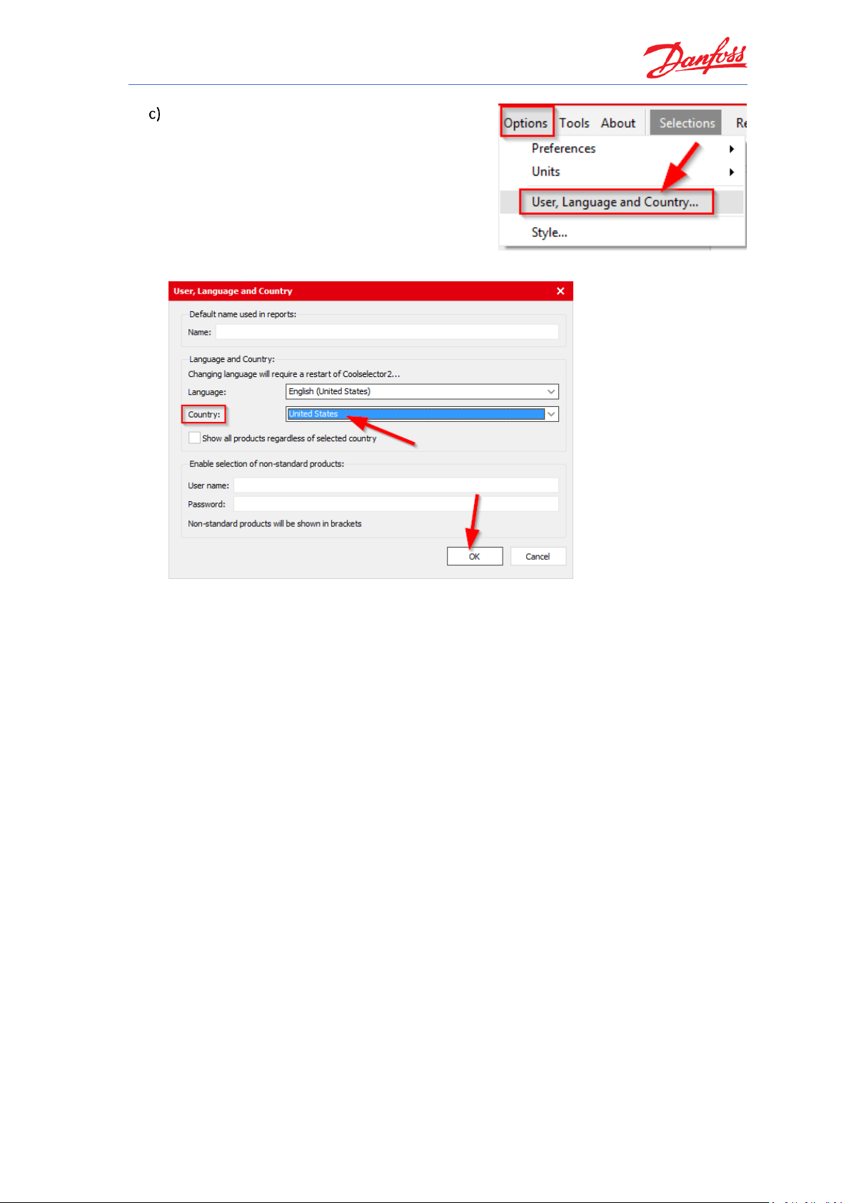
You can set the preferences for the country and
language in “Options | User, Language, Country”
menu. As an example, for this exercise, you can
change your country to ‘USA’:
From the drop down, set your country to ‘United States’ and click OK:
When you change your country to USA, you will see that the available components in
“Valves and Line Components” have changed. You will no longer be able to select “Safety
relief valves” – the reason being that Danfoss does not sell safety valves for the US market
(this might change in the future).
The important thing to note here is that Coolselector®2 will use your country to display as
relevant as possible information to you (this is even more pronounced for condensing
units, where each unit has a specific sales region).
Page 14
Coolselector®2 Exercises
8
Country = Denmark (or any other EU country as an example):
Country = United States:
Do not forget to revert back to your preferred settings.
Page 15
Coolselector®2 Exercises
9
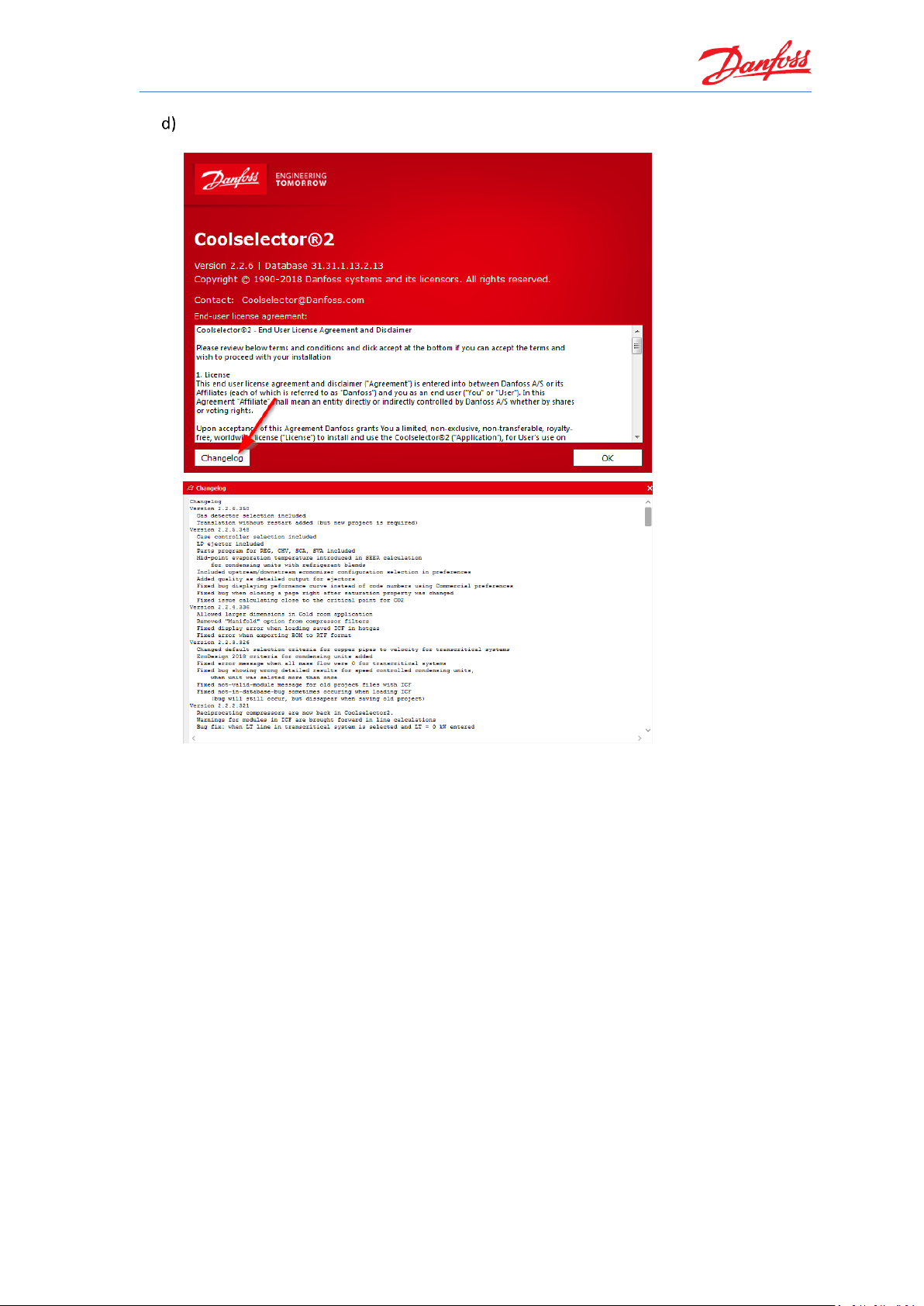
To see the latest changes in Coolselector®2, go to the “About | About Coolselector2”
menu and click on the <Changelog> button:
Also, check out the “About | News” menu item for new product releases.
Page 16

Page 17
Coolselector®2 Exercises
11
In the following part of this section, we will go through creating a project in which we try
selection and calculation for a few components in a very simplified refrigeration cycle as it can
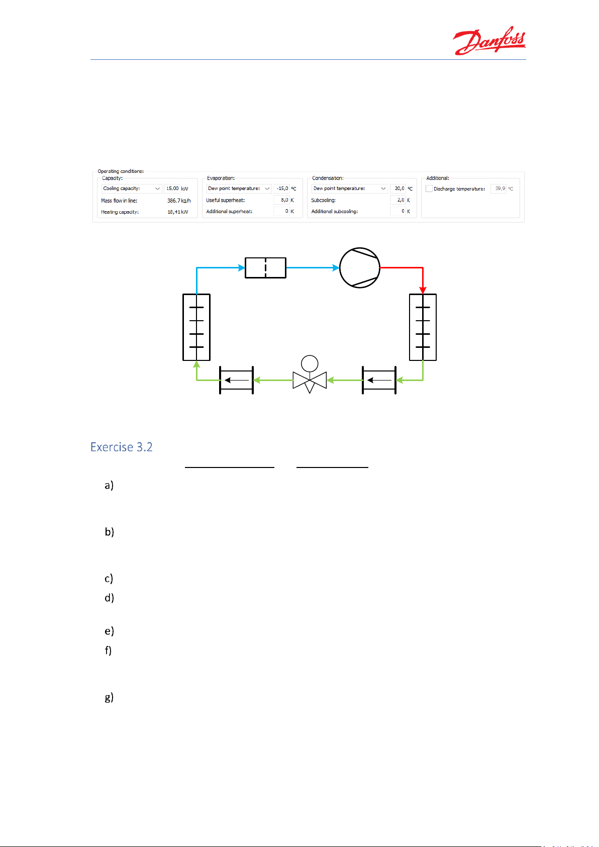
be seen in the following graph and properties snippet. Following this, we will discuss how to
customize the project with your own name, how to get bill of materials and how to generate a
report for this project. Make sure your preferences choice is set to all applications in “Options |
Preferences | All applications” before you start the exercises.
System Properties 1
TC
DCR-DA
Speed 12±3 m/s
Refrigerant R404A
Copper DIN-EN 10 m
Speed 0,9±0,2 m/s
Copper DIN-EN 1 m
Speed 15±3 m/s
AKV
Load 80%
Condenser
Evaporator
Cycle Diagram 1
Starting a new project and basic component selection
Using information in System Properties 1 and Cycle Diagram 1:
Start Coolselector®2 and then in the option for “Valves and Line Components” start
selecting a DCA-DA burnout filter for the suction line in a dry system with the default
operating conditions. What is the Coolselector®2 suggestion?
Now, first change the refrigerant to R404A. Then, in three steps, change the capacity,
evaporator dew-point temperature and condenser dew point temperature to those
shown in the above snippet. Explain the effect of each step on the suggestion.
Can you explain the usage of the different segments of the screen?
How can you check the calculations done for the cycle and see calculation details for the
selected component?
Save your project.
Now continue the selection for the components in the liquid line by creating new tabs and
using the option for “Valves and Line Components” selection. What does Coolselector®2
suggest for each of the components?
Check for possible warnings and the calculated inlet and outlet results for these
components. Is there any problem in the selection results? Is this as it was expected for
the cycle diagram?
Page 18
Coolselector®2 Exercises
12
Starting a new project and basic component selection
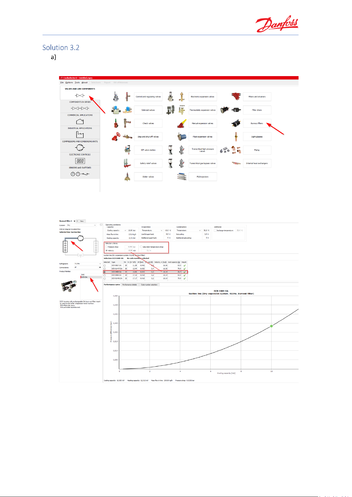
Open Coolselector®2; you will find that the program starts on the tab for ‘Valves and Line
Components’. From this screen, among the different component functionalities choose
“Burnout filters”.
Coolselector®2 creates a dry system by default, select the suction line and then click on
the DCR-DA in the product families. You will see the list of valid products and the best one
matching the selection criteria:
Here you can also see the other parameters for the filter in the table, such as the acid
capacity, as well as the pressure-drop as a function of changing the cooling capacity and
keeping the other parameters constant.
Page 19
Coolselector®2 Exercises
13
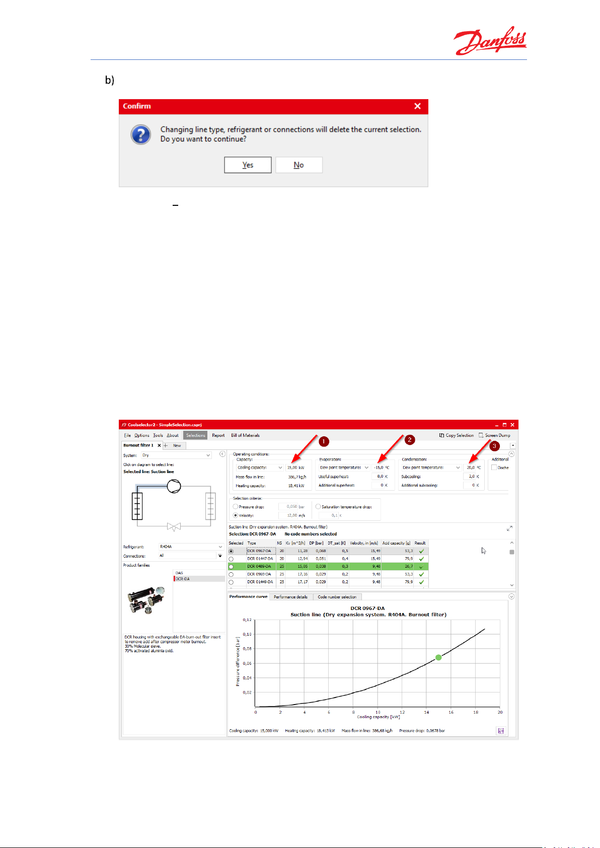
When you change the refrigerant, Coolselector®2 asks for a confirmation, as this would
mean creating a new selection procedure:
By clicking “Yes”, a new selection will be made. Note that, the ‘evaporation temperature’
and ‘condenser temperature’ are now changed to ‘dew point temperature’. This is since
R404A is a glide-refrigerant and hence it is required to have a reference for the evaporator
and condenser temperatures.
The current suggestion is “DCR 0967-DA”, which is different from the suggestion made by
the exact same properties in the system running with R134a; this is of course due to the
different properties of the two refrigerants.
Now you can proceed to changing the system properties. If you change them in the order
mentioned in the exercise, the suggestion will consequently be “DCR 01447-DA”, “DCR
0969-DA” and “DCR 0489-DA”.
Increasing the capacity would increase the mass flow in line and hence the speed in the
component, which results in a larger component. Decreasing the evaporation
temperature increases the mass flow-rate as the cycle COP would be lower. Decreasing
the condensation temperature has the opposite effect, which is the cause of the changes
in the suggestion.
As you noticed, the Coolselector®2 suggestion can change and can very easily be affected
by the system properties.
Page 20
Coolselector®2 Exercises
14
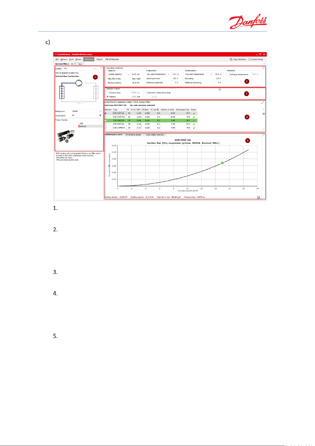
Once in the calculation and selection interface, you will find that the screen is separated in
different segments:
Segment “1” is dedicated to the application criteria for your selection. These criteria
include, but are not exclusive to, system type, line, refrigerant, connection type, and
product family.
Segment “2” is where you insert your system operating conditions, such as cooling
capacity, evaporation and condensation temperature, and useful superheat. These
operating conditions have significant impact on the calculations and a lack of due
care when filling them in might lead to inapplicable results. Whereas great care has
been taken to set meaningful default conditions, there is no guarantee that these
will mirror the operating conditions for your system design.
Segment “3” is dedicated to the product selection criteria for the suggestion to be
made in the next segment based on your inputs in functionality criteria and
operating conditions segments.
In segment “4” you will find the selection table. In this area you will see the options
matching the functionality criteria and operating conditions that you specified in
the selected family. For each calculation, Coolselector®2 has a ‘suggestion’ which
remains highlighted in green based on your input in the product selection criteria
input. The selection table also includes some of the most relevant information for
the product.
In segment “5”, you will find the performance details and information about the
chosen product from the previous segment. This information updates as you choose
other products from the list. The next part of this exercise gives some more
information about this segment.
Page 21
Coolselector®2 Exercises
15
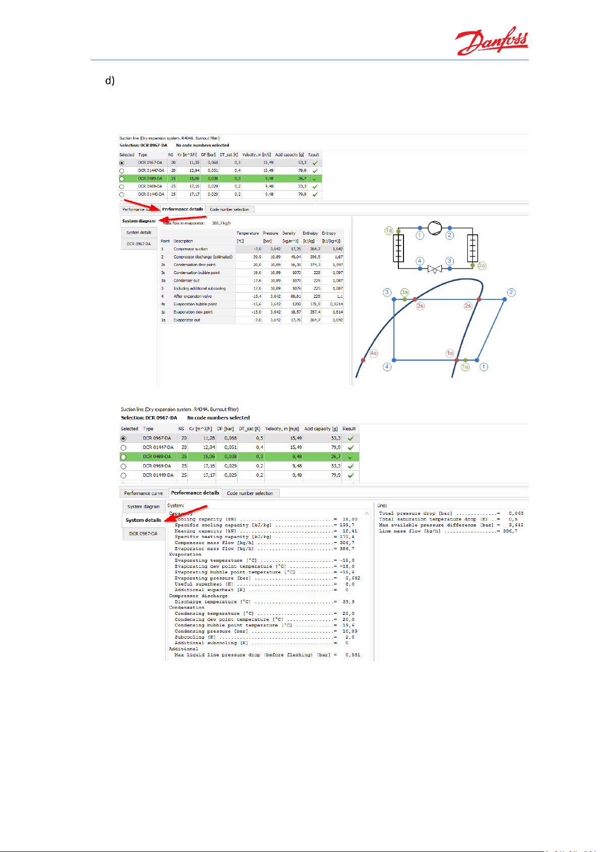
You can click on the performance details and check the system diagram calculations,
system details and the performance of the selected product from the list in the
corresponding tabs.
System diagram and different points calculations:
System calculation details:
Page 22
Coolselector®2 Exercises
16
Product performance details:
Notice, that the performance details are presented for any selected product and are not
limited to the suggested product. You can click on any of the products in the list and see
the calculations for the selected product.
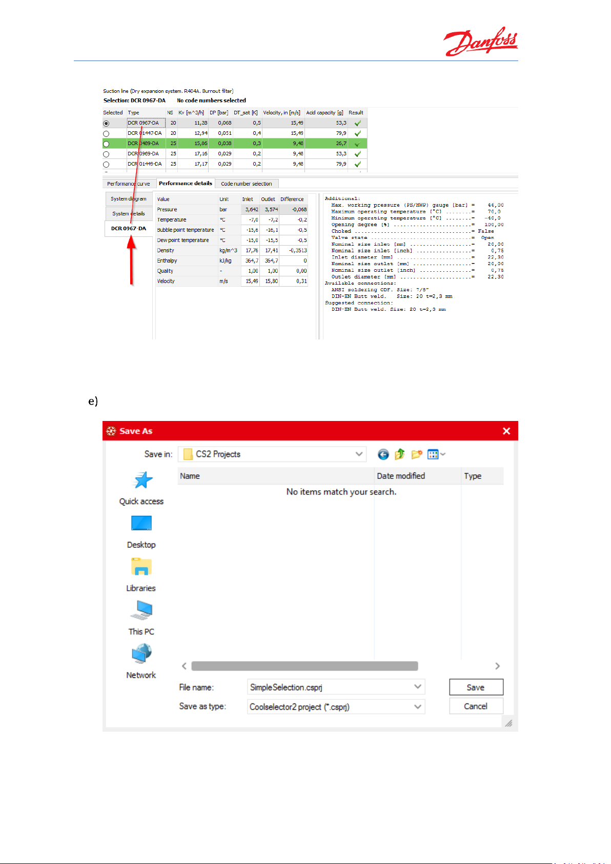
To save the project, open File | Save Project… or click “Ctrl+S” on the keyboard. You will
then be asked for the name and the location of the file:
You can also use the “Save Project As…” option to save it with a different name or “Save
and Send…” option to save and send it to a customer or a colleague.
Page 23
Coolselector®2 Exercises
17
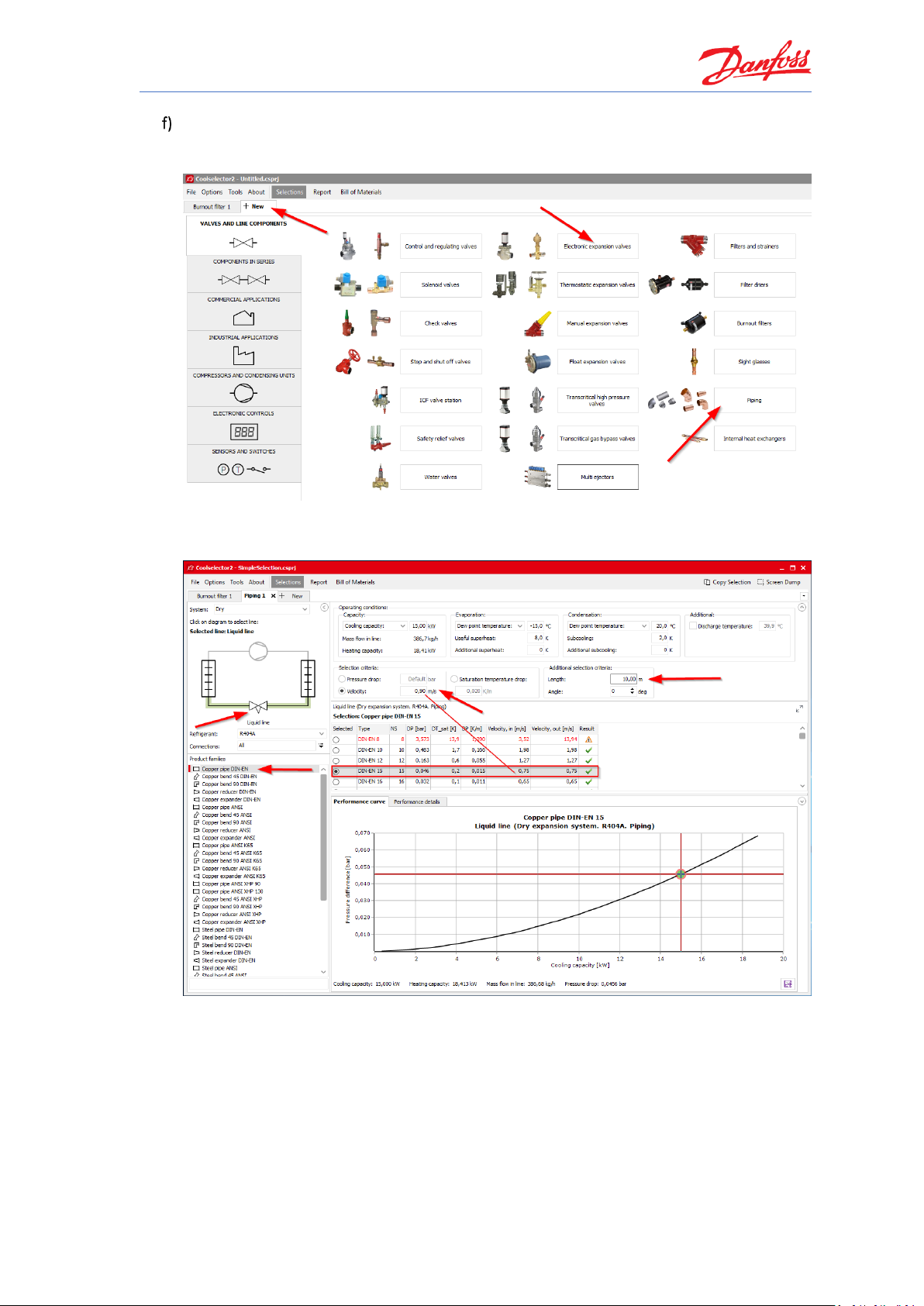
You can add a new tab for your new selection by clicking the “+ New” tab at the top
beside the tab for “Burnout filter 1”. The components, we need for the liquid line, are two
pipes and an expansion valve from the AKV family, which is an electronic expansion valve.
The suggested results would be:
Pipe before the expansion valve:
Note, that Coolselector®2 keeps your operating conditions for the system based on your
previous selection.
Page 24
Coolselector®2 Exercises
18
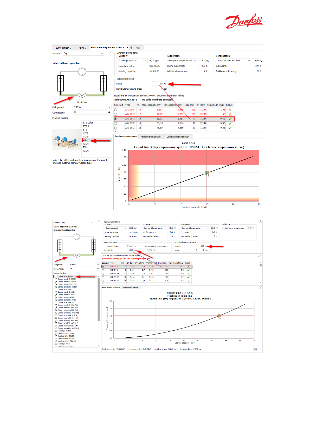
Electronic expansion valve:
Pipe after expansion valve:
Page 25

Coolselector®2 Exercises
19
As can be seen, the selected pipe to be placed after the expansion valve has a warning
“Flashing in liquid line”, which is due to flashing before the expansion valve.
Coolselector®2 always calculates the outlet conditions based on the inlet conditions.
Hence, by selecting a single component, which is going to be placed after other products,
in a line, the effect of the previous components in the line would be neglected. This effect
exists in every line; however, it is much more tangible in the liquid line since there is a
phase change after the expansion valve.
Comparing the product calculation results with the results from the system diagram
calculations, you can see that the inlet condition for all products is the condenser outlet
and the fact that the pipes cannot meet the outlet conditions required by the evaporator.
To overcome this, the inlet of each component should be the outlet of the previous
component. This is possible by using the components in series functionality, which we will
discuss in the next exercise.
Notice that the subcooling reference is the bubble-point temperature.
Page 26

Page 27

Coolselector®2 Exercises
21
Selecting components in series
Using information in System Properties 1 and Cycle Diagram 1:
Load the project you saved before selection of components in the liquid line in the
previous exercise. (If you saved it after that, simply close the tabs for the liquid line
components)
Create a new tab and repeat the selection process for all the components in the liquid
line, using the option “Components in Series”.
What is the difference between the two selection methods? Does the inlet and outlet
calculation results for each component match what was expected for the cycle diagram?
Can you change the selected component to improve the design? What is the share of each
component in the pressure drop of the line? What is the minimum and maximum capacity
which can be gained in this system using the selected expansion valve?
Save your project for the next exercises.
Page 28
Coolselector®2 Exercises
22
Selecting components in series
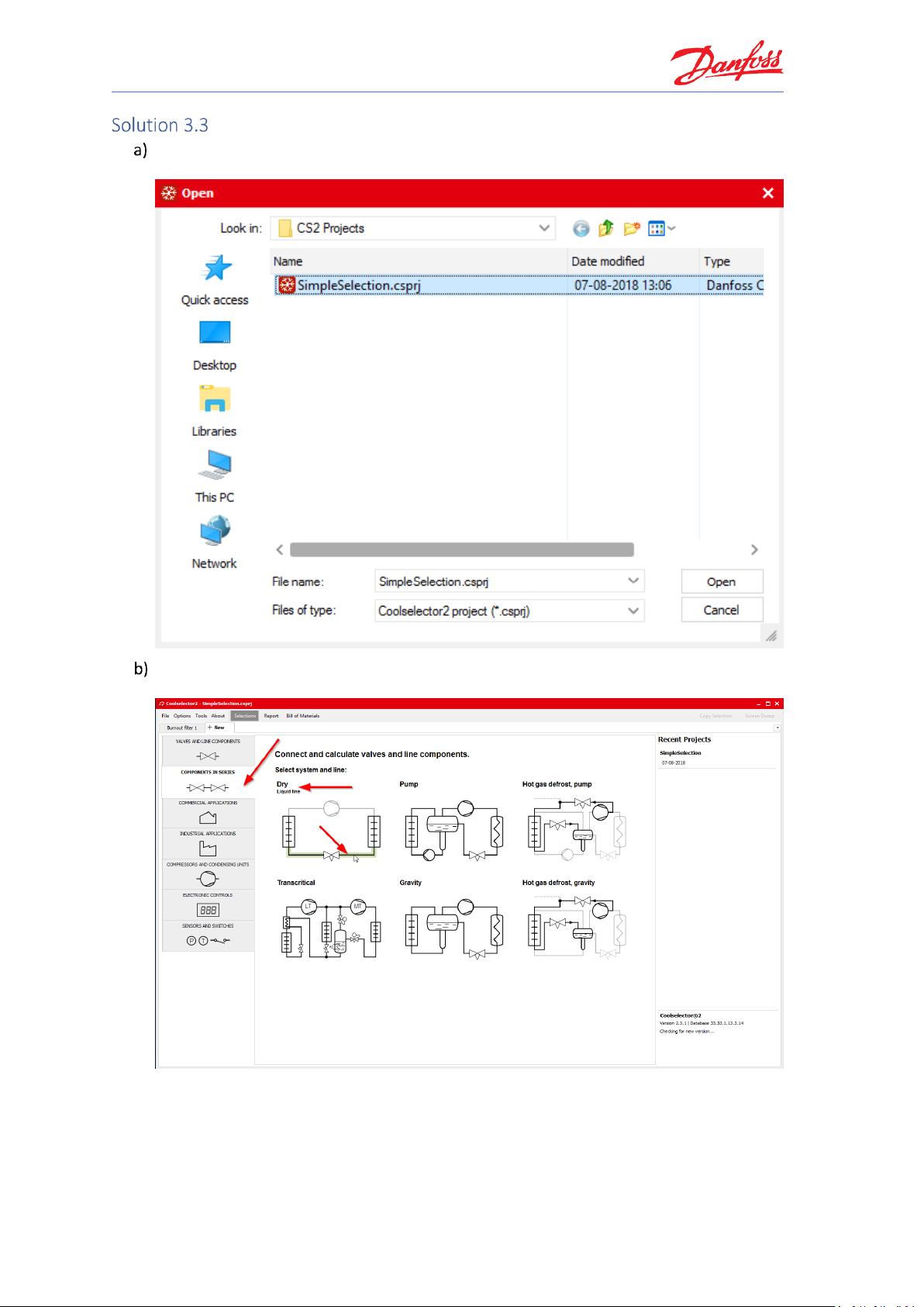
You can load the previously saved project from the menu File | Open Project… or by
clicking “Ctrl+O” on the keyboard.
Create a new tab and select the option “Components in Series” and then the liquid line in
a dry system:
Now, you need to add the components to the line. To do so, first, you need to select the
functionality you would like to add to the line, and then double click on the family or drag
the family and drop it in the location that you need it.
Page 29
Coolselector®2 Exercises
23
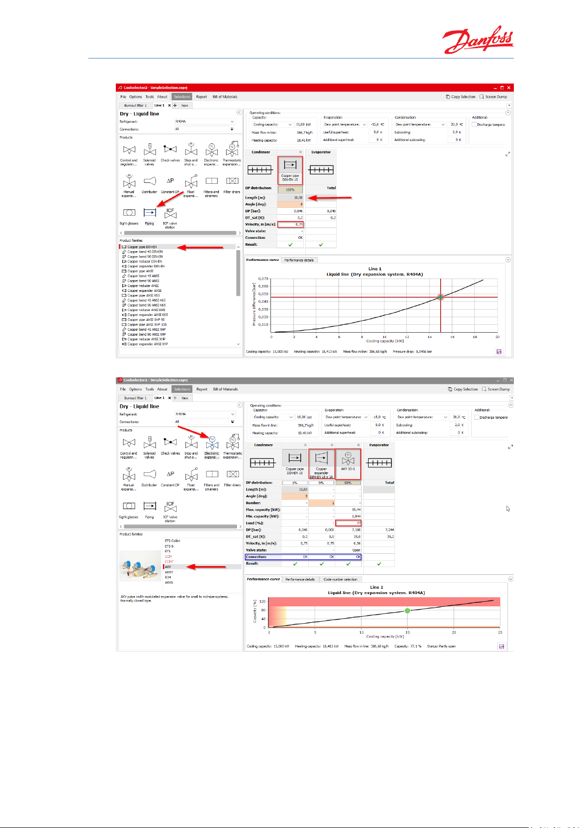
Add a copper pipe with DIN-EN connection to the line and set its length to one meter:
Now you need the AKV electronic expansion valve:
Notice that Coolselector®2 automatically added a “Copper expander DIN-EN 15 × 18”
between the two components. The software recognizes the material of the piping as well
as the connection sizes and standard between two components. When two connections
do not match, it adds the required expander/reducer between the two componets for
common cases, or informs you in the row shown by the blue triangle and you can fix the
connection problem manually by adding an expander/reducer from the proper family in
the piping function.
Page 30
Coolselector®2 Exercises
24
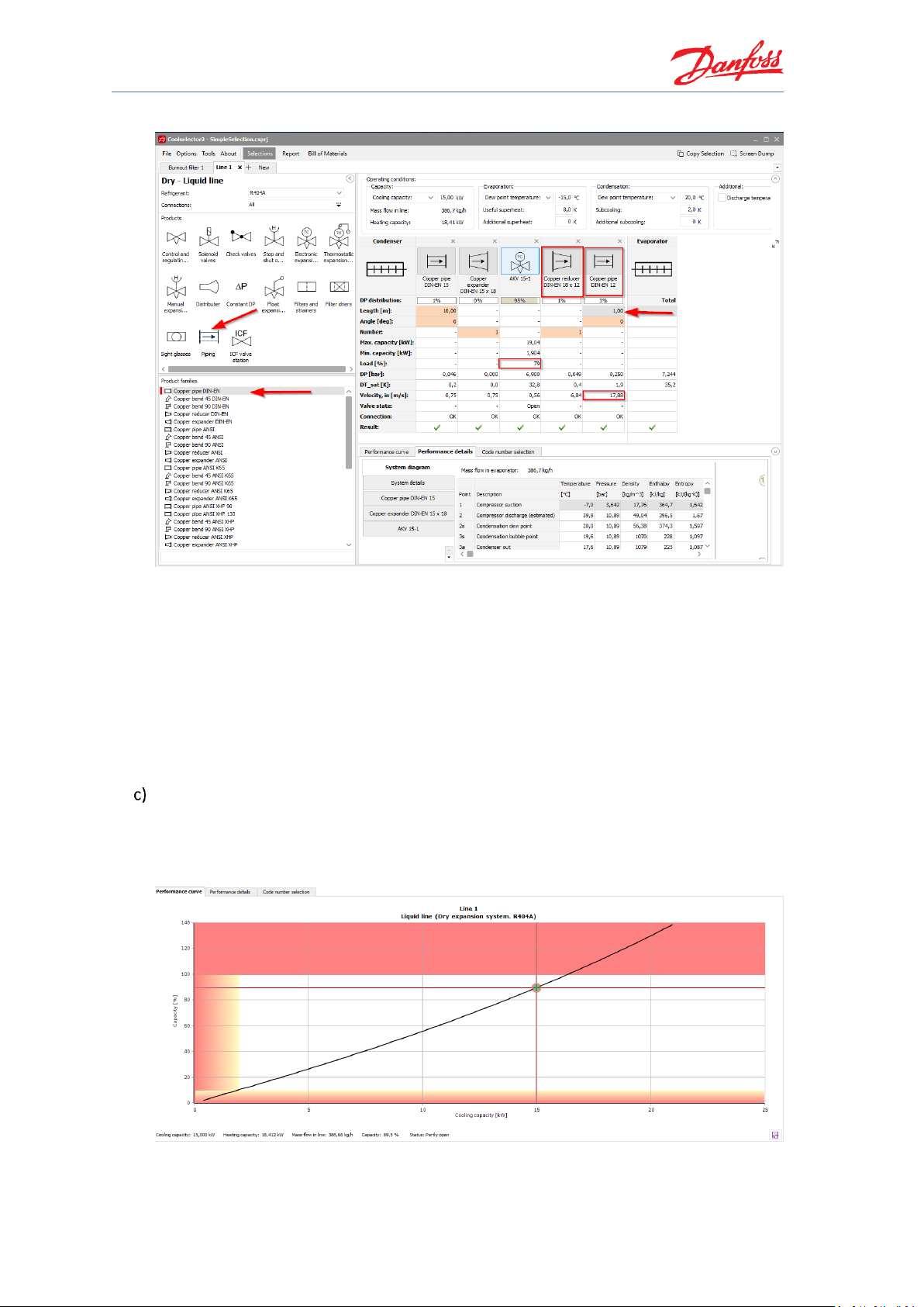
Now add the pipe after the expansion valve:
As can be seen, there are no warnings in the selected pipe anymore, since the expansion is
now happening in the expansion valve. It is also interesting to notice, that the load for the
AKV valve is increased. This is due to the fact that the added pipes after the valve increase
the pressure drop and hence the opening load of the valve will also increase. Additionally,
as can be seen, the target criteria for the pipe suggestion after the expansion valve are
clearly different to the one before the expansion valve.
Proper selection of AKV valves requires extra care, which we will discuss later in detail in
Error! Reference source not found.. Please be sure to check that before selecting an AKV v
alve.
Here Coolselector®2 calculates components one after another. Furthermore, you can see
the collective effect on the performance curve for the components in the liquid line and
the need for an expander/reducer if you want to select the suggested components. The
detailed calculation of each component with the right inlet condition as shown by
numbers 1-5 on the snippet can also be extracted.
Page 31
Coolselector®2 Exercises
25
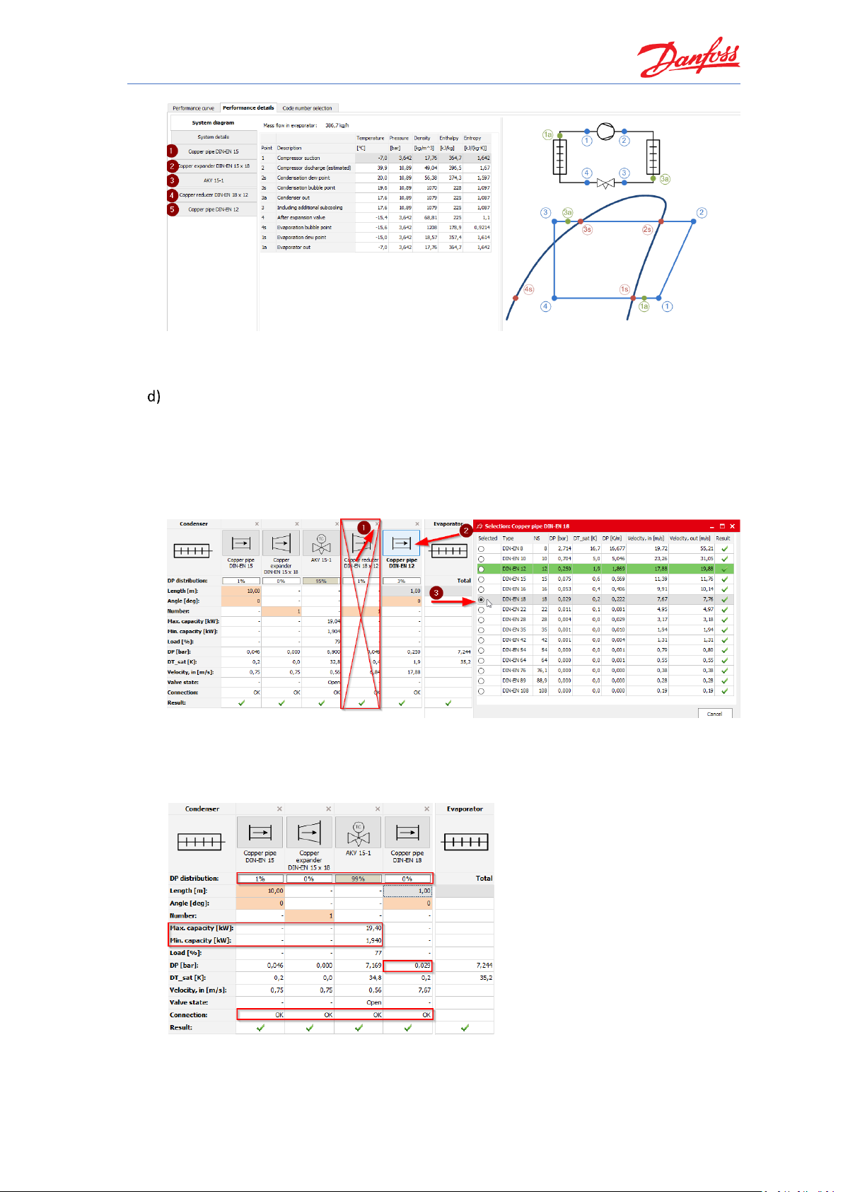
Note, that if you need to replace components in the line, you can do so by simply dragging
the component to the preferred position and dropping it there.
The suggestions for components in series calculation use the default selection targets and
values in Coolselector®2. However, if you want to select another component from the
same family, you can do so by clicking on the icon of the component in the line and
choosing the preferred one in the pop-up menu. In this case, as a good design practice, it
is better to avoid having a reducer after the expansion valve. To avoid having this, you can
simply remove the reducer using the close sign on the top right-hand side of the reducer
and select the size of the pipe which fits the expansion valve outlet:
You can see the share of each component on the pressure drop on top of the calculation
details. As you can see, the connections fit and, furthermore, the pressure drop after the
expansion valve is reduced significantly and is happening properly in the AKV valve. You
can also see the relevant calculation details such as min. and max. capacity in the details:
Page 32

Page 33

Coolselector®2 Exercises
27
Understanding superheat and selecting a compressor
Using System Properties 1 and Cycle Diagram 1:
Select a compressor for the system using the following requirements. Which compressor
does Coolselector®2 suggest as the best choice for this cycle?
1. Application: Refrigeration
2. Power supply: 50 Hz
3. Refrigerant: R404A
4. All compressor types
5. Fixed speed
Can you explain the importance of superheat and the difference between useful and
additional superheat?
Now, set the additional superheat to 5 K. Does it change the suggested compressor? Can
you explain why it is important to provide the additional superheat correctly? Change the
superheat back to the previous value.
What is the COP of the suggested compressor at the working conditions? Save the project
for the next exercise.
Page 34

Coolselector®2 Exercises
28
Understanding superheat and selecting a compressor
Create a new tab and choose the option compressors and condensing units. Then select
“Compressors”:
Check that the operating conditions are as mentioned in System Properties 1:
Set the application criteria as they were specified in the exercise:
Page 35

Coolselector®2 Exercises
29
Coolselector®2 suggests the MLZ058T4:
The suggested compressor can achieve the requirement for this cycle and match the
demand. You can check the match in the last column in the selection segment. To show
the relevant details for this exercise, the columns shown for the selection segment are
different from the default ones. If you want to know how you can change this, check out
Exercise 1.1.
Some superheat is required for the refrigerant at the compressor inlet to ensure
avoidance of liquid droplets in the compressor.
The useful superheat is the superheat inside the evaporator, which contributes to the
cooling capacity. However, a very high useful superheat decreases the evaporator
efficiency as well as the density at the evaporator outlet which results in higher
compressor consumption. This value is set to 8 K by default in Coolselector®2.
Additional superheat happens after the evaporator in the suction line. A longer length of
the suction line would result in a higher additional superheat. This is set to zero by default,
as it is highly affected by the length and size of the suction line, which is not provided in
Coolselector®2. However, you should try to provide an accurate value or estimation for a
good selection.
If you change the additional superheat to 5 K, the suggested compressor will change to
MLZ058T2, which allows a slightly higher volumetric flow rate to support the given cooling
capacity.
The reason is that increasing the useful superheat would result in a decrease of density
after the suction line at the compressor inlet. The mass flow rate required for the cooling
capacity would be the same (you can check that in the performance details tab), but a
lower density means a higher volumetric flow rate, which results in demand for a slightly
larger compressor. Another important aspect regarding additional superheat is the
discharge temperature, which can be affected significantly, and which would affect
selection of components in the discharge line, as well as compressors or condensing units.
Hence providing additional superheat correctly is important for proper selection and
suggestion.
Page 36

Coolselector®2 Exercises
30
You can check the details of the compressors in the list in the performance tab in the
product performance and information segment. To check the COP at the working
conditions, choose the performance tab, then select the COP. Now you can check the COP
for the compressor on working conditions:
You can also check the COP at the exact working condition in the selection segment:
Page 37

Coolselector®2 Exercises
31
Selecting electronic controllers
Now, we would like to add a controller to our system. Our system, Cycle Diagram 1, is a single
compressor system with an AKV expansion valve.
Select a case controller with the following requirements:
1. Expansion Valve Type: EEV AKV
2. Number of Compressors: Single compressor
3. Communication: MOD bus
Which controller(s) does Coolselector®2 suggest?
If we would like to have a system with “Dual case sections” as a future update, which
controller(s) can you select?
Page 38

Coolselector®2 Exercises
32
Selecting electronic controllers
Create a new tab and choose the option “Electronic controls”. Then select “Case
controllers”:
If you apply the requirements in the selection criteria segment, Coolselector®2 will
suggest the controllers that can satisfy the requirements:
You can add the “Dual case sections” requirement in the “Refrigeration System” section:
Page 39

Coolselector®2 Exercises
33
Creating a report, bill of materials and code numbers
Now, after going through the selections and calculation phase, we will create a report and get
the bill of materials for our selections. For this exercise, load the project including burnout filter
selection, the components in series selections for the liquid line, the compressor and the
controller, then:
Check the report for your selections:
1. Then try adding your name to Coolselector®2, so it appears automatically on the
reports. Add a project name to the report.
2. Add component performance details for the burnout filter and the cooling capacity
curves for the compressor to your report.
3. Try exporting the report as a PDF file.
Select the code numbers for different components on each tab and then:
1. Check the bill of materials for your selections.
2. Include piping in your bill of materials.
3. Export your bill of materials as an Excel file.
Page 40

Coolselector®2 Exercises
34
Creating a report, bill of materials and code numbers
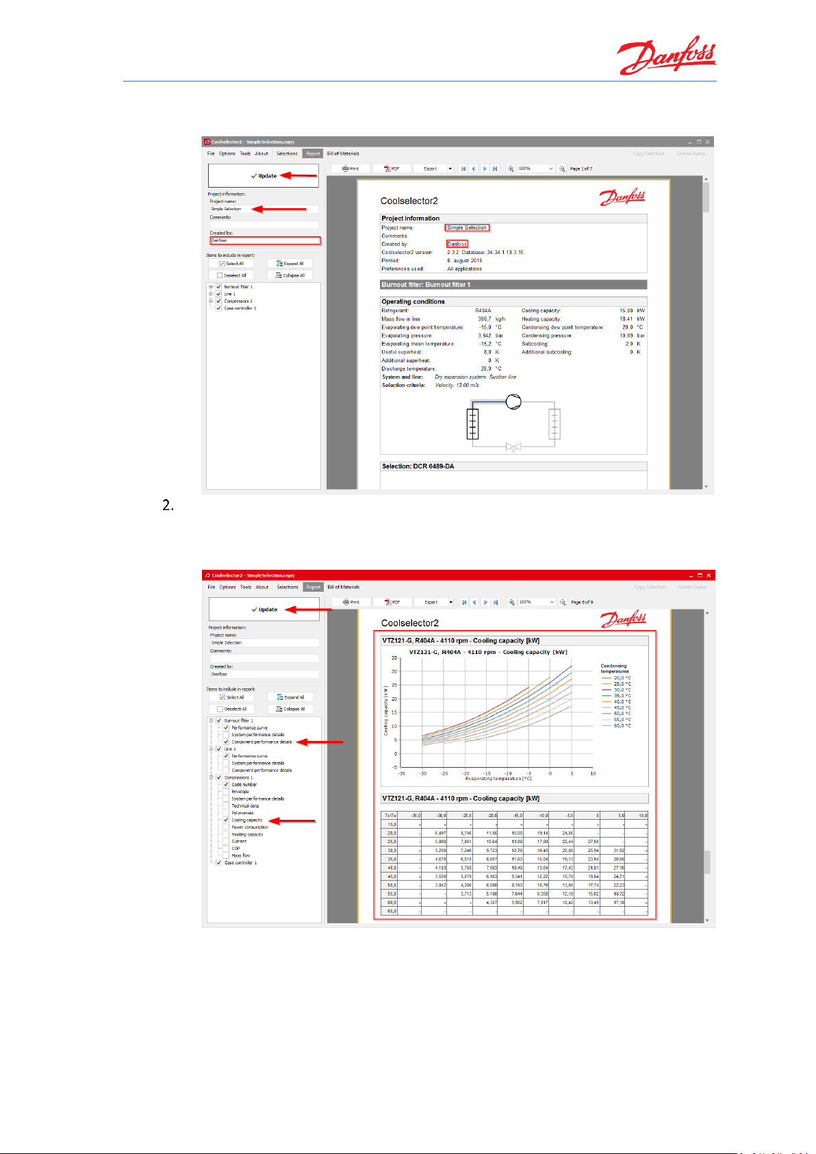
Check the report by clicking on the “Report” in the menu bar of Coolselector®2. This
opens the report section. The segment for the project information will be blank if you did
not enter this information before:
To add your name to Coolselector®2, open “Options | User, Language and Country
…” and then add your name and click “OK”
Page 41
Coolselector®2 Exercises
35
Now, your name should be on the report preview section. You can also add a
project name. After that, click on “Update” to update the report preview:
You can add/remove included information in the report. To do so, click on the “+”
sign beside each list to see the available options, or click on the “Collapse all
button”. Add the required fields requested by the exercise and click update and
check the result. Note that each list belongs to one tab on your “Selections” section:
Page 42

Coolselector®2 Exercises
36
Click the “PDF” button at the top of the report preview to export your report as a
PDF. You have multiple options for your exported PDF, such as printing specific
pages in the report, adding extra information, or securing your pdf file with a
password. Investigate those options for further details.
You will then be asked for the name and the location of the document and you can
click “Save”. If you selected the option “Open after export”, the report will then
automatically open.
Coolselector®2 enables you to select the relevant code numbers for the selected products.
Depending on the product type, the code number(s) can be accessed/modified differently.
In the current document, go to the “Selections” section by clicking on the “Selections”
button in the menu bar.
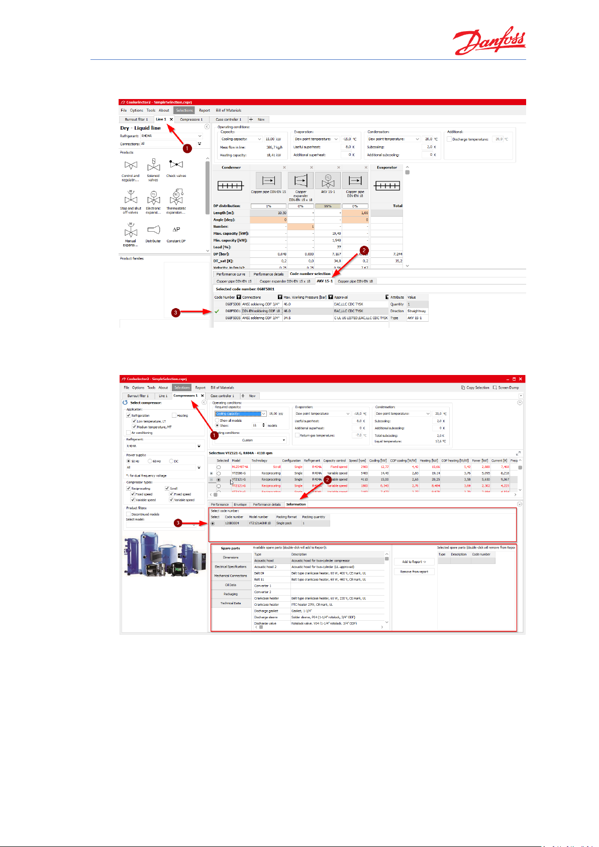
Go to the tab for “Burnout filter" and select the tab for “Code number selection” and
select the proper casing and filters. E.g. we would like to have the DIN connection casing
with copper connection to match our installation and a pack of 8 filter cores:
Page 43
Coolselector®2 Exercises
37
Then, go to the tab for liquid-line calculation and select the code number for the AKV
valve. E.g. we select the one with DIN-EN connection to match our selection:
Now, for the compressor code number, you need to go the “Information” tab, where you
can select the code number and also see other information about the compressor,
including the available spare parts:
Page 44

Coolselector®2 Exercises
38
And for the case controller the code number is visible after you click on your selected
controller:
1. To check the bill of materials after the selection of code numbers, you just need to
click on the “Bill of materials” button in the menu bar:
Page 45

Coolselector®2 Exercises
39
2. To include the piping, just click on the option “Include piping”:
3. To export the bill of materials as an Excel file, click on the “Excel” button at the top
of the bill of materials preview. Then specify the destination and the name for the
exported file:
Page 46

Page 47

Coolselector®2 Exercises
41
Changing predefined preferences and customizing the interface
What is the equivalent of operating conditions in different unit systems? Change the unit
system to American units.
Set the preferences to commercial applications. Check the changes that happened in the
default interface of the new tab. Is there any difference in the option for selection of
“Valves and Line Components”? Then go back to all applications again.
Modify the selection table for compressors:
1. Remove the columns after “Mass flow”.
2. Replace “Heating” column with COP cooling.
Resize the segments in the current session for the burnout filter:
1. Minimize the operating conditions segment. Then maximize it again.
2. Resize the product performance and information section.
3. Expand the selection table and performance and information section to full screen.
Page 48
Coolselector®2 Exercises
42
Changing predefined preferences and customizing the interface
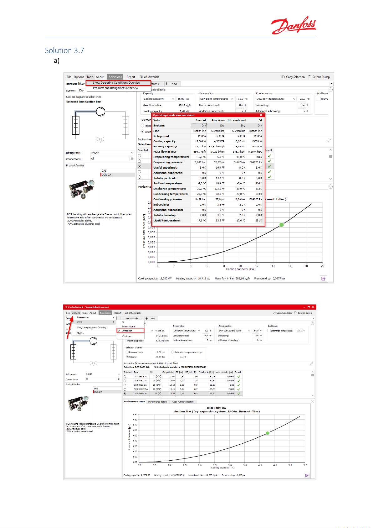
You can select the “Tools | Show operating conditions” menu and see the equivalent of
your operating conditions in different unit systems:
To change the unit system to American units, you simply need to select it in “Options |
Units | American”:
Page 49

Coolselector®2 Exercises
43
You can set the preferred application to commercial applications in “Options |
Preferences | Commercial applications”:
You will notice that the “+ New” tab interface has changed in terms of product sort order
as well as the available options. This is to provide a better environment for you as the
user. You can customize the options to further match your requirements, this is
somethingwe will discuss that in the next exercise.
You can see that some of the options, which are more specific to industrial applications
are now missing from the “+ New” tab interface, such as “ICF valve station”:
Page 50

Coolselector®2 Exercises
44
Go to the tab for your selected compressor. You can modify which columns you see in
your selection table and also change the order of the calculations and selections made in
the “Valve and Line Components” option as well as “Compressors”. To do so, right click on
the table header and select “Manage Columns…”. This is step 1 and 2 in the following
snippet:
To remove the columns after the “Mass flow”, you can simply uncheck them in the
list as shown by step 3.
To replace “Heating” with “COP cooling”, you should click on “Heating” and then
click on the top arrow as shown by steps 4 and 5.
Then you can click OK to update the table. Coolselector®2 will remember your
modifications next time you run it, and you can always go back to the default table by
clicking on the default setting:
Page 51

Coolselector®2 Exercises
45
You can also resize different segments or minimize the segments to see the information
more clearly. Coolselector®2 will remember previous modifications mentioned in this
exercise, but sizes will reset to default when you start Coolselector®2 again.
You can minimize the “Operating conditions” segment by clicking on the button at
the top right-hand side of the segment:
To resize any of the segments, you can click and drag on the border to see
information more easily:
Page 52

Coolselector®2 Exercises
46
After setting the general criteria and operating conditions and the product
suggestion criteria, sometimes, it is handy to expand the segments for the selection
table and product performance and information to full-screen. You can do that by
clicking on the expand button in the top right-hand corner of the selection table:
Page 53
Coolselector®2 Exercises
47
Changing the advanced settings
Create a custom preference for the selection you made in this chapter by going to “Options |
Preferences | Edit preferences” and then:
Select “Dry expansion system” as the default system for your custom preference. Then
enable “Valves and Line Components”, “Components in series”, Compressors and
Condensing Units” and “Electronic Controls” as the available product pages.
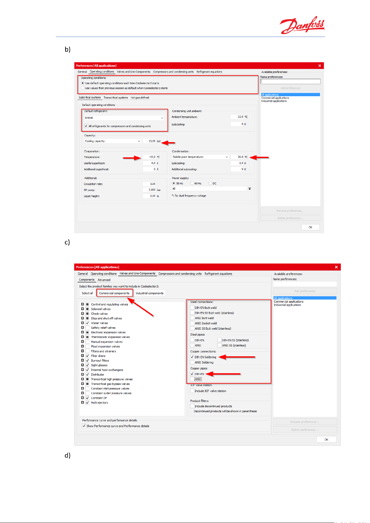
Go to the “Operating conditions" tab and change the refrigerant and default values for
subcritical systems to match the information in System Properties 1.
Go to the “Valves and Line Components” and select “Commercial components”. Then
remove all connections except for “Copper DIN-EN”.
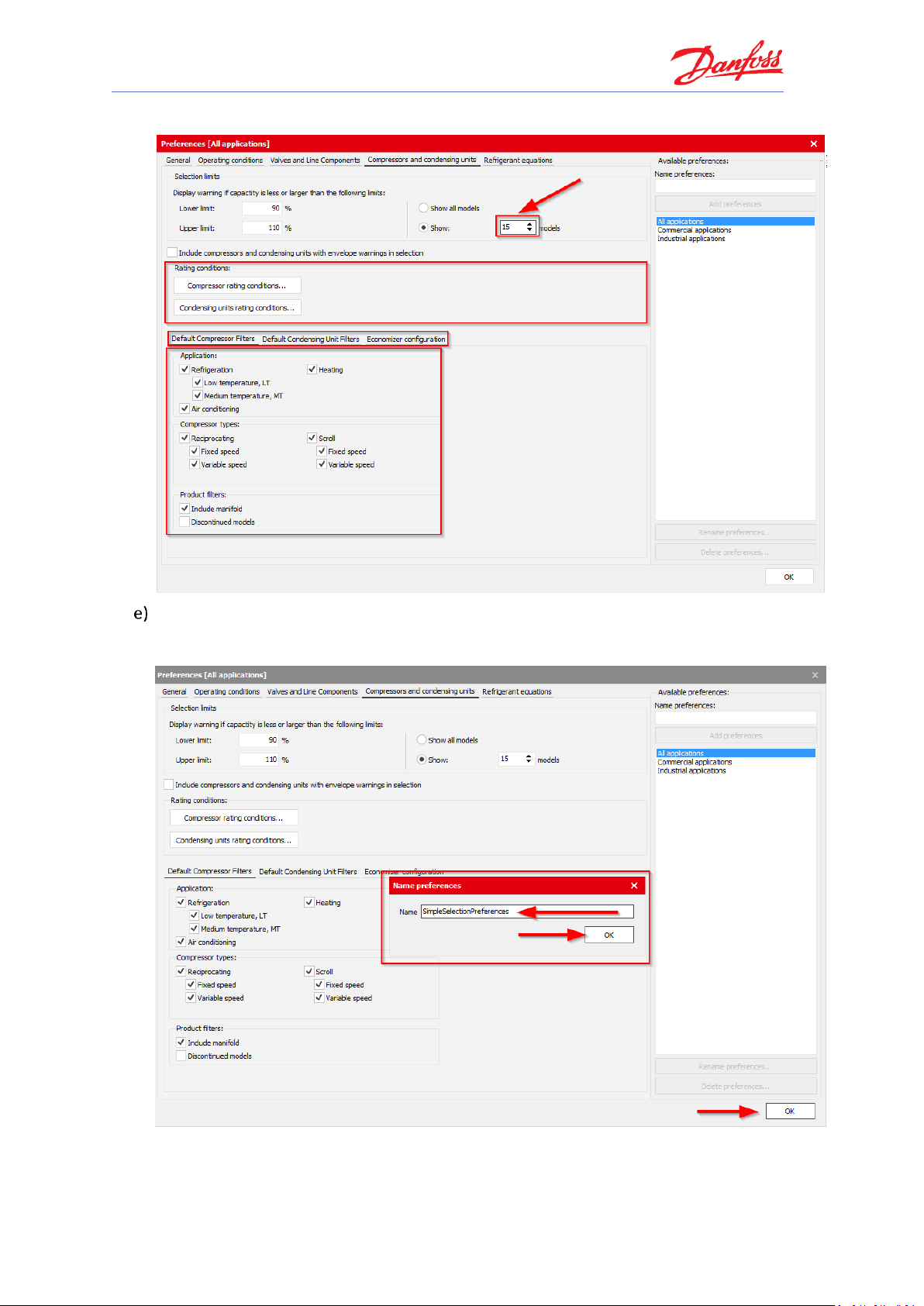
Go to the “Compressors and condensing units” and change the number of models to show
to 15.
Save your preferences to use them later.
Can you change the default length of the pipes?
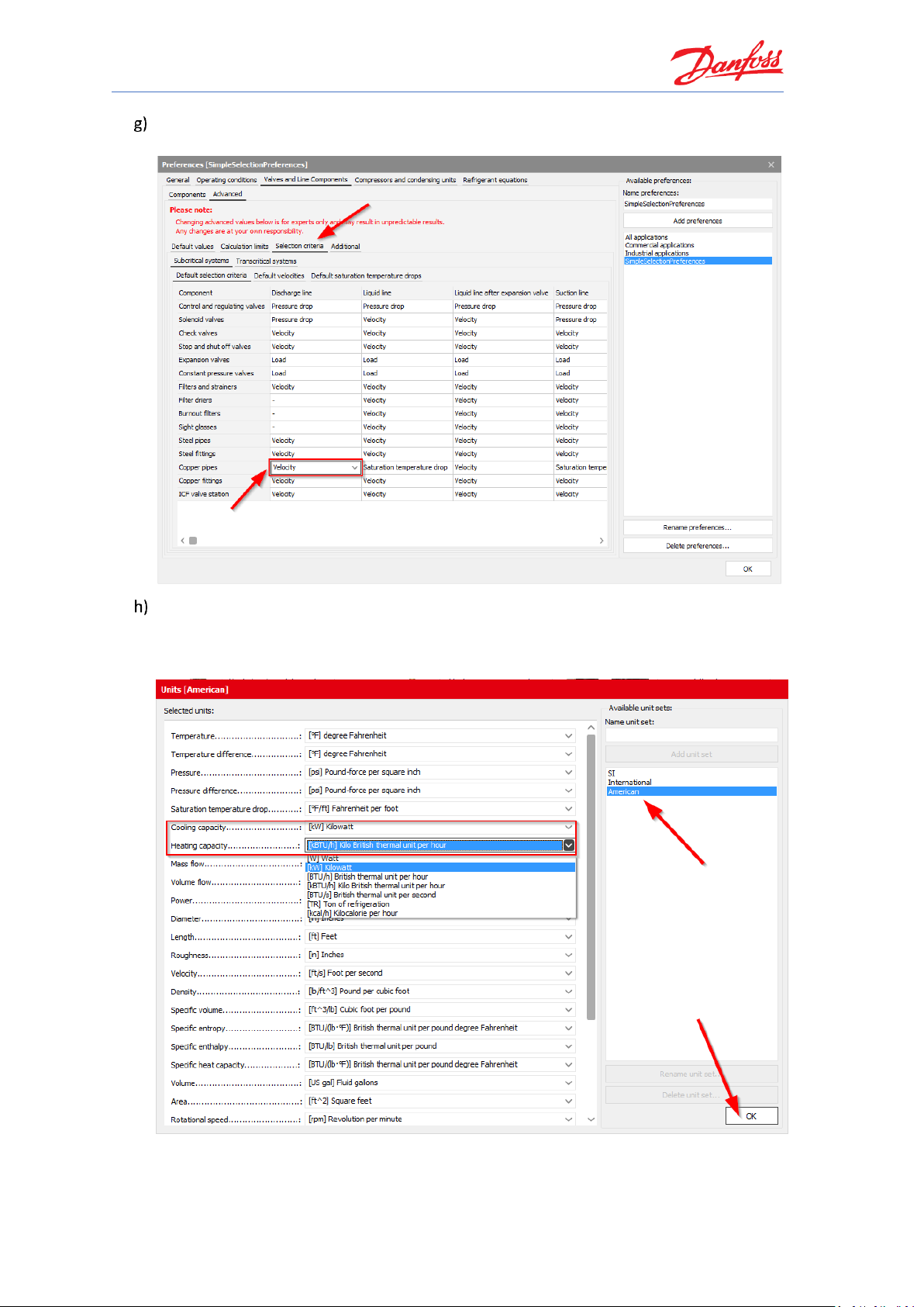
Can you change the default selection criteria for the “Copper pipes” in the discharge line
to velocity?
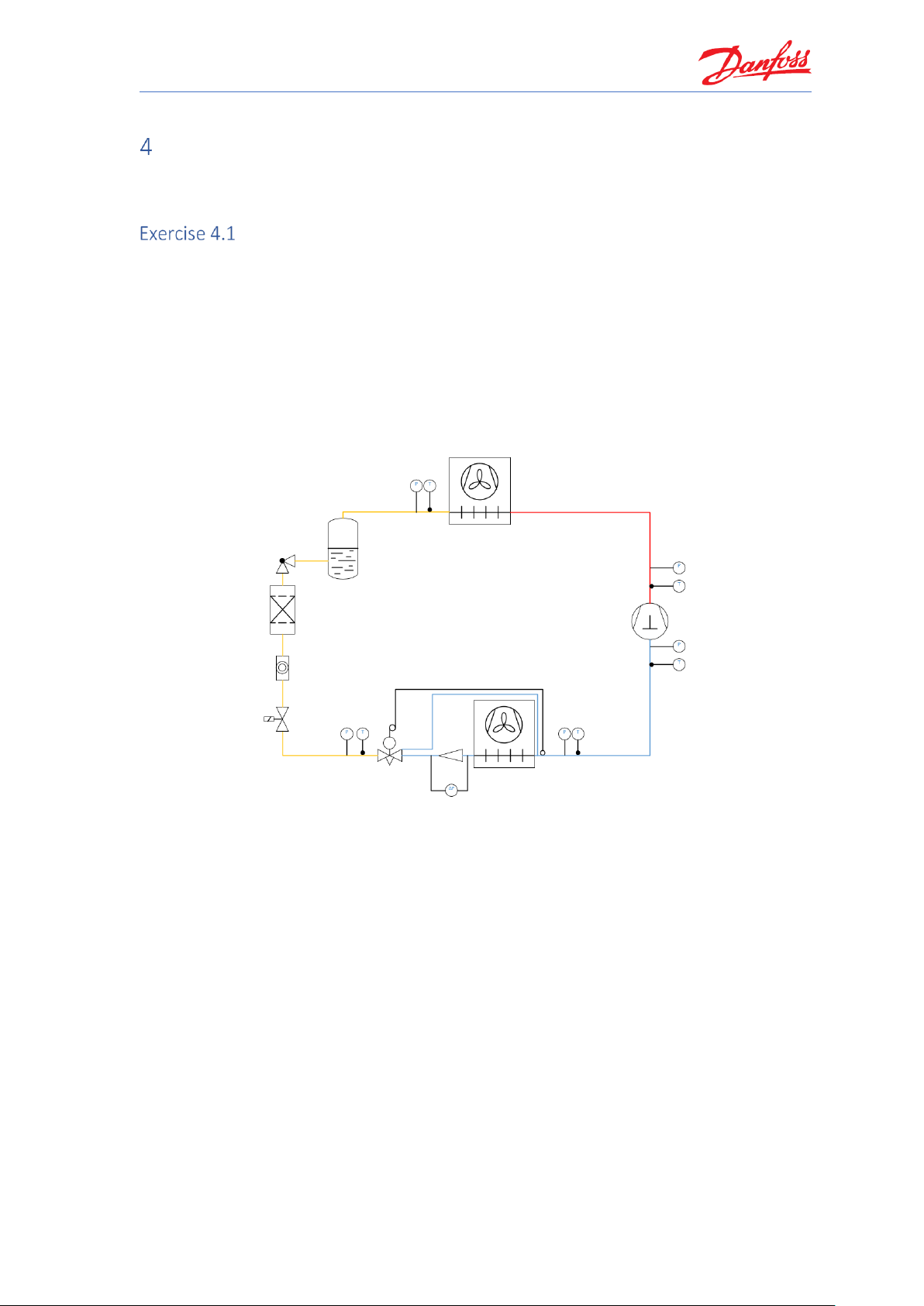
Can you create a custom unit system for your special needs based on American units but
using kilowatts as the unit for the cooling and the heating capacity?
Page 54

Coolselector®2 Exercises
48
Changing the advanced settings
The settings we discuss in this exercise do not need to be modified in most cases, since we, in
the Coolselector®2 team, constantly strive to optimize the default preferences based on our
customers’ requirements. However, the advanced settings enable you to customize and improve
your experience and even modify the calculations if you see a necessity to do so. To create
custom preferences, use “Options | Preferences | Edit preferences…”:
You will see the “Preferences” window. On top you have the different preferences that we
will try to cover briefly in this exercise. Feel free to investigate further and explore your
other options. You can select “Dry expansion systems” among the options for the “Default
system” and add/remove options for your selection and calculations among the product
pages and also sort their order in the interface:
Page 55
Coolselector®2 Exercises
49
Then you can go to the “Operating conditions” tab by clicking on the top bar and changing
the default operating conditions:
Now, you can go to the “Valves and Line Components” tab and select the type of
components you would like to see for your selections/calculations and the families in each
functionality, as well as connection sizes and some more options:
In the tab for compressors and condensing units, you will find the relevant settings for
those products. You can choose which products to see and even see the rating conditions
as well as create custom ones. You can also set the limits to those that you prefer. For this
Page 56
Coolselector®2 Exercises
50
exercise, we just want to change the number of models to show in the selection table:
If you click the “OK” button to apply your settings, Coolselector®2 will ask you to name
your preferences and save them. Coolselector®2 will keep the default settings intact so
you can always easily go back to the predefined preferences:
Page 57

Coolselector®2 Exercises
51
Next time you open Coolselector®2, it will keep your preferences and you can see that in
the list of the preferences. You can come back to this menu and edit, rename or delete
your preferences at any time.
You can also see that the new tab menu has changed based on your new preferences.
And on the top right-hand side of the window, you will be able to see the recent projects
and load them easily.
Please note that changing the following settings can affect the results of the selection or
calculation process and lack of due care can have a negative effect on the suggestions and
default calculations. However, when necessary, the advanced settings can be changed,
but it is suggested to avoid such changes and to revert them to the default values when
there is no need to change them.
The default values for the calculations can be changed in “Valves and Line Components |
Advanced | Default values” in the preferences window. For this exercise, we want to
change the default length of the pipes to 5 meters instead of 10 meters:
Page 58
Coolselector®2 Exercises
52
The selection criteria for all the components supported by Coolselector®2 can be found in
“Valves and Line Components | Advanced | Selection critera”:
To create a custom unit system, you need to go to “Options | Units | Custom…”. Then you
will find the unit used for each of the default unit systems, and you can create your own.
For the unit system for this exercise, we need to select the American unit system first and
then change the unit for the cooling and the heating capacity:
By clicking OK, you will be asked to save your custom unit system and give it a name. It will
then appear on the list of unit systems similar to your custom preferences.
Page 59
Coolselector®2 Exercises
53
Commercial applications
For exercises in this chapter, you can set your preferences to commercial applications through
“Options | Preferences | Commercial applications”.
Selecting a thermostatic expansion valve
Select a TU thermostatic expansion valve for a dry expansion system with R448A with the
following operating conditions:
• Cooling capacity: 2.5 kW
• Evaporator dew point temperature: -8 °C
• Useful superheat: 8 K (Default)
• Condenser bubble point temperature: +45 °C
• Subcooling: 3 K
• Load: 100%
• Distributor pressure drop: 1.0 bar
a) Which valve is suggested by Coolselector®2?
b) What is the nominal capacity of the suggested valve?
c) Is it possible to run the system at 20 °C condensation temperature with this valve size?
d) What is the load at 45 °C and 20 °C, respectively?
e) What is the load a TXV should typically be selected at?
Page 60

Coolselector®2 Exercises
54
Selecting a thermostatic expansion valve
With a commercial refrigeration system, we usually talk about a dry expansion system. So, in
Coolselector®2, you first set the System to ‘Dry’ and then select the Liquid line:
Next, please select the refrigerant (R448A) and the product family (TU/TC):
Afterwards, type in the operating conditions:
The operation (system) condition values are required to calculate the mass flow circulating
through the expansion valve. Part of this information is the pressure losses between the
condenser outlet and the valve inlet, as well as the pressure drop between the outlet and the
evaporator inlet. Those pressure drops are reflected in the value of “Distributer dp”. The
pressure drop across the valve therefore is equal to pc – (pe + dp distributer).
Page 61

Coolselector®2 Exercises
55
The suggested valve is a TU orifice size 5 (TU - 5):
The suggested valve has a nominal capacity of 2.541 kW:
Yes, it is possible to run the valve at +20 °C condensation temperature. To prove this in
Coolselector®2, change the bubble point temperature of condensation to +20 °C:
You will now see that TU – 5 is no longer the suggested best match by Coolselector®2,
however, it is still in the list with a warning that the capacity of the expansion valve is too
small:
A thermostatic expansion valve has a nominal capacity at a defined opening superheat,
but with higher opening superheat a higher capacity is given. However, typically, such a
valve can be used up to 150% of its nominal capacity. Due to that, a TXV has a so-called
“over capacity”, which is indicated by the Performance diagram with a curve that does not
end at 100% nominal capacity:
Page 62

Coolselector®2 Exercises
56
Since the valve, for a limited period of time, would run at the higher load, it is not the
recommended selection in Coolselector®2. However, in reality, the valve is an option.
At 45 °C condensation the load is about 98% and at 20 °C condensation the load is about
110% of the nominal capacity.
45 °C:
20 °C:
A TXV should never be oversized but should be selected at 100% of its nominal capacity.
To reach the required working superheat built in to the system, the static superheat
should be re-adjusted rather than oversizing the valve. In this way, the bandwidth will be
utilized better and the valve will work with higher stability.
Page 63
Coolselector®2 Exercises
57
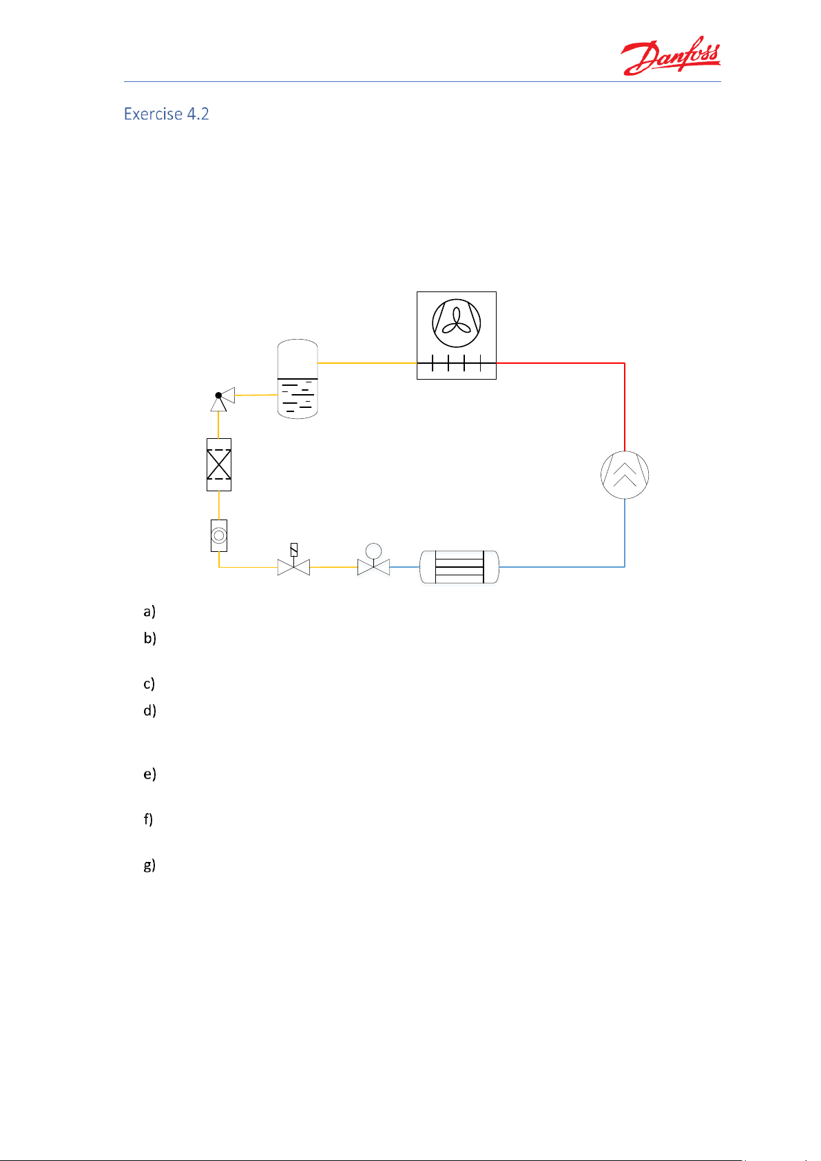
Selecting an electronic expansion valve
Select an electronic expansion valve for a chiller, from the product family ‘ETS Colibri®’, with the
following operating conditions:
• Refrigerant: R513A
• Cooling capacity: 90 kW
• Evaporator temperature: 3 °C
• Useful superheat: 8 K (Default)
• Condenser temperature: +40 °C
• Subcooling: 3 K
M
M
Which target load should be put in the selection criteria and why?
Which valve size will be recommended for that target load (if you have chosen a range for
the load, use the upper limit of the range for this input)?
What is the velocity at the valve inlet for the suggested valve?
Is there an alternative to the valve suggested by Coolselector®2 in the selection list with
the same load at nominal conditions? What is the difference between the two valves and
why is there a difference? Please explain.
Please explain, what is the minimum possible capacity and opening degree for the valve
suggested by Coolselector®2 in b)?
Would there be a risk if you select ETS Colibri 100C electronic expansion valve? Please
explain using a chiller application as an example.
What would be the suggested valve if we want to replace the valve with one from the AKV
family?
1. What is the difference between the two families, ETS and AKV?
2. What would be the actual speed at the inlet of the suggested expansion valve?
Page 64

Coolselector®2 Exercises
58
Selecting an electronic expansion valve
Similar to the previous exercise, set the system to ‘Dry’ and then select the liquid line. Next,
please select the refrigerant (R513A) and the Product Family (ETS Colibri):
Afterwards, change the operating conditions as requested by the exercise:
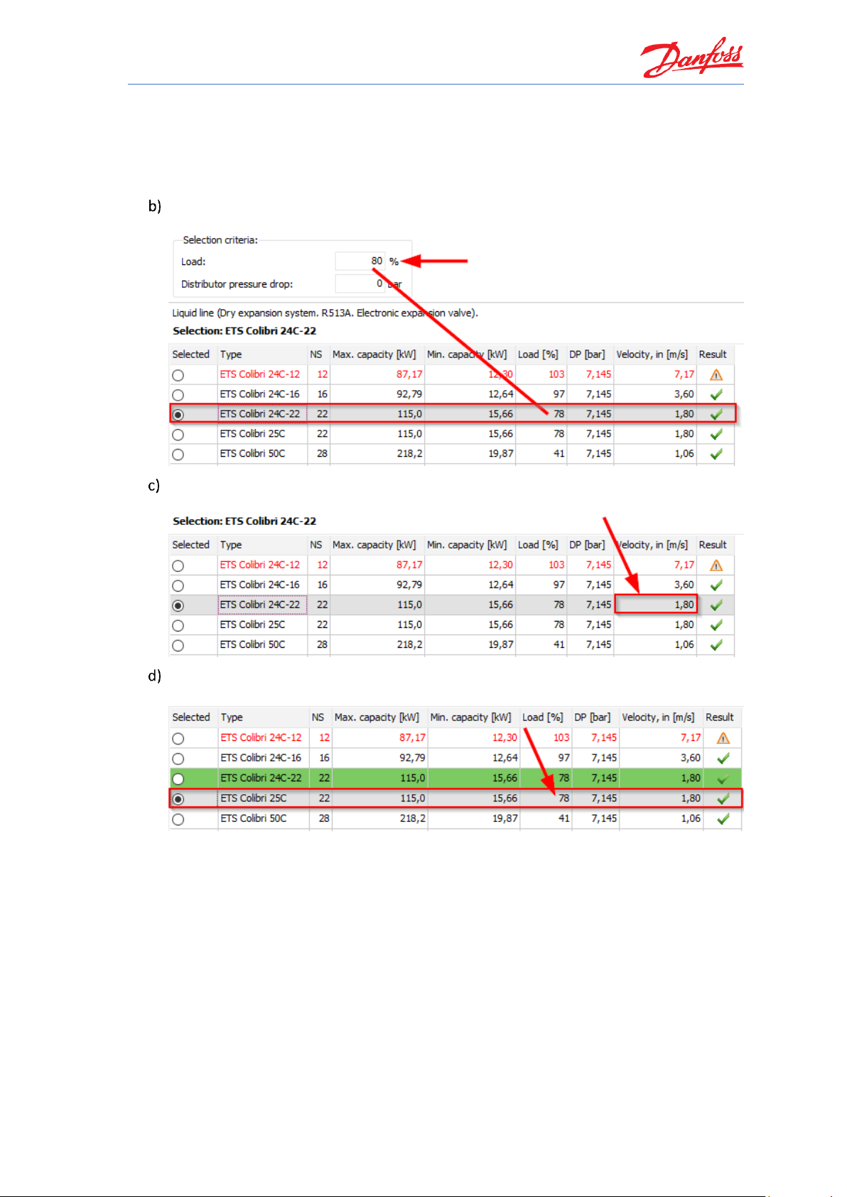
For both air condition and refrigeration systems, the recommended selection criteria for
‘load’ is about 70% to 80%. By setting the load like this, there is 20% to 30% capacity left,
for example for pull-down.
Page 65
Coolselector®2 Exercises
59
As is evident, the more over-capacity the system requires, the lower the load should be
set in the selection criteria.
For low temperature applications it is recommended to size the electronic expansion valve
at 50-60%. Otherwise, the pull-down capacity might be insufficient.
Based on the selection criteria and a load set to 80%, Coolselector®2 suggest the ETS
Colibri 24C-22 as the best match:
The liquid velocity at the inlet connector is about 1.80 m/s. You can find the liquid velocity
in the selection table:
An alternative would be the ETS Colibri 25C, since this has the same load percentage
(78%) as the ETS Colibri 24C-22:
The ETS Colibri 24c-22 and the ETS Colibri 25C valves are exactly the same in performance,
which you can see in the calculation results. The only difference is that ETS Colibri 25C is
equipped with a side glass, while ETS Colibri 24C-22 does not have the side glass.
You can contact Danfoss or your supplier for more information or if you have any
questions regarding the products and you require assistance with your selection.
Page 66
Coolselector®2 Exercises
60
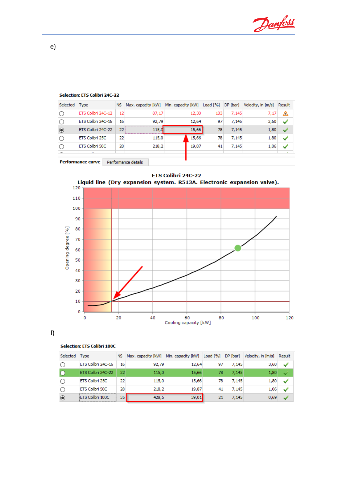
The minimum capacity for the ETS Colibri 24C-22 at the given operating conditions is
15.66 kW at around 10% opening of the valve. You can find the minimum capacity in the
selection table.
Furthermore, you can see this in Coolselector®2 if you use the performance curve shown
underneath the selection table. Move your mouse to the desired cooling capacity [kW] on
the x-axis to see the corresponding opening degree [%] on the y-axis:
ETS Colibri 100C has a higher max capacity of about 428.5 kW, as is evident from the
selection table in Coolselector®2:
This would be more than enough capacity for running the system under full load
conditions as well as pull-down. However, in the event that the chiller runs into part load,
the size of the ETS Colibri 100C might become an issue since its minimum possible
capacity is 39.01 kW. Thus, the ETS Colibri 100C may be too large for this system.
Page 67

Coolselector®2 Exercises
61
As is evident from the example above, it is always recommended to verify if the valve is
suitable for the whole envelope of the system, considering both loads and extreme
conditions.
To replace the valve with one from the AKV family, we need to click on the AKV in the
“Product families” list:
If you don’t change the operating conditions, you will notice that Coolselector®2 keeps the
previous inputs for operating conditions. The suggested valve would be AKV 20-2 in this
case:
AKV is a family of pulse width modulated expansion valves. This means the valve is
either fully open or fully closed. As a result, while the valve is open, the capacity is
the maximum capacity.
To calculate the actual velocity for AKV or any of the pulse width modulated
expansion valves, you should replace the capacity to the maximum capacity of the
valve. You will see that for AKV 20-2 the velocity at the inlet would be 0.73 m/s:
Page 68

Page 69

Coolselector®2 Exercises
63
Selecting a solenoid valve
Please select an EVR v2 solenoid valve for a liquid line of a chiller application with an electronic
expansion device. For safety reasons, a solenoid valve shall be installed in front of the expansion
valve. Please use the following operating conditions:
• Refrigerant: R513A
• Max cooling capacity: 45 kW
• Evaporator temperature: 0 °C
• Useful superheat: 4 K
• Condenser temperature: +42 °C
• Subcooling: 2 K
• Cooling load: 40% to 100%
M
M
Which solenoid valve does Coolselector®2 suggest as the best fit for the system
requirements under the given operating conditions?
What is the capacity range of the system using the suggested valve?
Please explain what should be considered in relation to the cooling load when selecting a
failsafe component for a system matching these operating conditions.
Taking your conclusions from the previous parts into consideration, is the valve suggested
by Coolselector®2, at these operating conditions, the best fit for the system
requirements? If not, which valve should be chosen instead and why?
What is the pressure drop in the solenoid valve?
What is the maximum possible pressure drop without getting flash gas in front of the
expansion device?
Please explain what the limits are for a solenoid valve placed in a liquid line.
Page 70

Coolselector®2 Exercises
64
Selecting a solenoid valve
Select the solenoid valve from the “Valves and Line Components” and then set the System to
‘Dry’ and choose the Liquid line. Then select the refrigerant (R513A) and the product family (EVR
v2).
Afterwards, type in the operating conditions:
The solenoid valve suggested as the best match for the system under these operating
conditions is the EVR 20:
At 100% cooling load the capacity is 45 kW, as specified in the operating conditions. You
can also verify this in the “Performance details | System details”:
Thus, at 40% cooling load, the capacity will be 18 kW.
In relation to the cooling load, it is important to consider that the system design supports
a continuous change of cooling load from 100% down to 40% of its nominal capacity, as
stated in the operating conditions. When selecting a component, please take this into
careful consideration, in order to ensure that the solenoid valve will work failsafe across
the entire application envelope.
Page 71

Coolselector®2 Exercises
65
Taking your previous conclusions into consideration, it is evident that the EVR 20, as
suggested by Coolselector®2 for the full load condition, is not suited for the system with
the given operating conditions.
Looking at the performance curve, the valve is poorly suited for cooling capacities of less
than 39.547 kW:
A better fit for the system with the given operating conditions and a continuous change of
cooling load from 40-100% and thereby capacities ranging from 18 kW to 45 kW would be
the EVR 10, which supports capacities starting as low as 14.497:
As is evident from the performance curve, the EVR 10 supports the entire application
envelope of the proposed system. If you change the load to the minimum from the given
operating conditions (18 kW) and check the suggested valve again, you will notice that
Coolselector®2 suggests “EVR 10”. So, make sure you check the full range of capacity or
other varying parameters to improve your selection.
Page 72

Coolselector®2 Exercises
66
From the performance curve we can conclude that for the EVR 10, at 45 kW the pressure
drop is about 0.2889 bar, whilst at 18 kW the pressure drop is 0.0462 bar.
45 kW (0.2889 bar):
18 kW (0.0462 bar):
The maximum pressure drop without getting flash gas in front of the expansion device is
0.569 bar. The value can be found under ‘Performance details | System details’:
Page 73

Coolselector®2 Exercises
67
Most of the Danfoss solenoid valves are so-called “servo operated” and need a minimum
pressure drop (by the mass flow through the valve) to be in a stable open position.
Thus, for a solenoid valve in a liquid line, the limits are: sub cooling, no creation of flash
gas and minimum pressure drop. If one (or more) of those limits has been reached, it will
turn the result in Coolselector®2 red and a warning will come up to inform you that the
valve is not well suited for the system under the given operating conditions.
Exact warning texts can be read by resting the mouse pointer over the warning icon within
Coolselector®2:
Page 74

Page 75
Coolselector®2 Exercises
69
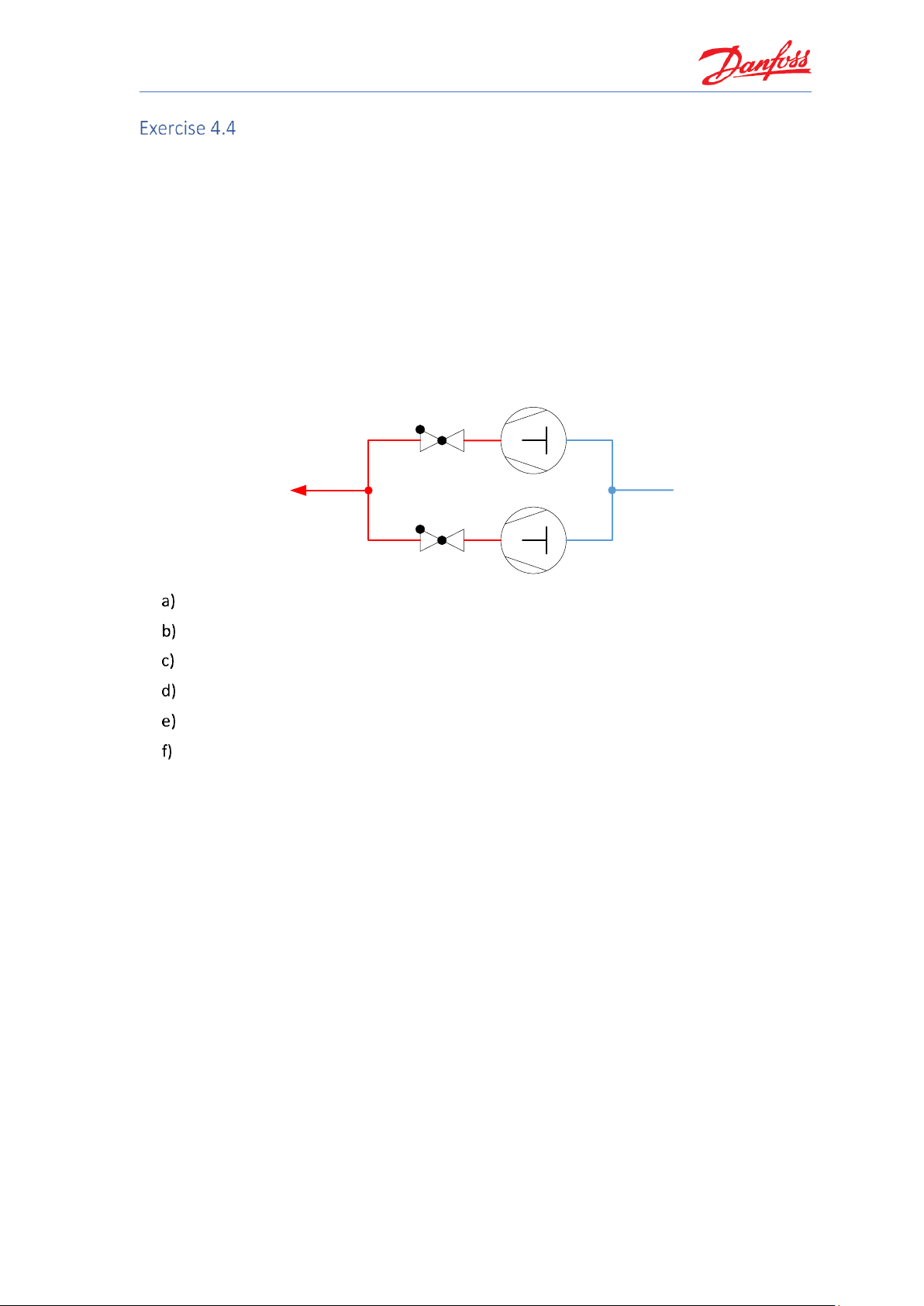
Selecting a check valve with reciprocating compressors
Using the following operating conditions for the discharge line of two circuits with semihermetic reciprocation compressors working in parallel and a small power pack. First, please
explain which check valve version should be selected (NRV or NRVH)? Then check the exercises
for the following operating conditions:
• Refrigerant: R513A
• Cooling capacity: 45 kW
• Evaporator temperature: -10 °C
• Superheat: 8 K
• Superheat suction line: 4 K
• Condenser temperature: +42 °C
• Sub cooling: 2 K
Which check valve version does Coolselector®2 suggest as the best match?
What is the pressure drop across the valve?
What is the minimum required pressure drop to fully open the valve?
What is the possible system part load?
What is the minimum capacity to keep the valve fully open?
What is the suggested connection size?
Page 76

Coolselector®2 Exercises
70
Selecting a check valve with reciprocating compressors
Selection of check valves at the discharge of a compressor needs very special attention.
Depending on the compressor type and application, slightly different results may occur.
If a power pack’s compressor is cut off, the check valve will protect against returning gas from
the discharge line back into the cylinders of the compressor.
Due to mechanical vibrations, in this particular situation, it could happen that a check valve with
a standard spring cannot keep the port tightly closed. If this happens, the refrigerant could
return into the cylinder and in a worst-case scenario, it could condensate, thereby forming a
liquid. When the compressor is next started, its valve place will be damaged, and it will break
down.
Apart from mechanical vibrations, reciprocating compressors tend to create gas pulsations. The
reason for this is the principal of compressing gas in one stack and releasing it into the discharge
line within an extremely short time. With each release, a peak called a “gas pulse” will be
generated. Depending on the design and number of cylinders in the compressor, the effect can
vary. Generally speaking, the greater the number of cylinders, the smoother the running will be
and fewer pulses will be generated.
As a result of the above, two types of Danfoss check valves are available:
• NRV with a standard spring
• NRVH with a stronger spring.
Since the compressors in question in this example are semi-hermetic, it can thus be concluded
that to ensure the tight closure of the port, and to prevent the refrigerant from returning to the
cylinder, the check valve with the stronger spring (namely the NRVH) should be selected.
Now, please set the proper system, refrigerant and operating conditions in check valve selections
based on the given conditions and as explained in the previous exercises.
Based on the above input, Coolselector®2 suggests the NRVH 22:
The pressure drop across the valve is 0.484 bar:
The minimum required pressure drop to open the valve is 0.3 bar:
Page 77

Coolselector®2 Exercises
71
The possible system part load is 26%. Reading in the selection table, the load (in percent)
is 126%. With this in mind, you can now calculate the possible system part load:
The minimum capacity required to keep the valve fully open is 36 kW. You reach this
figure by looking at the performance curve and finding the area which is not red or yellow
(partly open valve). The point on the x-axis where the white area starts marks the capacity
limit required to keep the valve fully open:
You find the suggested connection size by going to “Performance details | NRVH 22” and
then looking under “Additional”. The correct result here is 28 mm (1 1/8”):
Page 78

Page 79
Coolselector®2 Exercises
73
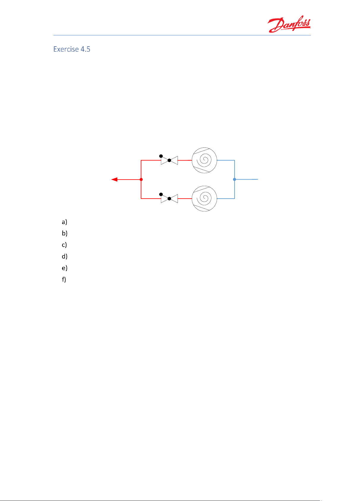
Selecting a check valve with scroll compressors
Using the following operating conditions for the discharge line of two circuits with scroll
compressors working in parallel and a small power pack: Please explain, which check valve
version should be selected (NRV or NRVH)? The operating conditions are:
• Refrigerant: R513A
• Cooling capacity: 45 kW
• Evaporator temperature: -10 °C
• Superheat: 8 K
• Superheat suction line: 4 K
• Condenser temperature: +42 °C
• Sub cooling: 2 K
Which check valve version should be selected?
What is the pressure drop across the valve?
What is the minimum required pressure drop to fully open the valve?
What is the possible system part load?
What is the minimum capacity to keep the valve fully open?
What is the suggested connection size?
Page 80

Coolselector®2 Exercises
74
Selecting a check valve with scroll compressors
A hermetic scroll compressor works smoother than a reciprocating compressor when
compressing the gas, which means fewer mechanical vibrations are created.
In addition, the top shell of the scroll compressor acts as a muffler, due to the relatively large
volume, and it will smoothen the remaining gas pulsations.
Keeping the explanation from the previous exercise in mind, it is evident that without the impact
of mechanical vibrations and with smoother gas pulsations, check valves with standard springs
(NRV) can be used in most cases where the compressor is a hermetic scroll.
Please set the appropriate system, refrigerant and operating conditions for check valve
selections based on the given conditions and as explained in the previous exercises.
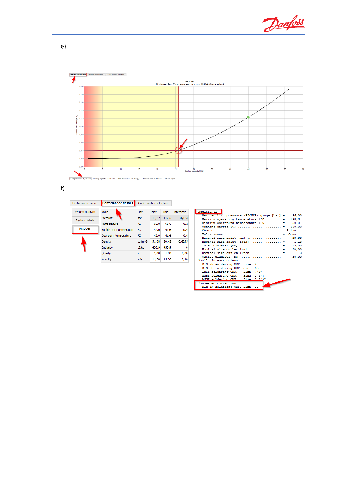
Based on the above input, Coolselector®2 suggests the NRV 28:
The pressure drop across the valve is 0.123bar:
The minimum required pressure drop to open the valve is 0.04 bar:
The possible system part load is 75%. Reading in the selection table, the load (in percent)
is 175%. With this in mind, you can now calculate the possible system part load:
Page 81
Coolselector®2 Exercises
75
The minimum capacity required to keep the valve fully open is 25.875 kW. You reach this
figure by looking at the performance curve and finding the area which is not red or yellow
(partly open valve). The point on the x-axis, where the white area starts, marks the
capacity limit required to keep the valve fully open:
You find the suggested connection size by going to “Performance details | NRVH 28” and
then looking under “Additional”. The correct result here is 28 mm (1 1/8”):
Page 82

Page 83

Coolselector®2 Exercises
77
Selecting a check valve for the condenser line
Please explain, which type of Danfoss check valve (NRV/NRVH) should be used for the situation
where a check valve is added to the condenser line to avoid charge migration from the receiver
to the condenser during longer standstill periods of the compressors e.g. overnight, during the
winter period or similar. Please, also include an explanation as to whether the check valve
should be fully opened or if it can run as partly open under the following operating conditions:
• Refrigerant: R513a
• Cooling capacity: 45 kW
• Capacity control: Two compressors = 50% / 100%
• Evaporator temperature: -10 °C
• Superheat: 8 K
• Superheat suction line: 4 K
• Condenser temperature: +42 °C
• Sub cooling: 2 K
Which check valve version and size should be selected for the system under the given
operating conditions?
For which capacity should the valve be selected and why?
What is the pressure drop across the valve?
What is the minimum required pressure drop?
What is the saturated temperature drop and what does it mean?
What is the suggested connection size and what is the velocity?
Would the next larger valve also work?
Page 84

Coolselector®2 Exercises
78
Selecting a check valve for the condenser line
Since no mechanical vibrations or pulsations happen in the condenser line, a check valve with a
standard spring (NRV) can be used. Also, due to the fact that there are no vibrations or
pulsations, using a partly open condition is possible (down to the minimum pressure drop).
Please set the proper system, refrigerant and operating conditions in the check valve selections
based on the given conditions and as explained in the previous exercises.
Based on the above input, Coolselector®2 suggests the NRV 22 (standard spring):
The valve should be selected at the most critical load, which in this case is part load.
Afterwards, the 100% system load should be verified to check if this is also ok, and to
ensure that no pressure/temperature drop, which is too high for the capacity of the valve,
will occur.
The pressure drop across the valve at part load (22.5 kW) is 0.021 bar.
The pressure drop across the valve at full load (45 kW) is 0.026 bar:
The minimum required pressure drop is 0.02 bar. Below this value, the valve becomes
unstable.
Page 85

Coolselector®2 Exercises
79
The saturated temperature drop is 0.1 K.
It is the pressure drop converted into saturated temperature. Usually at the outlet of
condenser, only a little subcooling of the liquid is given. Thus, in the condenser line, it is
important to keep the pressure/temperature drop as low as possible to avoid flash gas.
You find the suggested connection size by going to “Performance details | NRV 22” and
then looking under “Additional”. The correct result here is 22 mm (7/8”):
You find the velocity also under “Performance details | NRV 22”. The correct result here is
1.11 m/s:
Page 86

Coolselector®2 Exercises
80
The next size in NRVs is the NRV 28. According to Coolselector®2, this valve is also suitable
for the required operating conditions. However, looking closer at this valve, it is evident
that the part load pressure drop is almost equal to the minimum pressure drop needed
before the valve becomes unstable. Thus, it might not be the best choice for this system
due to the lack of safety margins.
Part load pressure drop = 0.20 bar:
Full load minimum pressure drop = 0.20 bar:
Page 87

Coolselector®2 Exercises
81
Selecting an evaporation pressure control valve for a one-to-one
system
We would like to guarantee that the temperature in the evaporator of our system will not go
below a specific value. This can be done by controlling the different system conditions such as
avoiding that the goods freeze. Let us assume that the evaporator is connected to a condensing
unit with a fixed speed compressor and the system runs with the following operating conditions:
• Refrigerant: R134a
• Cooling capacity: 1 kW
• Evaporator temperature: 4 °C with a minimum of 0 °C
• Condenser temperature: +40 °C (summer conditions)
PC
TC
a. Avoiding system failure, which effect(s) or condition(s) can make such a system run at a
lower evaporation temperature?
b. At the position specified by the red circle in the diagram above, which kind of valve can
be used? What is the parameter that the valve controls?
c. What is the appropriate control valve “offset” to keep the evaporation temperature to a
limit of 0 °C?
d. Which size control valve should be used? What are the possible impacts to the system
based on your choice of a specific control valve?
Page 88

Coolselector®2 Exercises
82
Selecting an evaporation pressure control valve for a one-to-one
system
The system will run in balance (meaning, without system failure) at the design condition
only if the surrounding conditions remain static compared to the design conditions both at
the evaporator and the condenser.
1. If the ambient temperature drops, the condensing temperature decreases and
hence the cooling capacity increases. This will result in a lower evaporation
temperature.
2. If the evaporator inlet temperature drops below the design value (e.g. an air
conditioning taking fresh air in from outdoors), the evaporation temperature
decreases.
3. Reducing the air flow rate results in the evaporator running at part load and hence
the required capacity will also be lower than the capacity provided by the
compressor. This also causes a balance point at a lower evaporation temperature.
The pressure control has to be towards the evaporator, i.e. the valve should control
evaporator outlet pressure. A “KVP” valve is suitable for the capacity range and function.
To calculate the offset a step-by-step process should be followed:
The evaporation temperature change needs to be converted into saturated
pressure change. Like all mechanical pressure control valves, the KVP will change its
opening degree if the pressure changes. This change is called ‘a proportional band’
or ‘offset’, if only referring to the move from a closed position to a certain open
position.
The value for this offset can be entered in Coolselector®2.
Step 1: Offset
Utilizing the evaporation input field in Coolselector®2, we get the following values
for evaporation pressure and thus, we can calculate the allowed offset for the valve:
• 4 °C = 3.378 bar
• 0 °C = 2.929 bar
• dT = 4 K; pressure change/Offset: 3.378 bar – 2.929 bar = 0.449 bar
Enter the design condition in Coolselector®2 and select the product family “KVP”.
Change the selection criteria to “Offset”
Enter the calculated Offset (from 1.):
Page 89

Coolselector®2 Exercises
83
Select the valve that is the best fit:.
As is evident from the table above, there are two main sizes of the KVP valve, which
share the same Kv-value (2.5), and thus, the same capacity; namely the KVP 12 and
the KVP 15. The difference between the two valves is that they are equipped with
different connector sizes.
The large types of KVP valves will give less pressure drop, but a saturated pressure drop of
only 0.1 K with the small sizes is very low and will result in negligible losses. A system
capacity of 1 kW would typically have a suction pipe of 15 mm or 16 mm. So, the correct
selection would be the KVP 15.
Page 90

Page 91

Coolselector®2 Exercises
85
Selecting an evaporation pressure control valve for a power-pack
system
Let us set up this scenario for the exercise; an air-conditioning evaporator shall be connected to
a power pack unit. The unit maintains cooling cases and cold rooms in a food store.
The unit works under the following conditions:
• Refrigerant: R449a
• Cooling capacity: 2 kW to 15 kW
• Evaporator temperature: -10 °C
• Condenser temperature: +40 °C (summer conditions)
PC
TC
Te -10°C
Te 2°C
What are the important aspects to consider when selecting the evaporator pressure
control valve in this system?
What is the suggested KVP valve?
Check that the evaporation temperature at part load cannot run below 0 °C.
Check if the minimum load capacity can be controlled by the valve?
Page 92

Coolselector®2 Exercises
86
Selecting an evaporation pressure control valve for a power-pack
system
The selection of an evaporation pressure control valve connected to a power pack system
is subject to two important aspects:
The valve needs to create a pressure drop at the nominal load condition. This is
because, typically, the connected evaporator will run at a higher evaporation
temperature than the system provides.
Possible part load conditions at the evaporator should be considered.
Enter the design operating conditions and select the KVP valve product family.
The evaporation temperature should be 3 °C, but the system runs at -10 °C.
Therefore, the valve must provide a saturated pressure drop of 13 K. Thus, in
Coolselector®2, you should enter 13 K as the saturation pressure drop :
A KVP of the small port series (meaning, one of the first three in the selection table
below) would fit the system requirements:
The KVP 22 will give an inlet velocity of about 9.49 m/s and would be the preferred
type.
An offset (=opening) of 0.36 bar creates a pressure drop of 2.056 bar and through this, the
evaporation pressure is increased to the target value of 3 °C.
If the evaporator gets less heat load, the mass flow will in turn also be less, which will
make the evaporation pressure drop. Due to this, the valve will go to a lower opening
degree.
It is important to note, that to avoid ice building up, the lower evaporation should not be
less than 0 °C.
When converted to saturated pressure, 3 °C is about 5.64 bar:
Page 93
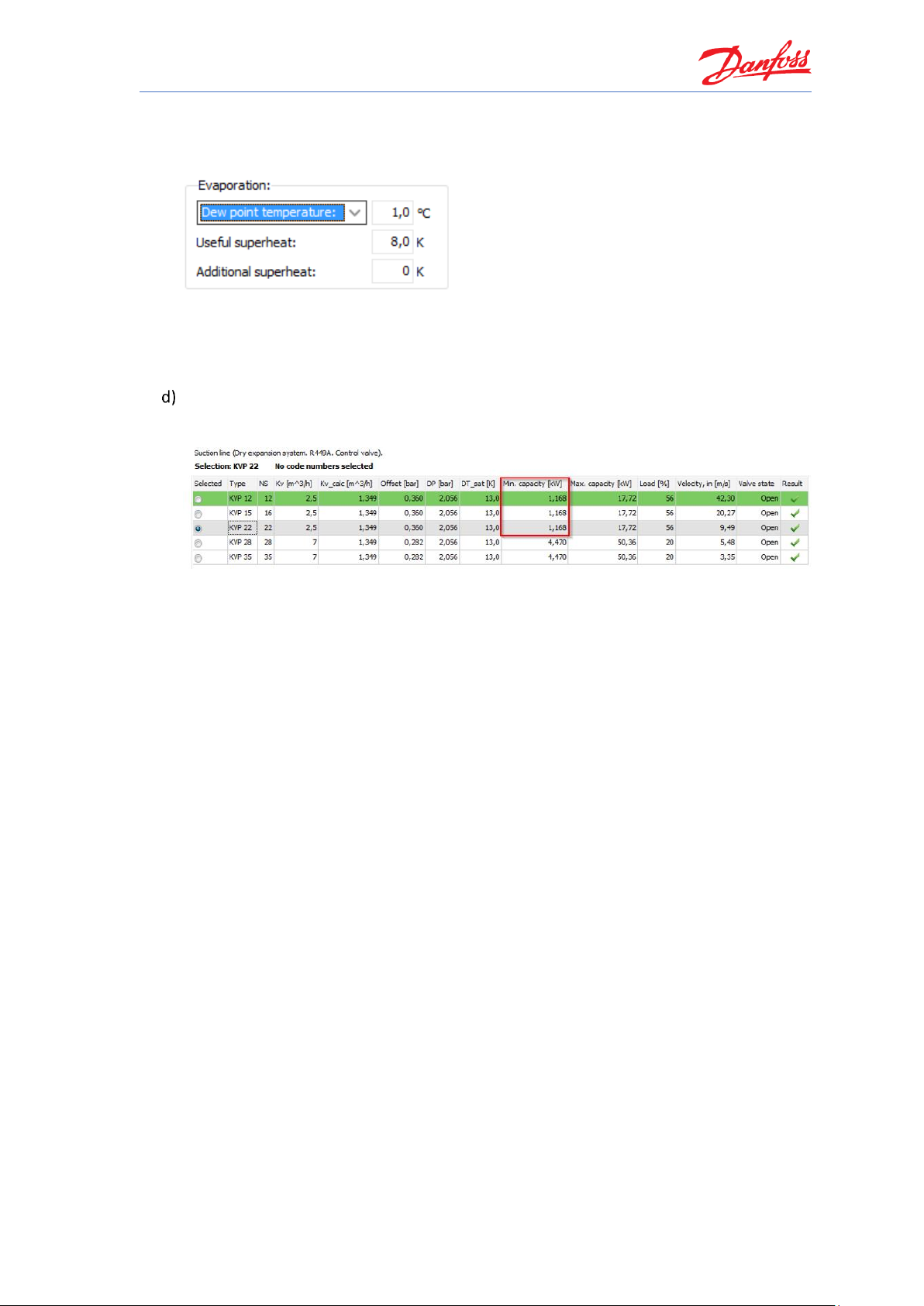
Coolselector®2 Exercises
87
Calculate 5.64 bar – 0.36 bar (offset) = 5.28 bar. Change the evaporation pressure to 5.28
bar and switch afterwards to check the resulting temperature:
At 1 °C there is no risk for ice building and thus, we can conclude that one of the smaller
KVP valves can be used for this system design.
The minimum possible part load, at which the valve is still in stable operation, is about
1.168 kW. Whereas the minimum evaporator capacity is 2 kW. The valve is also suitable
for part load.
Page 94

Page 95

Coolselector®2 Exercises
89
Calculating heat load and selecting components for a cold room
Using Coolselector®2, please calculate a cold room for vegetables storage. The cold room is
located inside a building, but the back of the room is affected by ambient conditions.
Please use the following information to calculate the cold room:
Dimension of the room will be:
• Length: 10 m
• Width: 5 m
• Height: 4 m
Insulation:
• Polyurethane, 100 mm
Floor:
• Not insulated. Made of concrete to withstand fork-lift trucks.
Ambient conditions:
• Ambient condition: 32 °C, 45% RH
• Inside the building: 23 °C, 55% RH
• Below floor: 12 °C
Goods stored:
• Type: Fresh vegetables
• Usage: Medium time (several weeks)
• Stored mass: Unclear, but room volume will be used as much as possible. To
pick up goods, only a small space to walk through is needed.
Refrigeration system:
• Refrigerant: R448A
• A condensing unit can be installed outside behind the room.
• An electronic controller shall be used.
Page 96

Coolselector®2 Exercises
90
Calculating heat load and selecting components for a cold room
Vegetable storage requires that you pay close attention to the storage conditions.
Therefore, please consider the following before starting the cold room calculation in
Coolselector®2:
• Room temperature shall be close to the freezing point to keep respiration
activity low.
• Humidity shall be as high as possible, preferably 95% or even 98% RH
• No goods will be affected by the direct air flow; this keeps a micro climate
around the goods.
• Do not store goods all the way up to the ceiling and keep a good distance to
the walls and between the boxes.
Next, in Coolselector®2, go to ‘Commercial Applications’ and start a cold room calculation:
Starting a cold room calculation opens up a dialog box, which allows you to use a wizard, which
not only guides you through but also helps with educated estimations of all room parameters. If
you are already aware of all relevant values, you can also choose the ‘Manually define room
loads….’ option within Coolselector®2:
Page 97

Coolselector®2 Exercises
91
The help function in the bottom left corner provides further information about the methods and
processes used in the cold room calculations:
Since in this example some essential parameters like “mass of goods” is not known, it is
recommended to use the wizard for this assignment:
Wizard - Step 1 of 3: Dimensions and surroundings
Enter the known dimensions and surrounding conditions. Since the maximum load will be
calculated, the maximum surrounding values should be entered:
Tip: Do not use values that may occur rarely and only for a short time
Page 98

Coolselector®2 Exercises
92
Wizard - Step 2 of 3: Goods
First of all, we know from the assignment that the goods to be stored are “vegetables”, so
choose this in the first drop-down list.
In the assignment, only a little information is given about the usage of the storage. A calculation
based on storable mass per m³ will help: Click on “Estimate mass from room volume…”.
To baseline the estimation, the percentage of room effectively used for placing goods can be
entered. Remember, air needs to flow around the goods and a person also needs to be able to
walk between the racks to pick up goods.
The longer the time goods are stored for, the less space is needed for walking through the room.
The goods can just be stacked up if the storing time is long:
Our case is somewhere in between short-term and long-term storage. The standard value of
50% for vegetables seems to be a little bit too low. Thus, we will increase it to 55%.
Since the goods will be stored on average for ‘some weeks’, the exchange rate per day will be
much lower than 20%. Thus, we will reduce it to 2%:
If you now click “OK”, Coolselector®2 will do the necessary calculations and update the values
for “Total mass in room” and the “Quantity per day”.
Page 99

Coolselector®2 Exercises
93
By default, the inlet temperature is set to 5 K above the recommended storage temperature (see
Step 3 of 3). The goods are assumed to have been pre-cooled. In case the vegetables are stored
directly after harvesting, the inlet temperature would naturally be higher.
In our case, we assume the goods are pre-cooled, and we keep the standard inlet temperature
as it is and click on “Next”:
Wizard - Step 3 of 3: Review recommended values
In most cases, vegetables are stored differently in the cold room compared to on, for example, a
sales shelf and often the humidity has to remain high.
To reach a high humidity level within the cold room, the dehumidification needs to be kept low.
Two parameters are available for adjustment to achieve this, namely:
• Temperature difference between evaporator and room temperature.
• Working time (on-time) of the refrigeration system.
Based on these parameters, the operating hours are estimated/recommended. If you want the
humidity to be higher than the default value of 95%, enter a new value like 98% and click
“Estimate the operating hours”. Coolselector®2 will now change the operating hours and it is
evident that the refrigeration system should only run for 11 hrs (estimated) to achieve the
higher value:
Page 100
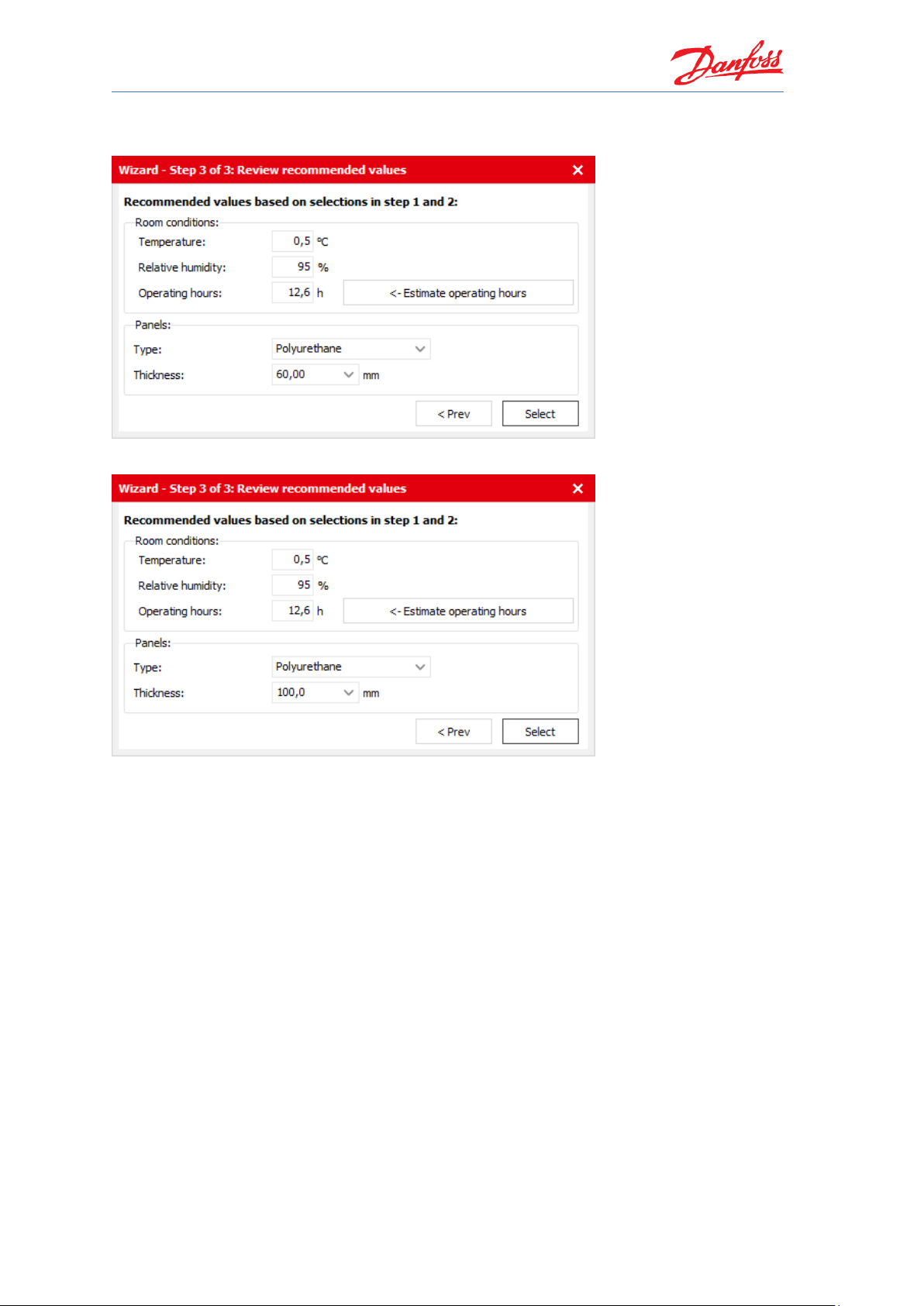
Coolselector®2 Exercises
94
However, in our case, 95% RH will suffice. Thus, change the value back to 95% RH and click on
“Estimate operating hours…” again:
Set the insulation panels to Polyurethane and 100 mm thickness and click “select”:
 Loading...