

Page 1
Installation Guide
Danfoss
148H145_02-201
148H146_02-2018
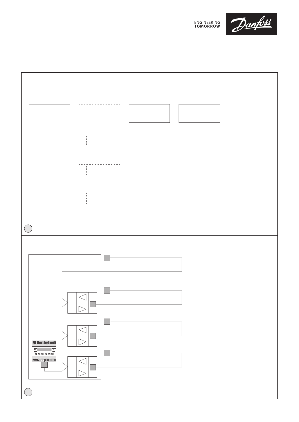
Controller unit and
expansion module
148R9637
Controller
unit
8
1
Expansion
module
GD unit
GD unit
148R9637
GD unit GD unit
Up to 7 expansion modules per controller.
In total up to 96 sensors connected via Field bus
per controller - regardless of number of expansion
modules.
Controller unit
R
Segment 1
R = Resistor 560 Ohm
24 V DC for each address is needed
max. cable length: 900 m
R
Segment 2
R
max. cable length: 900 m
Expansion
module
R
Segment 3
max. cable length: 900 m
R
R
Segment 4
R
R
max. cable length: 900 m
Danfoss
2
© Danfoss | Climate Solutions | 2022.03
AN272543970480en-000201 | 1
Page 2
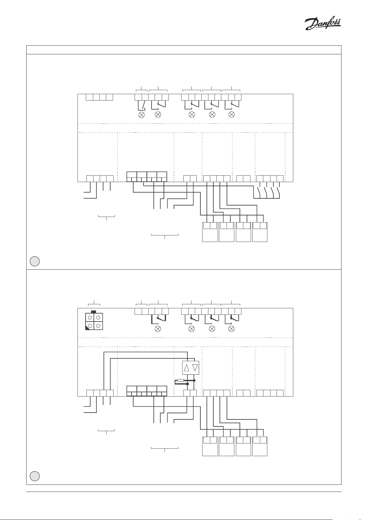
Rela y
Service
24
AP 05 AP 06 AP 07 AP 08
Rela y
Rela y
Rela y
148H138_01-2018
Rela y
24
AP 01 AP 02 AP 03 AP 04
Rela y
Rela y
Rela y
148H144_02-2018
Rela y
Wiring configuration
X_Bus
X_Bus
AR 01
Fault
X2X1 X2
3152
0 VDC
Relay
28
511
39
612
D1 D2 D3 D4
D RF
AR 02
7
Digital output
AR 03
13410
AR 04
14
15
Danfoss
Controller unit
Power/
Main Bus
+-
Main Bus_A
Main Bus_B
4
3
1
2
X10
VDC
0 VDC
Main Bus_A
Main Bus_B
A
Output Main bus for PLC/PC etc.
Power Analog
< 24 VDC
1 2 3 4
X11
<
24 VDC
0 VDC
24 VDC
Output Field bus
0 VDC
0 VDC
Field Bus_A
B
Field Bus
Field Bus_A
1
X12
Field Bus_B
Field Bus_B
2
3
AI_01
4-20 mA
Analog
input
AI_02
46
24 VDC
output
AI_03
AI_04
AO_01
AO_02
578910 11 12
24 VDC
4-20 mA
24 VDC
4-20 mA
4-20 mA
Digital
input
DI_01
24 VDC
DI_02
DI_03
DI_04
3
VDC
0 VDC
Power/
X10
tool
Main Bus
+
1
-
Field Bus_A
3
2
Field Bus_A
B
Field bus
AR 05
X2X1 X2
28
511
39
612
AR 06
7
D1 D2 D3 D4
Digital output
AR 07
13410
AR 08
14
15
Danfoss
Expansion Module
Field Bus_B
4
Field Bus_B
Field Bus
0 VDC
< 24 VDC
1 2 3 4
X11
Power
24 VDC
0 VDC
<
0 VDC
24 VDC
C
Field bus
Analog
input
Analog
output
560 R
AI_01
AI_02
AI_03
AI_04
AO_03
AO_04
1
2
X12
Field Bus_A
Field Bus_B
46
3
24 VDC
4-20 mA
578910 11 12
24 VDC
24 VDC
4-20 mA
24 VDC
4-20 mA
4-20 mA
4
© Danfoss | Climate Solutions | 2022.03
AN272543970480en-000201 | 2
Page 3

ENGLISH
Application Intended for Use
The Danfoss gas detection controller unit is controlling one or
multiple gas detectors, for monitoring, detection and warning
of toxic and combustible gases and vapours in the ambient air.
The controller unit meets the requirements according to EN 378,
VBG 20 and the guidelines "Safety requirements for ammonia
(NH₃) refrigeration systems". The controller can also be used for
monitoring other gases and measuring values.
The intended sites are all areas being directly connected to
the public low voltage supply, e.g. residential, commercial and
industrial ranges as well as small enterprises (according to EN 5502).
The controller unit may only be used in ambient conditions as
specified in the technical data.
The controller unit must not be used in potentially explosive
atmospheres.
Description
The controller unit is a warning and control unit for the continuous
monitoring of different toxic or combustible gases and vapours
as well as of Freon refrigerants. The controller unit is suitable for
the connection of up to 96 digital sensors via the 2-wire bus. Up
to 32 analog inputs for the connection of sensors with 4 – 20 mA
signal interface are available in addition. The controller unit can be
employed as pure analog controller, as analog/digital or as digital
controller. The total number of connected sensors, however, may
not exceed 128 sensors.
Up to four programmable alarm thresholds are available for each
sensor. For binary transmission of the alarms there are up to 32
relays with potential-free change-over contact and up to 96 signal
relays.
Comfortable and easy operation of the controller unit is done via
the logical menu structure. A number of integrated parameters
enables the realisation of various requirements in the gas
measuring technique. Configuration is menu-driven via the
keypad. For fast and easy configuration, you can use the PC Tool.
Prior to commissioning please consider the guidelines for wiring
and commissioning of the hardware.
Normal Mode:
In normal mode, the gas concentrations of the active sensors are
continuously polled and displayed at the LC display in a scrolling
way. In addition, the controller unit continuously monitors itself, its
outputs and the communication to all active sensors and modules.
Alarm Mode:
If the gas concentration reaches or exceeds the programmed
alarm threshold, the alarm is started, the assigned alarm relay is
activated and the alarm LED (light red for alarm 1, dark red for
alarm 2 + n) starts to flash. The set alarm can be read from the
menu Alarm Status.
When the gas concentration falls below the alarm threshold and
the set hysteresis, the alarm is automatically reset. In latching
mode, the alarm must be reset manually directly at the alarm
triggering device after falling below the threshold. This function
is obligatory for combustible gases detected by catalytic bead
sensors generating a falling signal at too high gas concentrations.
Special Status Mode:
In the special status mode there are delayed measurements for the
operation side, but no alarm evaluation.
The special status is indicated on the display and it always
activates the fault relay.
The controller unit adopts the special status when:
- faults of one or more active devices occur,
- the operation starts up after return of voltage (power on),
- the service mode is activated by the user,
- the user reads or changes parameters,
- an alarm or signal relay is manually overridden in the alarm
status menu or via digital inputs.
Fault Mode:
If the controller unit detects an incorrect communication of an
active sensor or module, or if an analog signal is outside the
admissible range (< 3.0 mA > 21.2 mA), or if there are internal
function errors coming from the self-control modules incl.
watchdog and voltage control, the assigned fault relay is set and
the error LED starts to flash. The error is displayed in the menu
Error Status in clear text. After removal of the cause, the error
message must be acknowledged manually in the menu Error
Status.
Restart Mode (Warm-up Operation):
Gas detection sensors need a running-in period, until the chemical
process of the sensor reaches stable conditions. During this
running-in period the sensor signal can lead to an unwanted
release of a pseudo alarm.
Depending on the connected sensor types, the longest warm-up
time must be entered as power-on time in the controller. This
power-on time is started at the controller unit after switching on
the power supply and/or after the return of voltage. While this
time is running out, the gas controller unit does not display any
values and does not activate any alarms; the controller system is
not yet ready for use.
The power-on status occurs on the first line of the starting menu.
Service Mode:
This operation mode includes commissioning, calibration, testing,
repair and decommissioning.
The service mode can be enabled for a single sensor, for a group
of sensors as well as for the complete system. In active service
mode pending alarms for the concerned devices are held, but new
alarms are suppressed.
UPS Functionality (option - not all controllers include a UPS):
The supply voltage is monitored in all modes. When reaching
the battery voltage in the power pack, the UPS function of the
controller unit is enabled and the connected battery is charged.
If the power fails, the battery voltage drops down and generates
the power failure message.
At empty battery voltage, the battery is separated from the circuit
(function of deep discharge protection). When the power is
restored, there will be an automatic return to the charging mode.
No settings and therefore no parameters are required for the UPS
functionality.
In order to access the user manual and menu overview, please go
to further documentation.
© Danfoss | Climate Solutions | 2022.03
Further documentation:
AN272543970480en-000201 | 3
Page 4

© Danfoss | Climate Solutions | 2022.03
AN272543970480en-000201 | 4
 Loading...