

Page 1
User Manual
PLUS+1® GUIDE Software
PLUS+1 Function Block Library—Control
Function Blocks
www.danfoss.com
Page 2

User Manual
PLUS+1® Compliant Function Block Library—Control Function Blocks
Revision history Table of revisions
Date Changed Rev
January 2019 Rebranding 0101
May 2016 Updates for new library version. CA
April 2014 Supports Rev 3.00 BC
2 | © Danfoss | January 2019 11062085 | AQ284462219091en-000101
Page 3

User Manual
PLUS+1® Compliant Function Block Library—Control Function Blocks
Contents
Risk Reduction
Design, Test, and Secure to Reduce Risks................................................................................................................................6
Design...................................................................................................................................................................................................6
Test.........................................................................................................................................................................................................6
Secure................................................................................................................................................................................................... 7
Controller_PI Function Block
Inputs....................................................................................................................................................................................................8
Outputs................................................................................................................................................................................................ 9
Function Block Connections...................................................................................................................................................... 11
Status Logic......................................................................................................................................................................................12
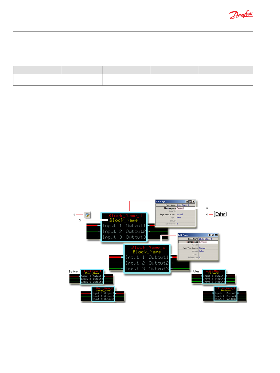
Identical Function Blocks Need Different Namespace Values to Successfully Compile...................................... 12
Change Namespace Value.....................................................................................................................................................12
IEC 61508-3 Annex D Supplemental Information.............................................................................................................. 14
Controller_PID Function Block
Inputs..................................................................................................................................................................................................15
Outputs..............................................................................................................................................................................................16
Function Block Connections...................................................................................................................................................... 18
Status Logic......................................................................................................................................................................................19
Identical Function Blocks Need Different Namespace Values to Successfully Compile...................................... 19
Change Namespace Value.....................................................................................................................................................19
IEC 61508-3 Annex D Supplemental Information.............................................................................................................. 21
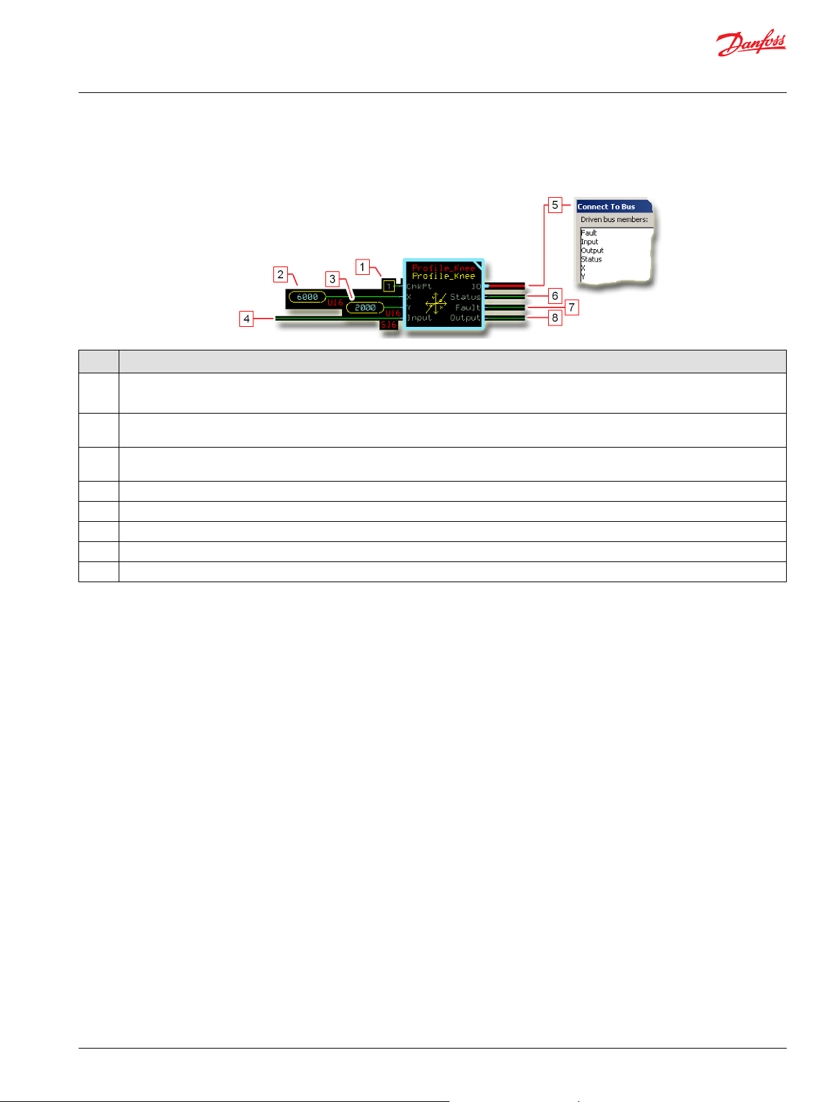
Profile_Knee Function Block
Inputs..................................................................................................................................................................................................22
Outputs..............................................................................................................................................................................................22
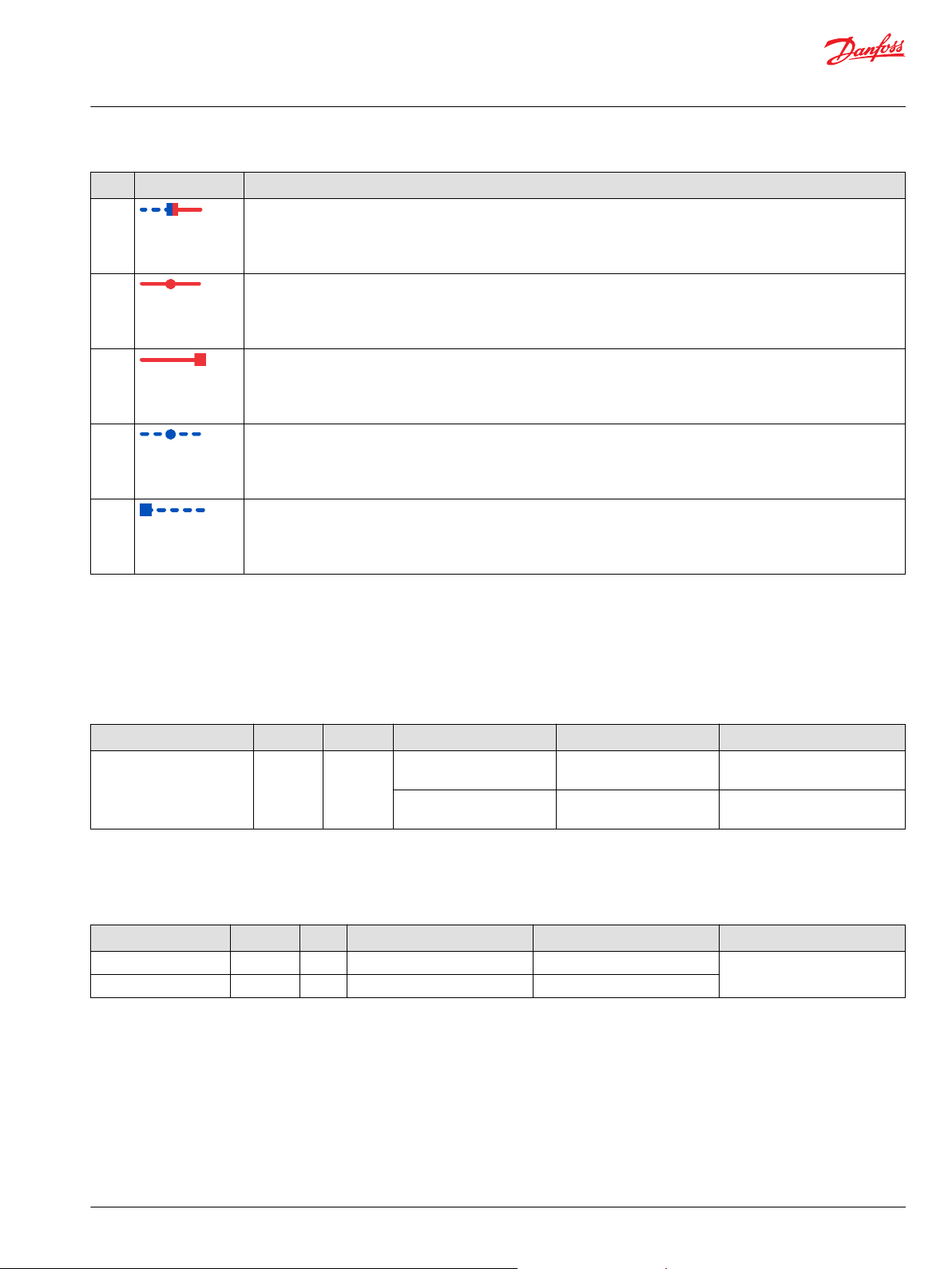
Function Block Connections...................................................................................................................................................... 23
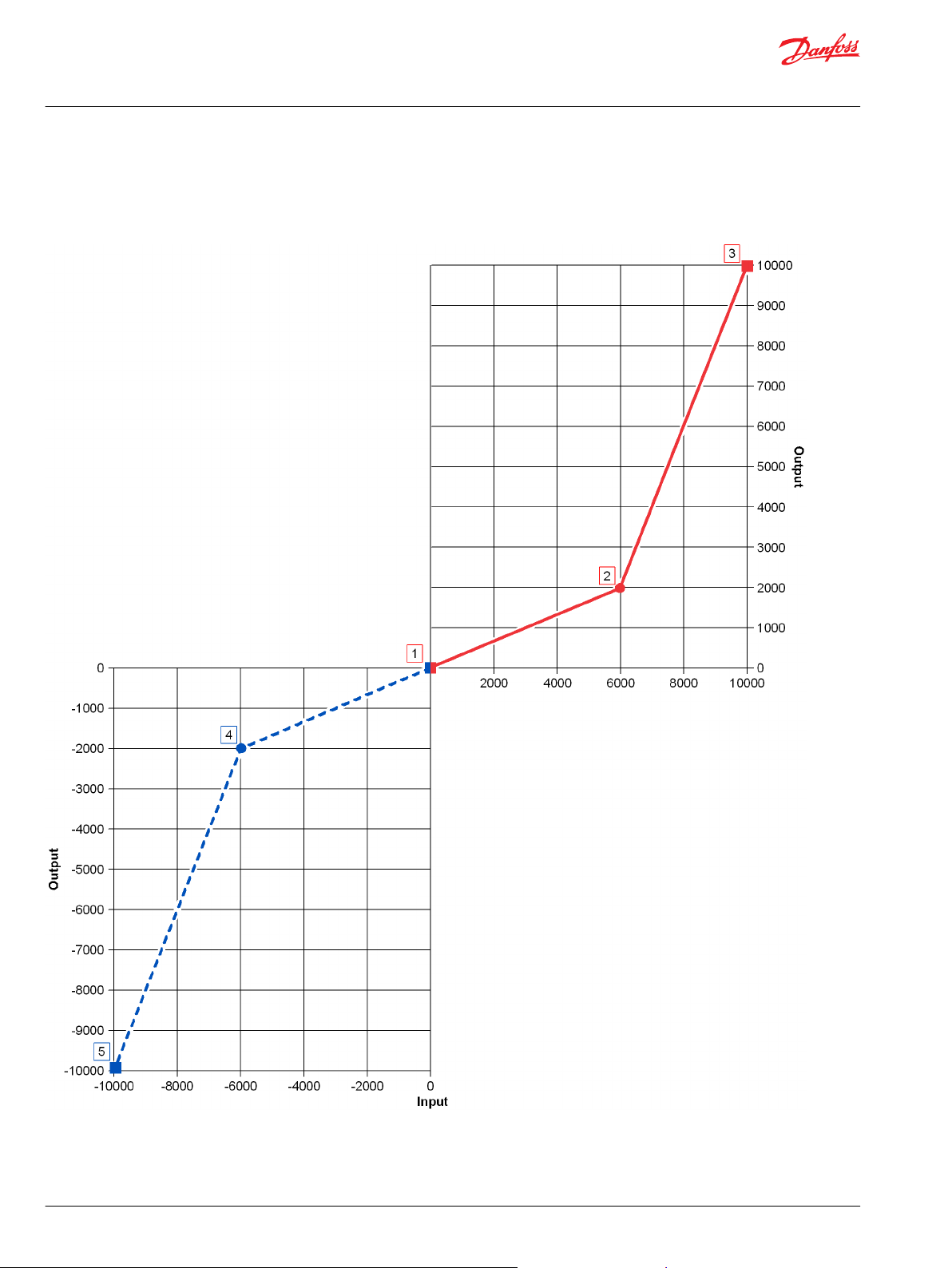
Function Block Example.............................................................................................................................................................. 24
Status and Fault Logic..................................................................................................................................................................25
Status Logic.................................................................................................................................................................................25
Fault Logic...................................................................................................................................................................................25
Identical Function Blocks Need Different Namespace Values to Successfully Compile...................................... 25
Change Namespace Value.....................................................................................................................................................26
IEC 61508-3 Annex D Supplemental Information.............................................................................................................. 27
Profile_6Pt Function Block
Inputs..................................................................................................................................................................................................28
Outputs..............................................................................................................................................................................................29
Function Block Connections...................................................................................................................................................... 29
Function Block Example.............................................................................................................................................................. 30
Status Logic......................................................................................................................................................................................31
Identical Function Blocks Need Different Namespace Values to Successfully Compile...................................... 31
Change Namespace Value.....................................................................................................................................................32
IEC 61508-3 Annex D Supplemental Information.............................................................................................................. 33
Profile_8Pt Function Block
Inputs..................................................................................................................................................................................................34
Outputs..............................................................................................................................................................................................35
Function Block Connections...................................................................................................................................................... 35
Function Block Example.............................................................................................................................................................. 37
Status and Fault Logic..................................................................................................................................................................39
Status Logic.................................................................................................................................................................................39
Fault Logic...................................................................................................................................................................................39
Identical Function Blocks Need Different Namespace Values to Successfully Compile...................................... 39
Change Namespace Value.....................................................................................................................................................40
IEC 61508-3 Annex D Supplemental Information.............................................................................................................. 41
Comparison of 6Pt, 8Pt, and Profile_Knee Function Blocks
Ackermann Function Block
Inputs..................................................................................................................................................................................................43
©
Danfoss | January 2019 11062085 | AQ284462219091en-000101 | 3
Page 4

User Manual
PLUS+1® Compliant Function Block Library—Control Function Blocks
Contents
Outputs..............................................................................................................................................................................................44
Function Block Connections...................................................................................................................................................... 45
Status and Fault Logic..................................................................................................................................................................46
Status Logic.................................................................................................................................................................................46
Fault Logic...................................................................................................................................................................................46
Steering Modes...............................................................................................................................................................................47
Identical Function Blocks Need Different Namespace Values to Successfully Compile...................................... 48
Change Namespace Value.....................................................................................................................................................49
IEC 61508-3 Annex D Supplemental Information.............................................................................................................. 50
Ackermann_Spd Function Block
Inputs..................................................................................................................................................................................................51
Outputs..............................................................................................................................................................................................52
Function Block Connections...................................................................................................................................................... 53
Status and Fault Logic..................................................................................................................................................................54
Status Logic.................................................................................................................................................................................54
Fault Logic...................................................................................................................................................................................54
Steering Modes...............................................................................................................................................................................55
Identical Function Blocks Need Different Namespace Values to Successfully Compile...................................... 56
Change Namespace Value.....................................................................................................................................................57
IEC 61508-3 Annex D Supplemental Information.............................................................................................................. 58
Ackermann_Strg Function Block
Inputs..................................................................................................................................................................................................59
Outputs..............................................................................................................................................................................................60
Function Block Connections...................................................................................................................................................... 61
Status and Fault Logic..................................................................................................................................................................62
Status Logic.................................................................................................................................................................................62
Fault Logic...................................................................................................................................................................................62
Steering Modes...............................................................................................................................................................................63
Identical Function Blocks Need Different Namespace Values to Successfully Compile...................................... 64
Change Namespace Value.....................................................................................................................................................65
IEC 61508-3 Annex D Supplemental Information.............................................................................................................. 66
Inverse_Acker Function Block
Inputs..................................................................................................................................................................................................67
Outputs..............................................................................................................................................................................................68
Function Block Connections...................................................................................................................................................... 69
How the Inverse_Acker Function Block Works to Restore Lost Ang Inputs..............................................................70
Status and Fault Logic..................................................................................................................................................................71
Status Logic.................................................................................................................................................................................71
Fault Logic...................................................................................................................................................................................71
Steering Modes...............................................................................................................................................................................71
Identical Function Blocks Need Different Namespace Values to Successfully Compile...................................... 73
Change Namespace Value.....................................................................................................................................................74
IEC 61508-3 Annex D Supplemental Information.............................................................................................................. 75
Hysteresis Function Block
Inputs..................................................................................................................................................................................................76
Outputs..............................................................................................................................................................................................76
Function Block Connections...................................................................................................................................................... 77
Function Block Example.............................................................................................................................................................. 78
Status and Fault Logic..................................................................................................................................................................80
Status Logic.................................................................................................................................................................................80
Fault Logic...................................................................................................................................................................................80
Identical Function Blocks Need Different Namespace Values to Successfully Compile...................................... 80
Change Namespace Value.....................................................................................................................................................81
IEC 61508-3 Annex D Supplemental Information.............................................................................................................. 82
State_Brake Function Block
Inputs..................................................................................................................................................................................................83
4 | © Danfoss | January 2019 11062085 | AQ284462219091en-000101
Page 5

User Manual
PLUS+1® Compliant Function Block Library—Control Function Blocks
Contents
Outputs..............................................................................................................................................................................................83
Parameters........................................................................................................................................................................................84
About the Para Input...............................................................................................................................................................86
Function Block Connections...................................................................................................................................................... 86
Function Block Examples............................................................................................................................................................ 87
Status and Fault Logic..................................................................................................................................................................91
Status Logic.................................................................................................................................................................................92
Fault Logic...................................................................................................................................................................................92
Identical Function Blocks Need Different Namespace Values to Successfully Compile...................................... 92
Change Namespace Value.....................................................................................................................................................93
IEC 61508-3 Annex D Supplemental Information.............................................................................................................. 94
©
Danfoss | January 2019 11062085 | AQ284462219091en-000101 | 5
Page 6

User Manual
PLUS+1® Compliant Function Block Library—Control Function Blocks
Risk Reduction
Design, test, and secure applications that you develop to reduce risks of personal injury and equipment
damage.
Design, Test, and Secure to Reduce Risks
Applications created with PLUS+1® GUIDE typically control equipment such as tractors, cranes, and
harvesters.
Using heavy, powerful, and mobile off-road equipment always involves the risk of personal injury and
equipment damage, even when this equipment is operating under normal operating conditions.
Abnormal operating conditions greatly increase the risk of personal injury and equipment damage.
The PLUS+1® program has no automatic protections against these risks. The tool has no protection
against the risks that result from bugs in the tool software, errors in the tool manual, or incompatibilities
between software versions of the tool.
You must:
•
Design your application to reduce these risks.
•
Test your application to reduce these risks.
•
Secure your application against unauthorized changes in its operating parameters to reduce these
risks.
Design
Test
As you design your application, you must include the fault checking and the error handling needed to
reduce risks in normal and abnormal operating conditions.
Consider the following when developing fault checking and error handling for your PLUS+1® GUIDE
application:
•
How the machine is normally used.
•
Possible operator errors and their consequences.
•
Industry safety standards and legal requirements.
•
Input and output failures and their consequences. These failures can include:
Joystick, sensor, and other inputs suddenly going to ±100 % or to 0 %.
‒
Joystick, sensor, and other inputs suddenly going to ±100 % or to 0 %.
‒
Outputs that control machinery direction, speed, and force suddenly changing direction or going
‒
to ±100 % or to 0 %.
Decide how likely each failure is. The more likely a failure, the more you need to protect against
the consequences of the failure.
•
The sequence of events and consequences of a fault or error.
•
The sequence of events and consequences of an emergency stop.
After creating an application, you are responsible for testing the application.
Download your application to hardware and test its operation under both normal and abnormal
operating conditions. Make sure:
•
Individual inputs produce expected outputs.
•
Fault handling and error checking work as designed.
You must repeat your tests when you make configuration, calibration, or software changes to the
application.
6 | © Danfoss | January 2019 11062085 | AQ284462219091en-000101
Page 7

User Manual
PLUS+1® Compliant Function Block Library—Control Function Blocks
Risk Reduction
Secure
You have the responsibility to secure your application against unauthorized changes.
Always use the PLUS+1® GUIDE program’s Toolkey feature to restrict access to your application’s
operating parameters.
•
Without Toolkey protection, there is an increased risk that unauthorized personnel could use the
PLUS+1® Service Tool program to change your application’s operating parameters.
Changes in your application’s operating parameters might cause unexpected machinery movement
that results in personal injury and equipment damage.
•
Toolkey protection reduces the risk that unauthorized personnel could use the PLUS+1® program to
change your application’s operating parameters.
Refer to How to Use the Toolkey to Restrict Service Tool Access to Application Values in the PLUS+1—How-to
chapter of the PLUS+1 GUIDE User Manual (Danfoss part 10100824).
©
Danfoss | January 2019 11062085 | AQ284462219091en-000101 | 7
Page 8
User Manual
PLUS+1® Compliant Function Block Library—Control Function Blocks
Controller_PI Function Block
Use the Controller_PI (Proportional and Integral) function block to control a closed-loop application.
This function block achieves closed-loop control by changing its output signal to get its feedback signal
to equal its set point signal.
You can use this function block in:
•
Constant speed control applications.
•
Propel functions such as cruise control or straight tracking.
•
Work functions such as transit mixers.
The Controller_PID function block is available to implement closed-loop control through proportional,
integral and derivative (PID) functions. See Controller_PID Function Block. The Controller_PI function
block uses less memory than the Controller_PID function block.
Inputs
The inputs to the Controller_PI function block are described.
Use only the data types specified in this table. Other data types cause compiler errors.
Item Type Range Description
ChkPt BOOL ——
P Gain S16 -32768–32767 The proportional gain (P Gain) factor that determines how much the difference between Stpt and
I Gain S16 -32768–32767 The integral gain (I Gain) factor that determines how much the continual summing of the difference
Rst/Hld U8 0–3 The reset/hold (Rst/Hld) setting:
True—include the function block’s built-in Advanced Checkpoint with Namespace in the compiled
•
LHX download file.
False—exclude the function block’s built-in Advanced Checkpoint with Namespace components
•
from the compiled LHX download file.
Fdbk influences the Output.
1000 = 1 (unity gain)
between Stpt and Fdbk influences the Output. Integration occurs on every process loop. I Gain
multiplies by OS.ExecTm to take account for processing time differences.
10000 = 1 (unity gain)
0 = Normal operation—no reset or hold.
•
1 = Hold the integrator to the current values.
•
2 = Reset the integrator to the Rst Val.
•
3 = Reset the entire Output.
•
8 | © Danfoss | January 2019 11062085 | AQ284462219091en-000101
Page 9
User Manual
PLUS+1® Compliant Function Block Library—Control Function Blocks
Controller_PI Function Block
Item Type Range Description
Rst Val S16 -32768–32767 The reset value (Rst Val) set in during a reset operation.
This item has no predefined unit value.
Assign the same unit values to Rst Val, I Stop, Max, Min, Dband, Stpt, Fdbk, Error, P, I, and Output.
I Stop U16 0–65535
Max S16 -32768–32767 The maximum allowed output value.
Min S16 -32768–32767 The minimum allowed output value.
Dband U16 0–65535
Stpt S16 -32768–32767 The system set point (Stpt). The desired system output.
Fdbk S16 -32768–32767 The system feedback (Fdbk). The actual, measured system output.
Sets the value at which the integral pauses where: Absolute (Stpt-Fdbk) > I_Stop.
Use to limit overshoot due to large steps changes in errors. To disable this feature, set I_Stop = 65535.
This item has no predefined unit value.
Assign the same unit values to Rst Val, I Stop, Max, Min, Dband, Stpt, Fdbk, Error, P, I, and Output.
When (P + IMax, the integrator holds and can only be reduced.) >
This item has no predefined unit value.
Assign the same unit values to Rst Val, I Stop, Max, Min, Dband, Stpt, Fdbk, Error, P, I, and Output.
When (P) + I) < Min, the integrator holds and can only be increased.
This item has no predefined unit value.
Assign the same unit values to Rst Val, I Stop, Max, Min, Dband, Stpt, Fdbk, Error, P, I, and Output.
The allowed difference between Stpt and Fdbk before the function block begins error correction. The
function block makes no corrections until the error becomes greater than this value. The error used in
PID error calculation stays at zero until it becomes greater than the Dband value.
This item has no predefined unit value.
Assign the same unit values to Rst Val, I Stop, Max, Min, Dband, Stpt, Fdbk, Error, P, I, and Output.
This item has no predefined unit value.
Assign the same unit values to Rst Val, I Stop, Max, Min, Dband, Stpt, Fdbk, Error, P, I, and Output.
This item has no predefined unit value.
Assign the same unit values to Rst Val, I Stop, Max, Min, Dband, Stpt, Fdbk, Error, P, I, and Output.
Outputs
The outputs of the Controller_PI function block are described.
Item Type Range Description
IO Bus —— Outputs a bus with all of the function block's input and output signals.
The bus conveniently distributes this function block's signals to your application.
Status U16 —— Reports the status of the function block.
This output follows the standard bitwise scheme described in the Status topic.
Fault U16 —— Reports the faults of the function block.
This output follows the standard bitwise scheme described in the Fault topic.
Error S32 -65535–65535
Saturate
P S16 -32768–32767 The proportional calculation’s contribution to the Output.
U8
0–2
The error or difference between the Stpt and the Fdbk.
This item has no predefined unit value.
Assign the same unit values to Rst Val, I Stop, Max, Min, Dband, Stpt, Fdbk, Error, P, I, and Output.
Output saturation indicator:
0 = No saturation.
•
1 = Down saturation. The function block’s Output value equals its Min value.
•
2 = Up saturation. The function block’s Output value equals its Max value.
•
P = (Stpt – Fdbk) * P Gain) / 1000
This item has no predefined unit value.
Assign the same unit values to Rst Val, I Stop, Max, Min, Dband, Stpt, Fdbk, Error, P, I, and Output.
©
Danfoss | January 2019 11062085 | AQ284462219091en-000101 | 9
Page 10

User Manual
PLUS+1® Compliant Function Block Library—Control Function Blocks
Controller_PI Function Block
Item Type Range Description
I S16 -32768–32767 The integral calculation’s contribution to the Output.
I = Σ [(Stpt – Fdbk) * I Gain * OS.ExecTm)/10000]
This item has no predefined unit value.
Assign the same unit values to Rst Val, I Stop, Max, Min, Dband, Stpt, Fdbk, Error, P, I, and Output.
Output S16 -32768–32767 Sum of the internal P and I values.
The sum of P and I may not equal Output because the function block:
Calculates the P and I as S32 data types and then restricts them to the S16 range before returning an
•
output.
Calculates the Output before it restricts the P, I, and D values to the S16 range.
•
Bounds the Output to within a range defined by the Max and Min values.
•
This item has no predefined unit value.
Assign the same unit values to Rst Val, I Stop, Max, Min, Dband, Stpt, Fdbk, Error, P, I, and Output.
10 | © Danfoss | January 2019 11062085 | AQ284462219091en-000101
Page 11
User Manual
PLUS+1® Compliant Function Block Library—Control Function Blocks
Controller_PI Function Block
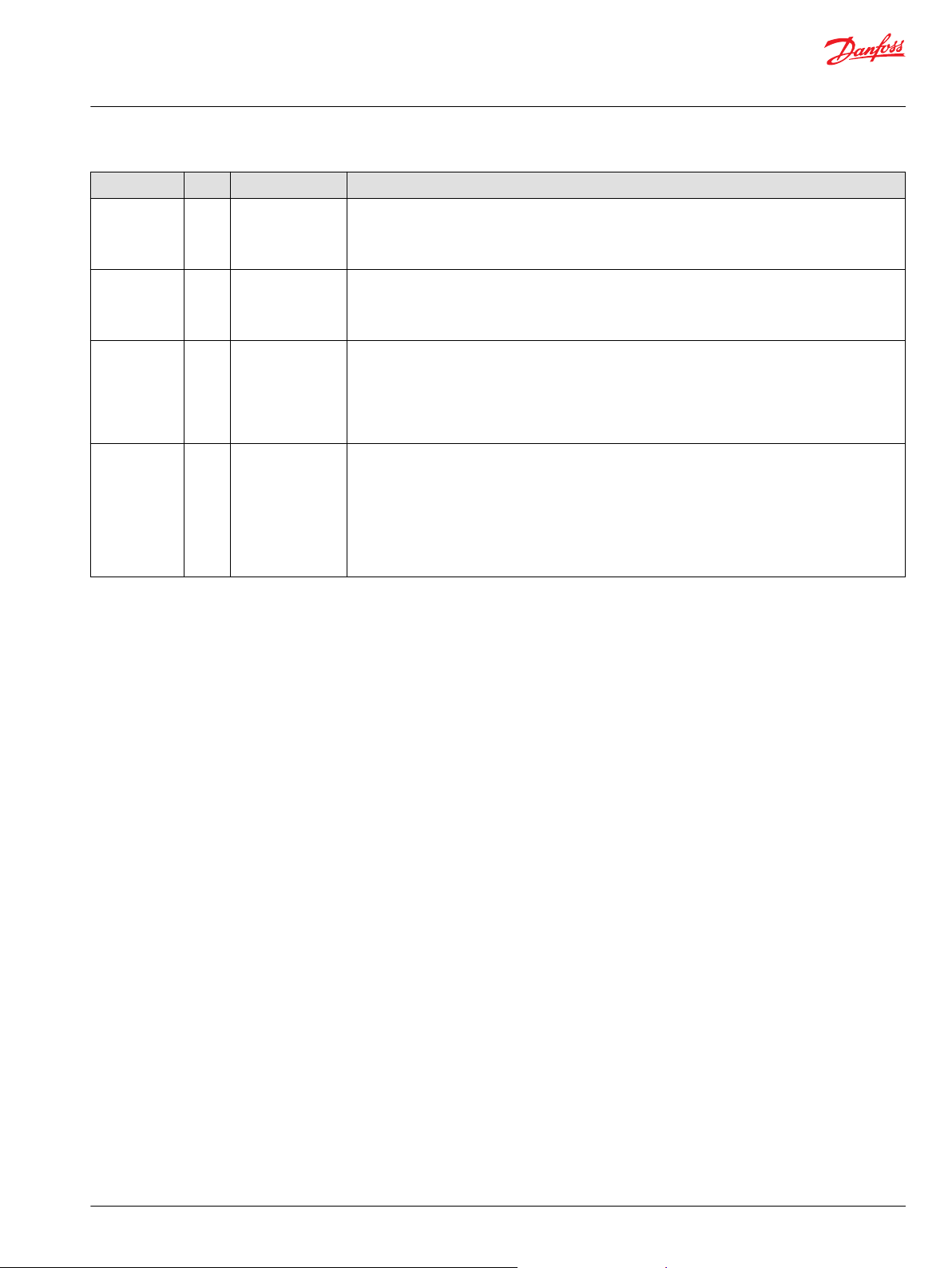
Function Block Connections
Connections you can make with the function block are described.
Description
Item
1.
2. The proportional gain (P Gain) factor that determines how much the Output is influenced by the difference in Stpt and Fdbk.
3. The integral gain (I Gain) factor that determines how much the Output is influenced by continual summing of the difference between Stpt
4. The reset/hold (Rst/Hld) setting:
5.
6. Sets the value at which the integral pauses where: Absolute (Stpt-Fdbk) ≥ I_Stop.
7.
8.
9.
10.
11.
12. Outputs a bus with all of the function block's input and output signals.
13. Reports the status of the function block.
14. The error or difference between the Stpt and the Fdbk.
15. Output saturation indicator:
16.
17.
18.
True—include the function block’s built-in Advanced Checkpoint with Namespace in the compiled LHX download file.
•
False—exclude the function block’s built-in Advanced Checkpoint with Namespace components from the compiled LHX download file.
•
and Fdbk.
0 = Normal operation—no reset or hold.
•
1 = Hold the integrator to the current values.
•
2 = Reset the integrator to the Rst Val.
•
3 = Reset the entire Output.
•
The reset value (Rst Val) set during a reset operation.
The maximum allowed output value.
The minimum allowed output value.
The allowed difference between Stpt and Fdbk before the function block begins error correction.
The system set point (Stpt).
The system feedback (Fdbk).
0 = No saturation.
•
1 = Down saturation. The function block’s Output value equals its Min value.
•
2 = Up saturation. The function block’s Output value equals its Max value.
•
The proportional calculation’s contribution to the Output.
The integral calculation’s contribution to the Output.
Sum of the internal P and I values.
©
Danfoss | January 2019 11062085 | AQ284462219091en-000101 | 11
Page 12
User Manual
PLUS+1® Compliant Function Block Library—Control Function Blocks
Controller_PI Function Block
Status Logic
This topic describes how status logic is indicated for the function block.
Condition Hex
Invalid setup. 0x8008 1000 Rst/Hld value is out of
*
Bit 16 set to 1 identifies a standard Danfoss status or fault code.
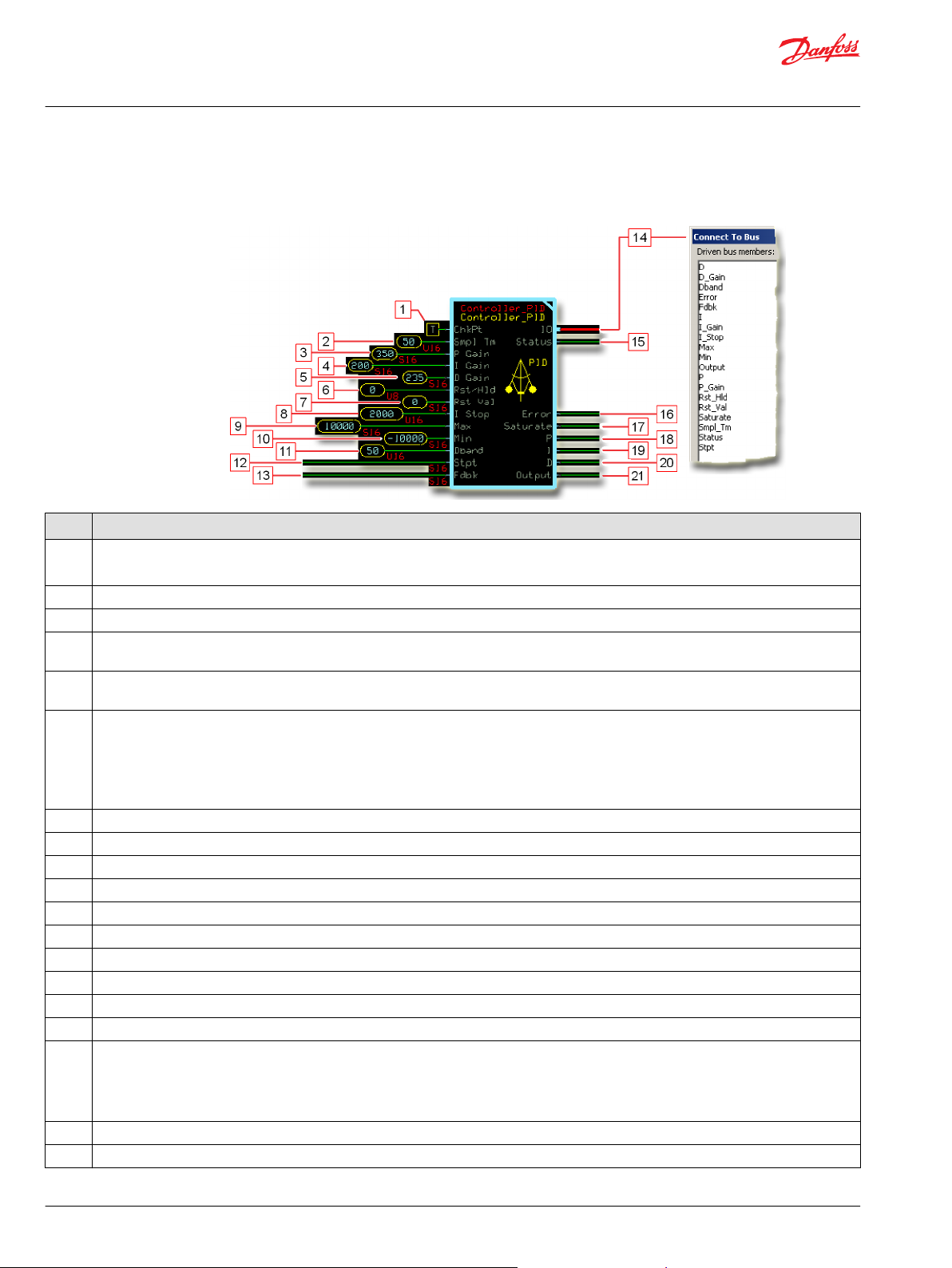
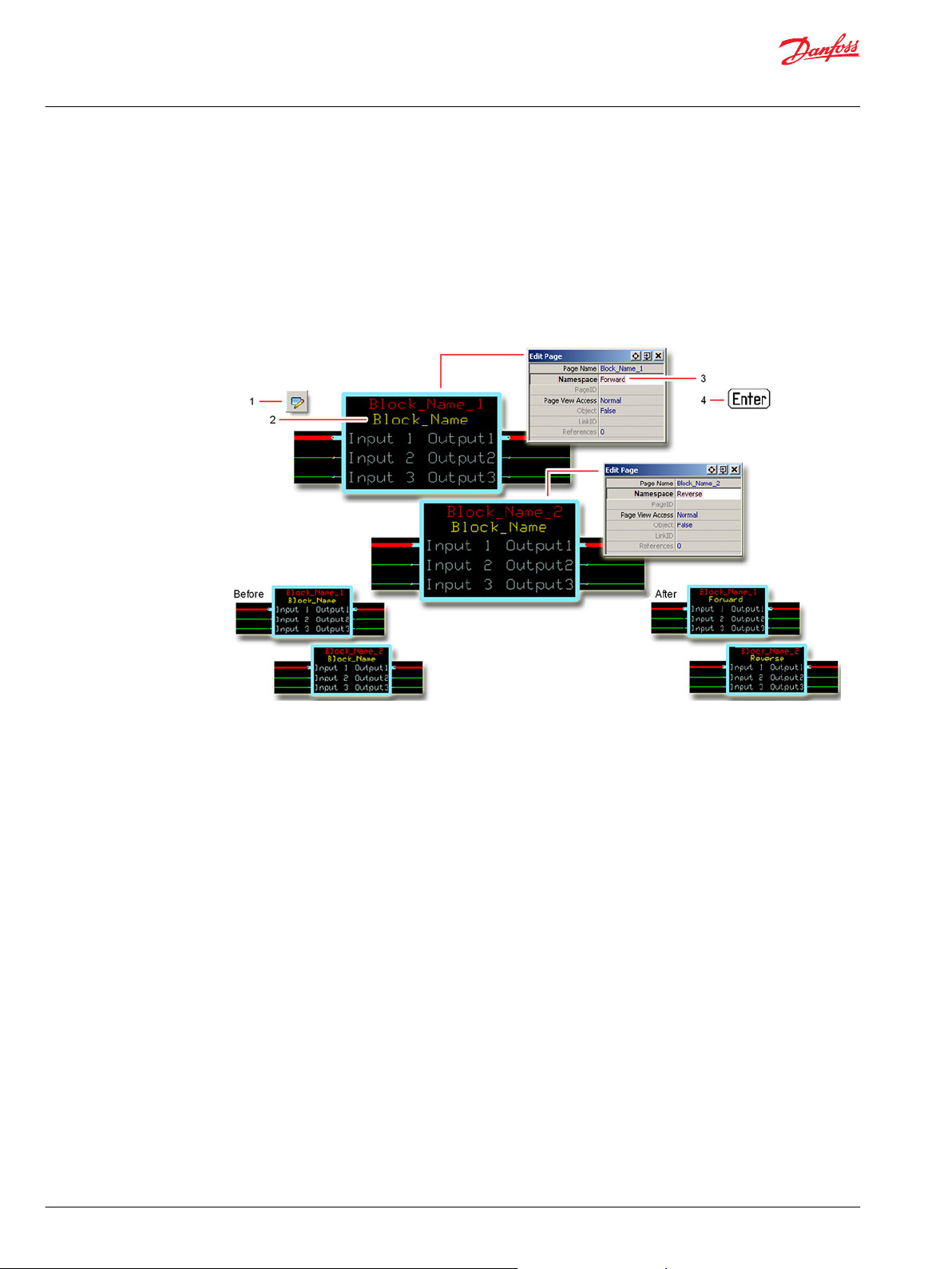
Identical Function Blocks Need Different Namespace Values to Successfully Compile
*
Binary Cause Response Correction
Rst/Hld becomes 0. Return the Rst/Hld value to
range.
If you use the same function block more than once in an application, you must change each function
block’s namespace value to avoid compiler errors.
All function blocks contain Advanced Checkpoint with Namespace components that enable the PLUS+1
Service Tool to read block input and output values.
Some function blocks contain non-volatile memory components that store function block operating
parameters.
Both these components use memory names (“aliases”) to allocate memory. Identical memory names
cause compiler errors.
The namespace value adds a unique prefix to each component name to avoid errors. Keep each
namespace value short to save controller memory.
within its expected range.
®
Change Namespace Value
To successfully compile your application, change the namespace value for function blocks that are used
more than once in an application.
12 | © Danfoss | January 2019 11062085 | AQ284462219091en-000101
Page 13

User Manual
PLUS+1® Compliant Function Block Library—Control Function Blocks
Controller_PI Function Block
1. In the PLUS+1® GUIDE menu bar, click the Query/Change button.
2. Click on the function block whose namespace you want to set to a unique value.
The Edit Page window opens.
3. In the Edit Page window, enter a meaningful Namespace value.
Namespace values are case-sensitive.
•
To save controller memory, use a short namespace value.
•
4. Press Enter.
5. Repeat these steps to enter unique namespace values for other identical function blocks.
©
Danfoss | January 2019 11062085 | AQ284462219091en-000101 | 13
Page 14
User Manual
PLUS+1® Compliant Function Block Library—Control Function Blocks
Controller_PI Function Block
IEC 61508-3 Annex D Supplemental Information
The following table provides IEC 61508-3 Annex D supplemental information.
Item
Function block name Controller_PI
Function block version 4.0.
Function block development
environment
Compatible hardware
Function block developed in
compliance with
Competence required of
function block integrator
Contacting Danfoss
Description
PLUS+1® GUIDE version 8.1 and later.
Verified in the PLUS+1® GUIDE compile process.
When the PLUS+1® GUIDE compiler finds a function block that is incompatible with hardware, it aborts the compile
process and logs an error message. The error message gives the location of the function block and states “Error 80:
component not supported in hwd.”
Danfoss Software Product Development Process (PDP), which includes ISO 9001 and IEC 61508-3 standards.
The knowledge, competence, and training required to:
Understand this manual.
•
Use the PLUS+1® GUIDE program to develop a machine control application.
•
Follow quality software practices to develop a machine control application.
•
https://www.danfoss.com/en/products/software/dps/plus1-software-services-support-and-training/plus1-support-andservices
14 | © Danfoss | January 2019 11062085 | AQ284462219091en-000101
Page 15
User Manual
PLUS+1® Compliant Function Block Library—Control Function Blocks
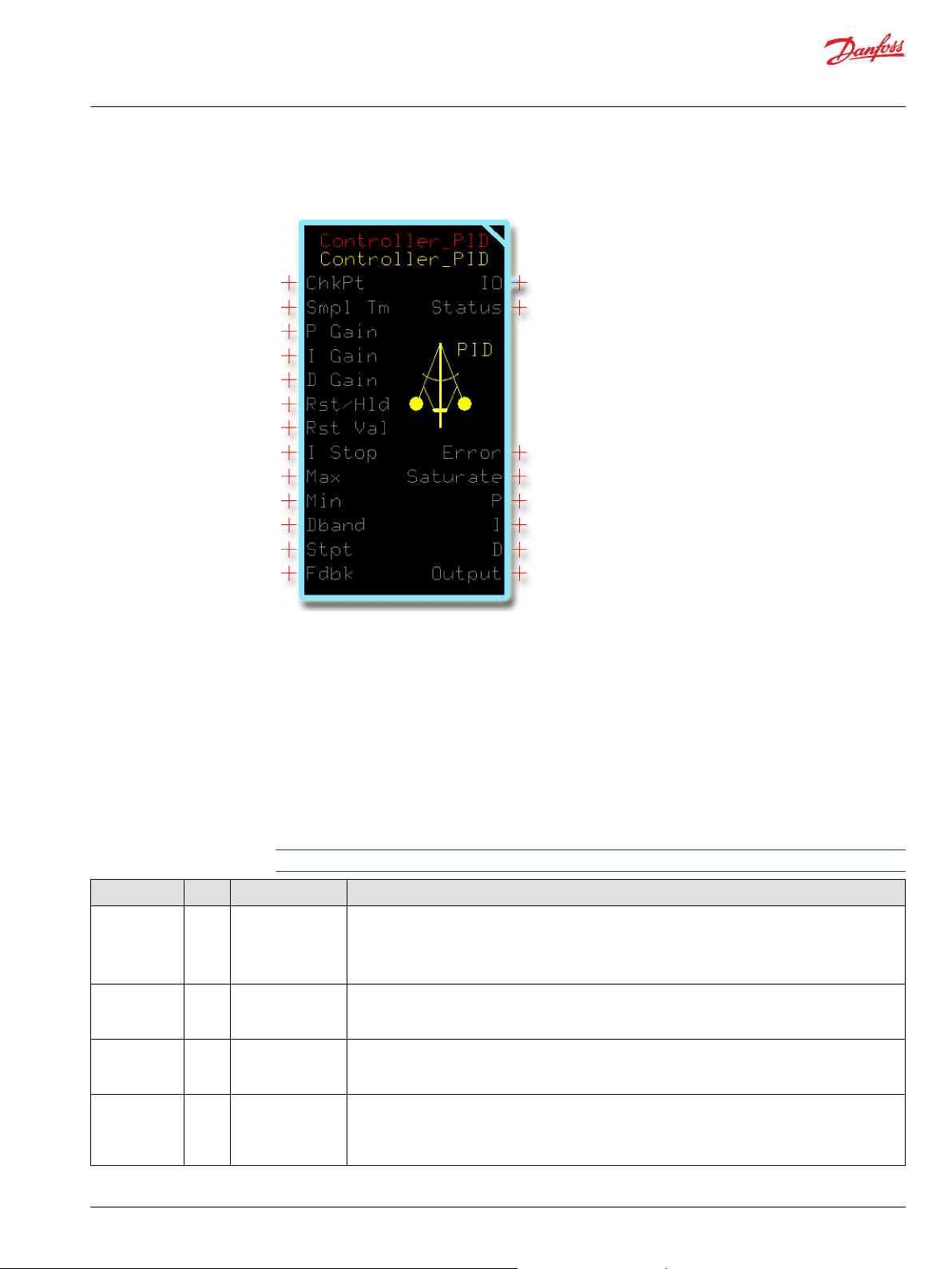
Controller_PID Function Block
Use the Controller_PID (Proportional, Integral, and Derivative) function block to control a closed-loop
application.
You can use this function block in:
•
Constant speed control applications.
•
Propel functions such as cruise control or straight tracking.
•
Work functions such as transit mixers.
The Controller_PI function block is available to implement closed-loop control through proportional and
integral (PI) functions. See Controller_PI Function Block. The Controller_PI function block uses less
memory than the Controller_PID function block.
Inputs
The inputs to the Controller_PID function block are described.
Use only the data types specified in this table. Other data types cause compiler errors.
Item Type Range Description
ChkPt BOOL ——
Smpl Tm U16 0–32767 Time between samples of the D Gain input. After ten samples, the function block calculates the
P Gain S16 -32768–32767 The proportional gain (P Gain) factor that determines how much the difference between Stpt and
I Gain S16 -32768–32767 The integral gain (I Gain) factor that determines how much the continual summing of the difference
True—include the function block’s built-in Advanced Checkpoint with Namespace in the compiled
•
LHX download file.
False—exclude the function block’s built-in Advanced Checkpoint with Namespace components
•
from the compiled LHX download file.
average error for the D Gain input.
1000 = 1000 ms
Fdbk influences the Output.
1000 = 1 (unity gain)
between Stpt and Fdbk influences the Output. Integration occurs on every process loop. I Gain
multiplies by OS.ExecTm to take account for processing time differences.
10000 = 1 (unity gain)
©
Danfoss | January 2019 11062085 | AQ284462219091en-000101 | 15
Page 16
User Manual
PLUS+1® Compliant Function Block Library—Control Function Blocks
Controller_PID Function Block
Item Type Range Description
D Gain S16 -32768–32767 The differential gain (D Gain) factor that determines how much the difference between the current
Stpt- Fdbk error and the previous Stpt-Fdbk error influences the Output.
100 = 1 (unity gain)
Rst/Hld U8 0–3 The reset/hold (Rst/Hld) setting:
0 = Normal operation—no reset or hold.
•
1 = Hold the integrator to the current values.
•
2 = Reset the integrator to the Rst Val.
•
3 = Reset the entire Output.
•
Rst Val S16 -32768–32767 The reset value (Rst Val) set in during a reset operation.
This item has no predefined unit value.
Assign the same unit values to Rst Val, I Stop, Max, Min, Dband, Stpt, Fdbk, Error, P, I, D, and Output.
I Stop U16 0–65535
Max S16 -32768–32767 The maximum allowed output value.
Min S16 -32768–32767 The minimum allowed output value.
Dband U16 0–65535
Stpt S16 -32768–32767 The system set point (Stpt). The desired system output.
Fdbk S16 -32768–32767 The system feedback (Fdbk). The actual, measured system output.
Sets the value at which the integral pauses where: Absolute (Stpt-Fdbk) > I_Stop.
Use to limit overshoot due to large steps changes in errors. To disable this feature, set I_Stop = 65535.
This item has no predefined unit value.
Assign the same unit values to Rst Val, I Stop, Max, Min, Dband, Stpt, Fdbk, Error, P, I, D, and Output.
When (P + I + D) > Max, the integrator holds and can only be reduced.
This item has no predefined unit value.
Assign the same unit values to Rst Val, I Stop, Max, Min, Dband, Stpt, Fdbk, Error, P, I, D, and Output.
When (P + I + D) < Min, the integrator holds and can only be increased.
This item has no predefined unit value.
Assign the same unit values to Rst Val, I Stop, Max, Min, Dband, Stpt, Fdbk, Error, P, I, D, and Output.
The allowed difference between Stpt and Fdbk before the function block begins error correction. The
function block makes no corrections until the error becomes greater than this value. The error used in
PID error calculation stays at zero until it becomes greater than the Dband value.
This item has no predefined unit value.
Assign the same unit values to Rst Val, I Stop, Max, Min, Dband, Stpt, Fdbk, Error, P, I, D, and Output.
This item has no predefined unit value.
Assign the same unit values to Rst Val, I Stop, Max, Min, Dband, Stpt, Fdbk, Error, P, I, D, and Output.
This item has no predefined unit value.
Assign the same unit values to Rst Val, I Stop, Max, Min, Dband, Stpt, Fdbk, Error, P, I, D, and Output.
Outputs
The outputs of the Controller_PID function block are described.
Item Type Range Description
IO Bus —— Outputs a bus with all of the function block's input and output signals.
The bus conveniently distributes this function block's signals to your application.
Status U16 —— Reports the status of the function block.
This output follows the standard bitwise scheme described in the Status topic.
Fault U16 —— Reports the faults of the function block.
This output follows the standard bitwise scheme described in the Fault topic.
Error S32 -65535–65535
Saturate
U8
0–2
The error or difference between the Stpt and the Fdbk.
This item has no predefined unit value.
Assign the same unit values to Rst Val, I Stop, Max, Min, Dband, Stpt, Fdbk, Error, P, I, D, and Output.
Output saturation indicator:
0 = No saturation.
•
1 = Down saturation. The function block’s Output value equals its Min value.
•
2 = Up saturation. The function block’s Output value equals its Max value.
•
16 | © Danfoss | January 2019 11062085 | AQ284462219091en-000101
Page 17
User Manual
PLUS+1® Compliant Function Block Library—Control Function Blocks
Controller_PID Function Block
Item Type Range Description
P S16 -32768–32767 The proportional calculation’s contribution to the Output.
P = (Stpt – Fdbk) * P Gain) / 1000
This item has no predefined unit value.
Assign the same unit values to Rst Val, I Stop, Max, Min, Dband, Stpt, Fdbk, Error, P, I, and Output.
I S16 -32768–32767 The integral calculation’s contribution to the Output.
I = Σ [(Stpt – Fdbk) * I Gain * OS.ExecTm)/10000]
This item has no predefined unit value.
Assign the same unit values to Rst Val, I Stop, Max, Min, Dband, Stpt, Fdbk, Error, P, I, and Output.
D S16 -32768–32767
Output S16 -32768–32767 Sum of the internal P, I and D values
The derivative calculation’s contribution to the Output.
D = [(Stpt – Fdbk)Current - (Stpt – Fdbk)Last] * D Gain/(Smpl_Tm * 1000)
• (Stpt – Fdbk)Current is the average of the most recent samples of Smpl_Tm/OS.ExecTm values.
• (Stpt – Fdbk)Last is the average of the last nine samples of Smpl_Tm/OS.ExecTm values.
This item has no predefined unit value.
Assign the same unit values to Rst Val, I Stop, Max, Min, Dband, Stpt, Fdbk, Error, P, I, D, and Output..
The sum of P, I and D may not equal Output because the function block:
• Calculates P, I and D as S32 data types and then restricts them to the S16 range before returning an
output.
• Calculates the Output before it restricts the P, I and D values to the S16 range.
• Bounds the Output to within a range defined by the Max and Min values.
This item has no predefined unit value.
Assign the same unit values to Rst Val, I Stop, Max, Min, Dband, Stpt, Fdbk, Error, P, I, D, and Output.
©
Danfoss | January 2019 11062085 | AQ284462219091en-000101 | 17
Page 18
User Manual
PLUS+1® Compliant Function Block Library—Control Function Blocks
Controller_PID Function Block
Function Block Connections
Connections you can make with the function block are described.
Description
Item
1.
2. Time between samples of the D Gain input.
3. The proportional gain (P Gain) factor that determines how much the Output is influenced by the difference in Stpt and Fdbk.
4. The integral gain (I Gain) factor that determines how much the Output is influenced by continual summing of the difference between Stpt
5. The differential gain (D Gain) factor that determines how much the difference between the current Stpt-Fdbk error and the previous Stpt-
6. The reset/hold (Rst/Hld) setting:
7.
8. Sets the value at which the integral pauses where: Absolute (Stpt-Fdbk) ≥ I_Stop.
9.
10.
11.
12.
13.
14. Outputs a bus with all of the function block's input and output signals.
15. Reports the status of the function block.
16. The error or difference between the Stpt and the Fdbk.
17. Output saturation indicator:
18.
19.
True—include the function block’s built-in Advanced Checkpoint with Namespace in the compiled LHX download file.
•
False—exclude the function block’s built-in Advanced Checkpoint with Namespace components from the compiled LHX download file.
•
and Fdbk.
Fdbk error influences the Output.
0 = Normal operation—no reset or hold.
•
1 = Hold the integrator to the current values.
•
2 = Reset the integrator to the Rst Val.
•
3 = Reset the entire Output.
•
The reset value (Rst Val) set during a reset operation.
The maximum allowed output value.
The minimum allowed output value.
The allowed difference between Stpt and Fdbk before the function block begins error correction.
The system set point (Stpt).
The system feedback (Fdbk).
0 = No saturation.
•
1 = Down saturation. The function block’s Output value equals its Min value.
•
2 = Up saturation. The function block’s Output value equals its Max value.
•
The proportional calculation’s contribution to the Output.
The integral calculation’s contribution to the Output.
18 | © Danfoss | January 2019 11062085 | AQ284462219091en-000101
Page 19
User Manual
PLUS+1® Compliant Function Block Library—Control Function Blocks
Controller_PID Function Block
Description
Item
20.
The derivative calculation’s contribution to the Output.
21.
Sum of the internal P, I, and D values.
Status Logic
This topic describes how status logic is indicated for the function block.
Condition Hex
Invalid setup. 0x8008 1000 Rst/Hld or Smpl Tm value is
*
Bit 16 set to 1 identifies a standard Danfoss status or fault code.
Identical Function Blocks Need Different Namespace Values to Successfully Compile
*
Binary Cause Response Correction
Either:
out of range.
Rst/Hld becomes 0.
•
Smpl Tm clamps at either
•
0 or 32767.
If you use the same function block more than once in an application, you must change each function
block’s namespace value to avoid compiler errors.
All function blocks contain Advanced Checkpoint with Namespace components that enable the PLUS+1
Service Tool to read block input and output values.
Some function blocks contain non-volatile memory components that store function block operating
parameters.
Both these components use memory names (“aliases”) to allocate memory. Identical memory names
cause compiler errors.
The namespace value adds a unique prefix to each component name to avoid errors. Keep each
namespace value short to save controller memory.
Return the Rst/Hld or Smpl Tm
value to within its expected
range.
®
Change Namespace Value
To successfully compile your application, change the namespace value for function blocks that are used
more than once in an application.
©
Danfoss | January 2019 11062085 | AQ284462219091en-000101 | 19
Page 20

User Manual
PLUS+1® Compliant Function Block Library—Control Function Blocks
Controller_PID Function Block
1. In the PLUS+1® GUIDE menu bar, click the Query/Change button.
2. Click on the function block whose namespace you want to set to a unique value.
The Edit Page window opens.
3. In the Edit Page window, enter a meaningful Namespace value.
Namespace values are case-sensitive.
•
To save controller memory, use a short namespace value.
•
4. Press Enter.
5. Repeat these steps to enter unique namespace values for other identical function blocks.
20 | © Danfoss | January 2019 11062085 | AQ284462219091en-000101
Page 21

User Manual
PLUS+1® Compliant Function Block Library—Control Function Blocks
Controller_PID Function Block
IEC 61508-3 Annex D Supplemental Information
The following table provides IEC 61508-3 Annex D supplemental information.
Item
Function block name Controller_PID.
Function block version 4.0.
Function block development
environment
Compatible hardware
Function block developed in
compliance with
Competence required of
function block integrator
Contacting Danfoss
Description
PLUS+1® GUIDE version 8.1 and later.
Verified in the PLUS+1® GUIDE compile process.
When the PLUS+1® GUIDE compiler finds a function block that is incompatible with hardware, it aborts the compile
process and logs an error message. The error message gives the location of the function block and states “Error 80:
component not supported in hwd.”
Danfoss Software Product Development Process (PDP), which includes ISO 9001 and IEC 61508-3 standards.
The knowledge, competence, and training required to:
Understand this manual.
•
Use the PLUS+1® GUIDE program to develop a machine control application.
•
Follow quality software practices to develop a machine control application.
•
https://www.danfoss.com/en/products/software/dps/plus1-software-services-support-and-training/plus1-support-andservices
©
Danfoss | January 2019 11062085 | AQ284462219091en-000101 | 21
Page 22
User Manual
PLUS+1® Compliant Function Block Library—Control Function Blocks
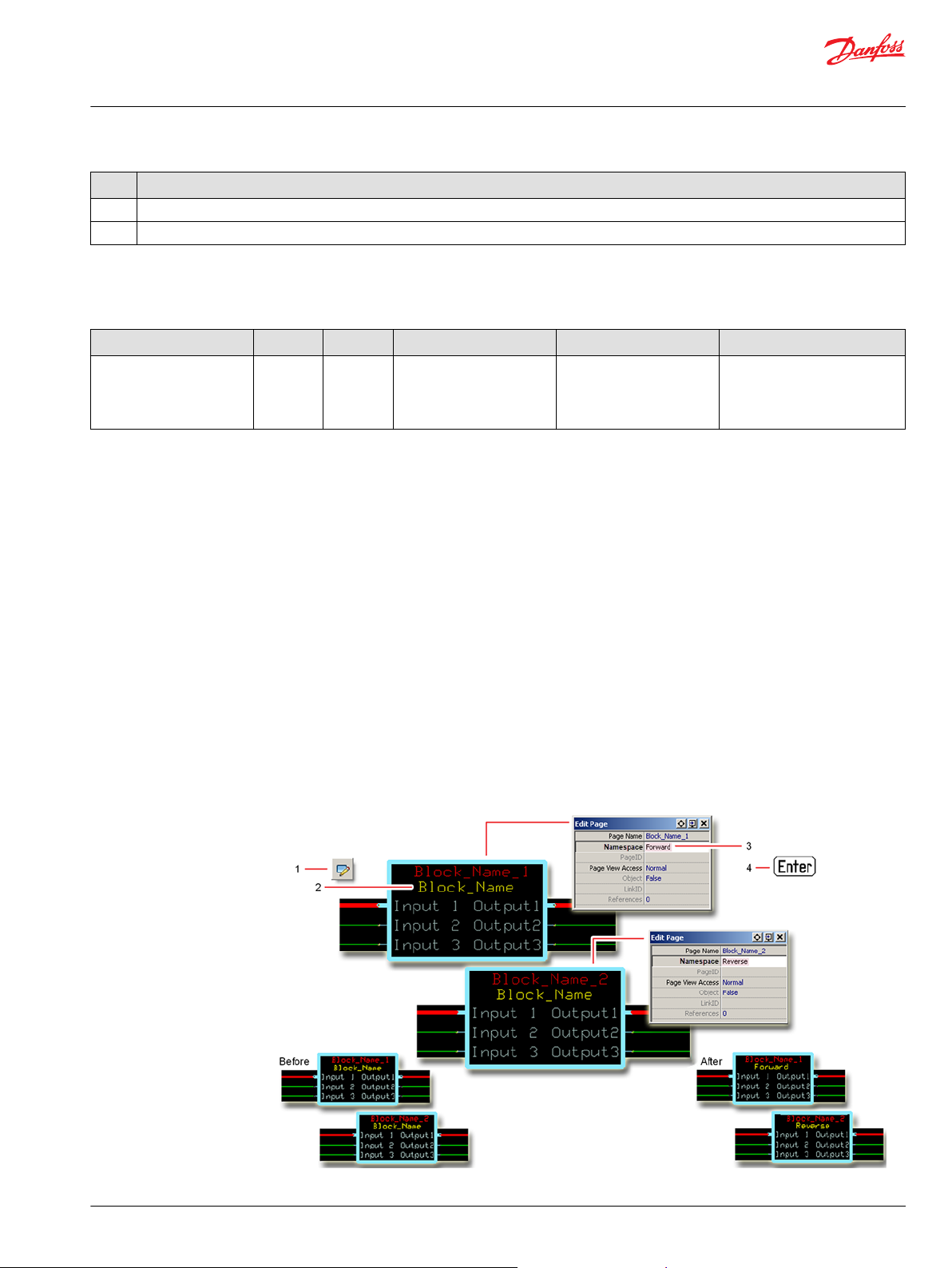
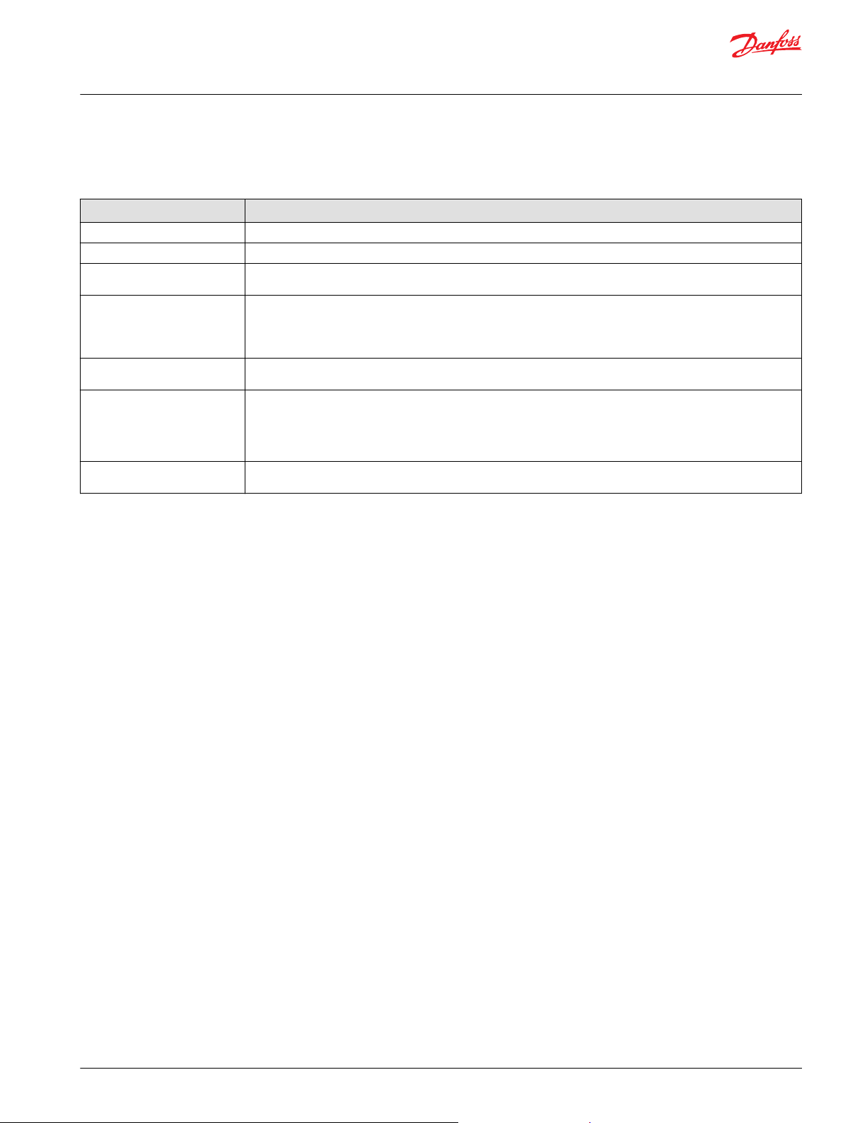
Profile_Knee Function Block
Use the Profile_Knee function block to change the curve characteristics of a signal.
One X-Y parameter pair along with fixed endpoints (X = 0, Y= 0 and X =10000, Y =10000) create a twosegment profile that defines how the function block’s Output values follow changes to its Input values.
Typically, you use this function block to:
Increase control resolution at slow speeds or low power output.
•
Linearize a sensor signal.
•
Create a non-linear control signal for a non-linear actuator.
•
When using this function block, note the following:
The function block’s Input and Output values can range from -10000 to 10000.
•
A change in the polarity of the function block’s Input values from positive to negative or from
•
negative to positive produces mirrored Output values.
Inputs
The inputs to the Profile_Knee function block are described.
Use only the data types specified in this table. Other data types cause compiler errors.
Item Type Range Description
ChkPt BOOL ——
X U16 1–9999 Scaling input parameter. When Input = X, Output = Y.
Y U16 0–10000 Scaling output parameter.
Input S16 -10000–10000 The input signal to be profiled.
True—include the function block’s built-in Advanced Checkpoint with Namespace in the compiled
•
LHX download file.
False—exclude the function block’s built-in Advanced Checkpoint with Namespace components
•
from the compiled LHX download file.
0 < X < 10000
When Input = X, Output = Y. When Input = -X, Output = -Y.
Outputs
The outputs of the Profile_Knee function block are described.
Item Type Range Description
IO Bus —— Outputs a bus with all of the function block's input and output signals.
The bus conveniently distributes this function block's signals to your application.
Status U16 —— Reports the status of the function block.
This output follows the standard bitwise scheme described in the Status topic.
Fault U16 —— Reports the faults of the function block.
This output follows the standard bitwise scheme described in the Fault topic.
Output S16 -10000–10000 The Input signal after profiling.
22 | © Danfoss | January 2019 11062085 | AQ284462219091en-000101
Page 23
User Manual
PLUS+1® Compliant Function Block Library—Control Function Blocks
Profile_Knee Function Block
Function Block Connections
Connections you can make with the function block are described.
Description
Item
1.
2. Input for X parameter.
3. Input for Y parameter.
4. The signal to be profiled.
5. Outputs a bus with all of the function block's input and output signals.
6. Reports the status of the function block.
7. Reports the faults of the function block.
8. The Input signal after profiling.
True—include the function block’s built-in Advanced Checkpoint with Namespace in the compiled LHX download file.
•
False—exclude the function block’s built-in Advanced Checkpoint with Namespace components from the compiled LHX download file.
•
The X-Y parameter pair profiles how the function block’s Output values follows changes to its Input values.
The X-Y parameter pair profiles how the function block’s Output values follows changes to its Input values.
©
Danfoss | January 2019 11062085 | AQ284462219091en-000101 | 23
Page 24
User Manual
PLUS+1® Compliant Function Block Library—Control Function Blocks
Profile_Knee Function Block
Function Block Example
Use the following example to understand how configuration and operation changes impact the output
of the function block.
24 | © Danfoss | January 2019 11062085 | AQ284462219091en-000101
Page 25
User Manual
PLUS+1® Compliant Function Block Library—Control Function Blocks
Profile_Knee Function Block
Symbol Description
Item
1. Fixed, software-defined profile point where:
X = 0
•
Y = 0
•
An Input value of 0 produces an Output value of 0.
2. User-defined profile point created by the parameter pair X-Y where:
X = 6000
•
Y = 2000
•
An Input value of 6000 produces an Output value of 2000.
3. Fixed, software-defined profile point where:
X = 10000
•
Y = 10000
•
An Input value of 0 produces an Output value of 0.
4. Negatively mirrors the user-defined profile point created by X-Y where:
X = -6000
•
Y = -2000
•
An Input value of -6000 produces an Output value of -2000.
5. Negatively mirrors the fixed profile where:
X = -10000
•
Y = -10000
•
An Input value of -10000 produces an Output value of -10000.
Status and Fault Logic
Use status and fault codes to determine proper program operation.
Status Logic
This topic describes how status logic is indicated for the function block.
Condition Hex
Invalid setup. 0x8008 1000
*
Bit 16 set to 1 identifies a standard Danfoss status or fault code.
*
Binary Cause Response Correction
X parameter is out-of-range. X parameter clamps at 9999
or 1.
Y parameter is out-of-range.
Y parameter holds at 10000.
Return the X parameter to within
its 1–9999 range.
Return the Y parameter to within
its 0–10000 range.
Fault Logic
This topic describes how fault logic is indicated for the function block.
Condition Hex
Input value is too low. 0x8001 0001 Input value < -10000. Output = -10000 Return the Input to the valid
Input value is too high. 0x8002 0010 Input value > 10000. Output = 10000
*
Bit 16 set to 1 identifies a standard Danfoss status or fault code.
*
Binary Cause Response Correction
range.
Identical Function Blocks Need Different Namespace Values to Successfully Compile
If you use the same function block more than once in an application, you must change each function
block’s namespace value to avoid compiler errors.
All function blocks contain Advanced Checkpoint with Namespace components that enable the PLUS+1
Service Tool to read block input and output values.
Some function blocks contain non-volatile memory components that store function block operating
parameters.
®
©
Danfoss | January 2019 11062085 | AQ284462219091en-000101 | 25
Page 26
User Manual
PLUS+1® Compliant Function Block Library—Control Function Blocks
Profile_Knee Function Block
Both these components use memory names (“aliases”) to allocate memory. Identical memory names
cause compiler errors.
The namespace value adds a unique prefix to each component name to avoid errors. Keep each
namespace value short to save controller memory.
Change Namespace Value
To successfully compile your application, change the namespace value for function blocks that are used
more than once in an application.
1. In the PLUS+1® GUIDE menu bar, click the Query/Change button.
2. Click on the function block whose namespace you want to set to a unique value.
The Edit Page window opens.
3. In the Edit Page window, enter a meaningful Namespace value.
Namespace values are case-sensitive.
•
To save controller memory, use a short namespace value.
•
4. Press Enter.
5. Repeat these steps to enter unique namespace values for other identical function blocks.
26 | © Danfoss | January 2019 11062085 | AQ284462219091en-000101
Page 27
User Manual
PLUS+1® Compliant Function Block Library—Control Function Blocks
Profile_Knee Function Block
IEC 61508-3 Annex D Supplemental Information
The following table provides IEC 61508-3 Annex D supplemental information.
Item
Function block name Profile_Knee.
Function block version 4.0.
Function block development
environment
Compatible hardware
Function block developed in
compliance with
Competence required of
function block integrator
Contacting Danfoss
Description
PLUS+1® GUIDE version 8.1 and later.
Verified in the PLUS+1® GUIDE compile process.
When the PLUS+1® GUIDE compiler finds a function block that is incompatible with hardware, it aborts the compile
process and logs an error message. The error message gives the location of the function block and states “Error 80:
component not supported in hwd.”
Danfoss Software Product Development Process (PDP), which includes ISO 9001 and IEC 61508-3 standards.
The knowledge, competence, and training required to:
Understand this manual.
•
Use the PLUS+1® GUIDE program to develop a machine control application.
•
Follow quality software practices to develop a machine control application.
•
https://www.danfoss.com/en/products/software/dps/plus1-software-services-support-and-training/plus1-support-andservices
©
Danfoss | January 2019 11062085 | AQ284462219091en-000101 | 27
Page 28
User Manual
PLUS+1® Compliant Function Block Library—Control Function Blocks
Profile_6Pt Function Block
Use the Profile_6Pt function block to change the curve characteristics of a signal.
Six X-Y parameter pairs create a seven-segment profile that define how the function block’s Output
values follow changes to its Input values.
Input values that are:
Less than the minimum X parameter produce Output values that follow the slope of the segment
•
produced by the X1-Y1 and X2-Y2 parameter pairs.
Greater than the maximum X parameter produce Output values that follow the slope of the segment
•
produced by the X5-Y5 and X6-Y6 parameter pairs.
You can use this function block to:
Increase control resolution at slow speeds or low-power output.
•
Linearize the signal from a sensor.
•
Create a non-linear control signal for a non-linear actuator.
•
When using this function block, note the following:
The function block’s Input and Output values can range from -32768 to 32767.
•
A change in the polarity of the function block’s Input values from positive to negative or from
•
negative to positive does not produce mirrored Output values.
Inputs
The inputs to the Profile_6pt function block are described.
Use only the data types specified in this table. Other data types cause compiler errors.
Item Type Range Description
ChkPt BOOL ——
Para Bus ——
X1 S16 -32768–32767 Scaling input parameter.
X2 S16 -32768–32767 Scaling input parameter.
X3 S16 -32768–32767 Scaling input parameter.
True—include the function block’s built-in Advanced Checkpoint with Namespace in the compiled
•
LHX download file.
False—exclude the function block’s built-in Advanced Checkpoint with Namespace components
•
from the compiled LHX download file.
Input for six X-Y parameter pairs.
These pairs profile how the function block’s Output values follows changes to its Input values.
When Input = X1, Output = Y1.
-32768 ≤ X1 < X2 < X3 < X4 < X5 < X6 ≤ 32767
When Input = X2, Output = Y2.
-32768 ≤ X1 < X2 < X3 < X4 < X5 < X6 ≤ 32767
When Input = X3, Output = Y3.
-32768 ≤ X1 < X2 < X3 < X4 < X5 < X6 ≤ 32767
28 | © Danfoss | January 2019 11062085 | AQ284462219091en-000101
Page 29
User Manual
PLUS+1® Compliant Function Block Library—Control Function Blocks
Profile_6Pt Function Block
Item Type Range Description
X4 S16 -32768–32767 Scaling input parameter.
When Input = X4, Output = Y4.
-32768 ≤ X1 < X2 < X3 < X4 < X5 < X6 ≤ 32767
X5 S16 -32768–32767 Scaling input parameter.
When Input = X5, Output = Y5.
-32768 ≤ X1 < X2 < X3 < X4 < X5 < X6 ≤ 32767
X6 S16 -32768–32767 Scaling input parameter.
When Input = X6, Output = Y6.
-32768 ≤ X1 < X2 < X3 < X4 < X5 < X6 ≤ 32767
Y1 S16 -32768–32767 Scaling output parameter.
When Input = X1, Output = Y1.
Y values can increase, decrease, or stay the same.
Y2 S16 -32768–32767 Scaling output parameter.
When Input = X2, Output = Y2.
Y values can increase, decrease, or stay the same.
Y3 S16 -32768–32767 Scaling output parameter.
When Input = X3, Output = Y3.
Y values can increase, decrease, or stay the same.
Y4 S16 -32768–32767 Scaling output parameter.
When Input = X4, Output = Y4.
Y values can increase, decrease, or stay the same.
Y5 S16 -32768–32767 Scaling output parameter.
When Input = X5, Output = Y5.
Y values can increase, decrease, or stay the same.
Y6 S16 -32768–32767 Scaling output parameter.
When Input = X6, Output = Y6.
Y values can increase, decrease, or stay the same.
Input S16 -32768–32767 The input signal to be profiled.
Outputs
The outputs of the Profile_6Pt function block are described.
Item Type Range Description
IO Bus —— Outputs a bus with all of the function block's input and output signals.
The bus conveniently distributes this function block's signals to your application.
Status U16 —— Reports the status of the function block.
This output follows the standard bitwise scheme described in the Status topic.
Fault U16 —— Reports the faults of the function block.
This output follows the standard bitwise scheme described in the Fault topic.
Output S16 -10000–10000 The Input signal after profiling.
Function Block Connections
Connections you can make with the function block are described.
©
Danfoss | January 2019 11062085 | AQ284462219091en-000101 | 29
Page 30

User Manual
PLUS+1® Compliant Function Block Library—Control Function Blocks
Profile_6Pt Function Block
Description
Item
1.
2. Input for six X-Y parameter pairs.
3. The signal to be profiled.
4. Outputs a bus with all of the function block's input and output signals.
5. Reports the status of the function block.
6. The Input signal after profiling.
Function Block Example
True—include the function block’s built-in Advanced Checkpoint with Namespace in the compiled LHX download file.
•
False—exclude the function block’s built-in Advanced Checkpoint with Namespace components from the compiled LHX download file.
•
These pairs profile how the function block’s Output follows changes to its Input values.
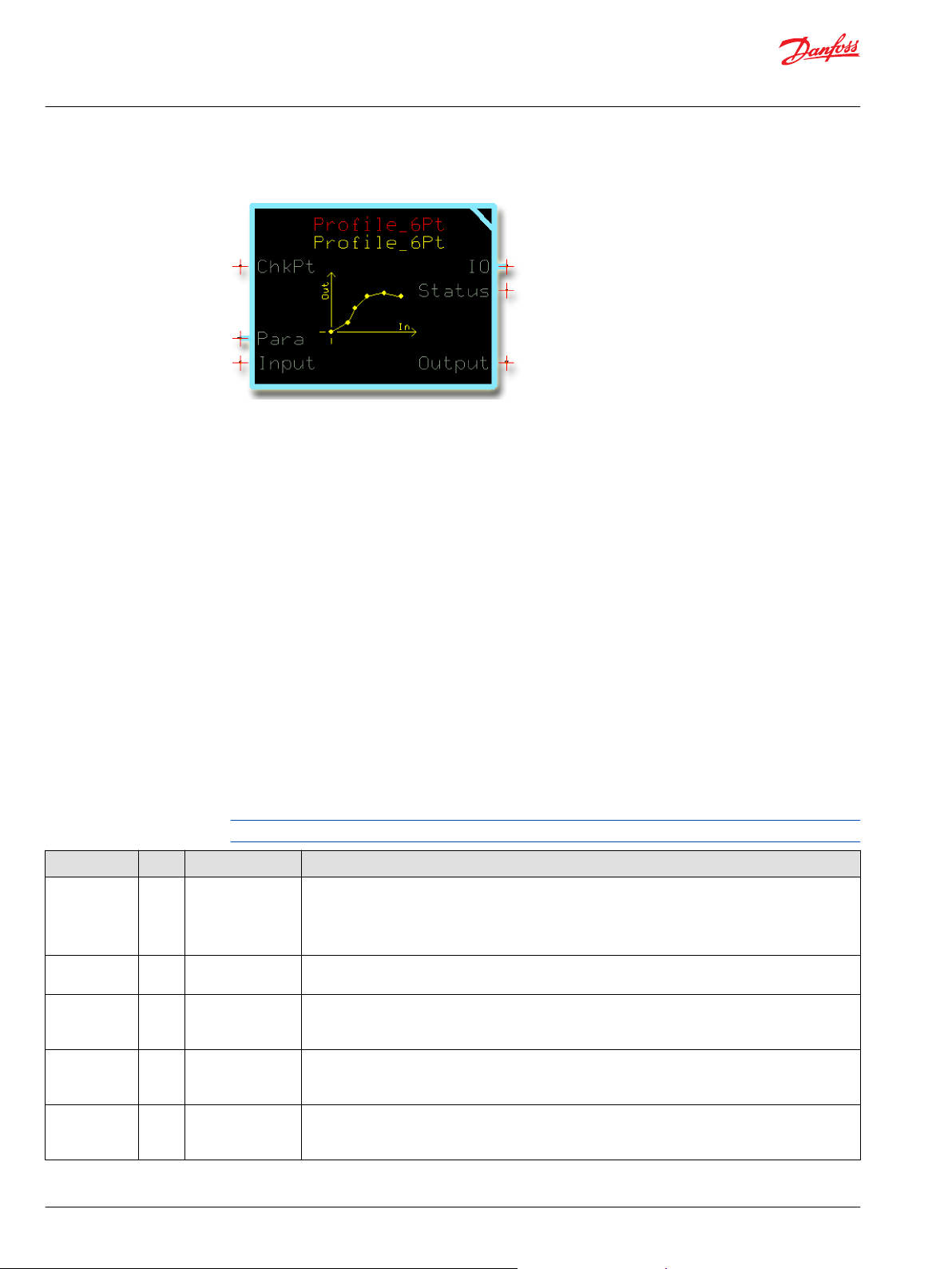
Use the following example to understand how configuration changes impact the output of the function
block.
Symbol Description
Item
1. Profile point created by parameter pair X1-Y1 where:
X1 = 0
•
Y1 = 0
•
An Input value of 0 produces an Output value of 0.
2. Profile point created by parameter pair X2-Y2 where:
X2 = 500
•
Y2 = 125
•
An Input value of 500 produces an Output value of 125.
3. Profile point created by parameter pair X3-Y3 where:
X3 = 1000
•
Y3 = 1000
•
An Input value of 1000 produces an Output value of 1000.
4. Profile point created by parameter pair X4-Y4 where:
X4 = 2000
•
Y4 = 1250
•
An Input value of 2000 produces an Output value of 1250.
30 | © Danfoss | January 2019 11062085 | AQ284462219091en-000101
Page 31

User Manual
PLUS+1® Compliant Function Block Library—Control Function Blocks
Profile_6Pt Function Block
Symbol Description
Item
5. Profile point created by parameter pair X5-Y5 where:
X5 = 2250
•
Y5 = 2000
•
An Input value of 2250 produces an Output value of 2000.
6. Profile point created by parameter pair X6-Y6 where:
X6 = 3000
•
Y6 = 2250
•
An Input value of 3000 produces an Output value of 2250.
7. Slope extrapolated from the slope created by parameter pairs X5-Y5 and X6-Y6.
Input values that are greater than 3000 produce Output values that follow this slope.
The S16 data type sets the limits to the maximum Input values and the maximum Output values.
8. Slope extrapolated from the slope created by parameter pairs X1-Y1 and X2-Y2.
Input values that are less than 0 produce Output values that follow this slope.
The S16 data type sets the limits to the maximum Input values and the maximum Output values.
Status Logic
This topic describes how status logic is indicated for the function block.
Condition Hex
Invalid setup. 0x8008 1000 X1-X6 parameters do not
*
Bit 16 set to 1 identifies a standard Danfoss status or fault code.
*
Binary Cause Response Correction
Output = 0. Successively increase X
successively increase in
value.
parameter values.
Identical Function Blocks Need Different Namespace Values to Successfully Compile
If you use the same function block more than once in an application, you must change each function
block’s namespace value to avoid compiler errors.
All function blocks contain Advanced Checkpoint with Namespace components that enable the PLUS+1
Service Tool to read block input and output values.
Some function blocks contain non-volatile memory components that store function block operating
parameters.
Both these components use memory names (“aliases”) to allocate memory. Identical memory names
cause compiler errors.
The namespace value adds a unique prefix to each component name to avoid errors. Keep each
namespace value short to save controller memory.
®
©
Danfoss | January 2019 11062085 | AQ284462219091en-000101 | 31
Page 32

User Manual
PLUS+1® Compliant Function Block Library—Control Function Blocks
Profile_6Pt Function Block
Change Namespace Value
To successfully compile your application, change the namespace value for function blocks that are used
more than once in an application.
1. In the PLUS+1® GUIDE menu bar, click the Query/Change button.
2. Click on the function block whose namespace you want to set to a unique value.
The Edit Page window opens.
3. In the Edit Page window, enter a meaningful Namespace value.
Namespace values are case-sensitive.
•
To save controller memory, use a short namespace value.
•
4. Press Enter.
5. Repeat these steps to enter unique namespace values for other identical function blocks.
32 | © Danfoss | January 2019 11062085 | AQ284462219091en-000101
Page 33

User Manual
PLUS+1® Compliant Function Block Library—Control Function Blocks
Profile_6Pt Function Block
IEC 61508-3 Annex D Supplemental Information
The following table provides IEC 61508-3 Annex D supplemental information.
Item
Function block name Profile_6Pt.
Function block version 4.0.
Function block development
environment
Compatible hardware
Function block developed in
compliance with
Competence required of
function block integrator
Contacting Danfoss
Description
PLUS+1® GUIDE version 8.1 and later.
Verified in the PLUS+1® GUIDE compile process.
When the PLUS+1® GUIDE compiler finds a function block that is incompatible with hardware, it aborts the compile
process and logs an error message. The error message gives the location of the function block and states “Error 80:
component not supported in hwd.”
Danfoss Software Product Development Process (PDP), which includes ISO 9001 and IEC 61508-3 standards.
The knowledge, competence, and training required to:
Understand this manual.
•
Use the PLUS+1® GUIDE program to develop a machine control application.
•
Follow quality software practices to develop a machine control application.
•
https://www.danfoss.com/en/products/software/dps/plus1-software-services-support-and-training/plus1-support-andservices
©
Danfoss | January 2019 11062085 | AQ284462219091en-000101 | 33
Page 34

User Manual
PLUS+1® Compliant Function Block Library—Control Function Blocks
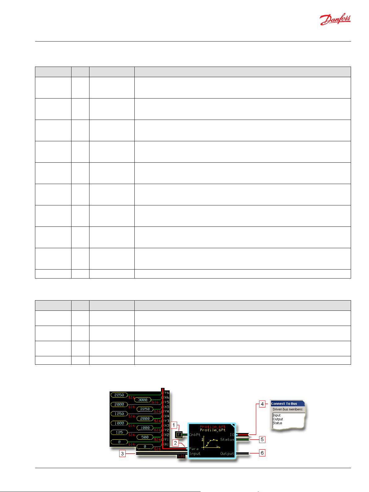
Profile_8Pt Function Block
Use the Profile_8Pt function block to change the curve characteristics of a signal.
Six X-Y parameter pairs along with fixed endpoints (X = 0, Y= 0 and X =10000, Y =10000) create a sevensegment profile that defines how the function block’s Output values follow changes to its Input values.
You can use this function block to:
Increase control resolution at slow speeds or low-power output.
•
Linearize the signal from a sensor.
•
Create a non-linear control signal for a non-linear actuator.
•
When using this function block, note the following:
The function block’s Input and Output values can range from -10000 to 10000.
•
A change in the polarity of the function block’s Input values from positive to negative or from
•
negative to positive produces mirrored Output values.
Inputs
The inputs to the Profile_8Pt function block are described.
Use only the data types specified in this table. Other data types cause compiler errors.
Item Type Range Description
ChkPt BOOL ——
Para Bus ——
X1 U16 1–9999 Scaling input parameter.
X2 U16 1–9999 Scaling input parameter.
X3 U16 1–9999 Scaling input parameter.
X4 U16 1–9999 Scaling input parameter.
X5 U16 1–9999 Scaling input parameter.
True—include the function block’s built-in Advanced Checkpoint with Namespace in the compiled
•
LHX download file.
False—exclude the function block’s built-in Advanced Checkpoint with Namespace components
•
from the compiled LHX download file.
When Input = X1, Output = Y1.
0 < X1 < X2 < X3 < X4 < X5 < X6 < 10000
When Input = X2, Output = Y2.
0 < X1 < X2 < X3 < X4 < X5 < X6 < 10000
When Input = X3, Output = Y3.
0 < X1 < X2 < X3 < X4 < X5 < X6 < 10000
When Input = X4, Output = Y4.
0 < X1 < X2 < X3 < X4 < X5 < X6 < 10000
When Input = X5, Output = Y5.
0 < X1 < X2 < X3 < X4 < X5 < X6 < 10000
34 | © Danfoss | January 2019 11062085 | AQ284462219091en-000101
Page 35
User Manual
PLUS+1® Compliant Function Block Library—Control Function Blocks
Profile_8Pt Function Block
Item Type Range Description
X6 U16 1–9999 Scaling input parameter.
When Input = X6, Output = Y6.
0 < X1 < X2 < X3 < X4 < X5 < X6 < 10000
Y1 U16 0–10000 Scaling output parameter.
When Input = X1, Output = Y1.
Y values can increase, decrease, or stay the same.
Y2 U16 0–10000 Scaling output parameter.
When Input = X2, Output = Y2.
Y values can increase, decrease, or stay the same.
Y3 U16 0–10000 Scaling output parameter.
When Input = X3, Output = Y3.
Y values can increase, decrease, or stay the same.
Y4 U16 0–10000 Scaling output parameter.
When Input = X4, Output = Y4.
Y values can increase, decrease, or stay the same.
Y5 U16 0–10000 Scaling output parameter.
When Input = X5, Output = Y5.
Y values can increase, decrease, or stay the same.
Y6 U16 0–10000 Scaling output parameter.
When Input = X6, Output = Y6.
Y values can increase, decrease, or stay the same.
Input S16 -10000–10000 The input signal to be profiled.
Outputs
The outputs of the Profile_8Pt function block are described.
Item Type Range Description
IO Bus —— Outputs a bus with all of the function block's input and output signals.
The bus conveniently distributes this function block's signals to your application.
Status U16 —— Reports the status of the function block.
This output follows the standard bitwise scheme described in the Status topic.
Fault U16 —— Reports the faults of the function block.
This output follows the standard bitwise scheme described in the Fault topic.
Output S16 -10000–10000 The Input signal after profiling.
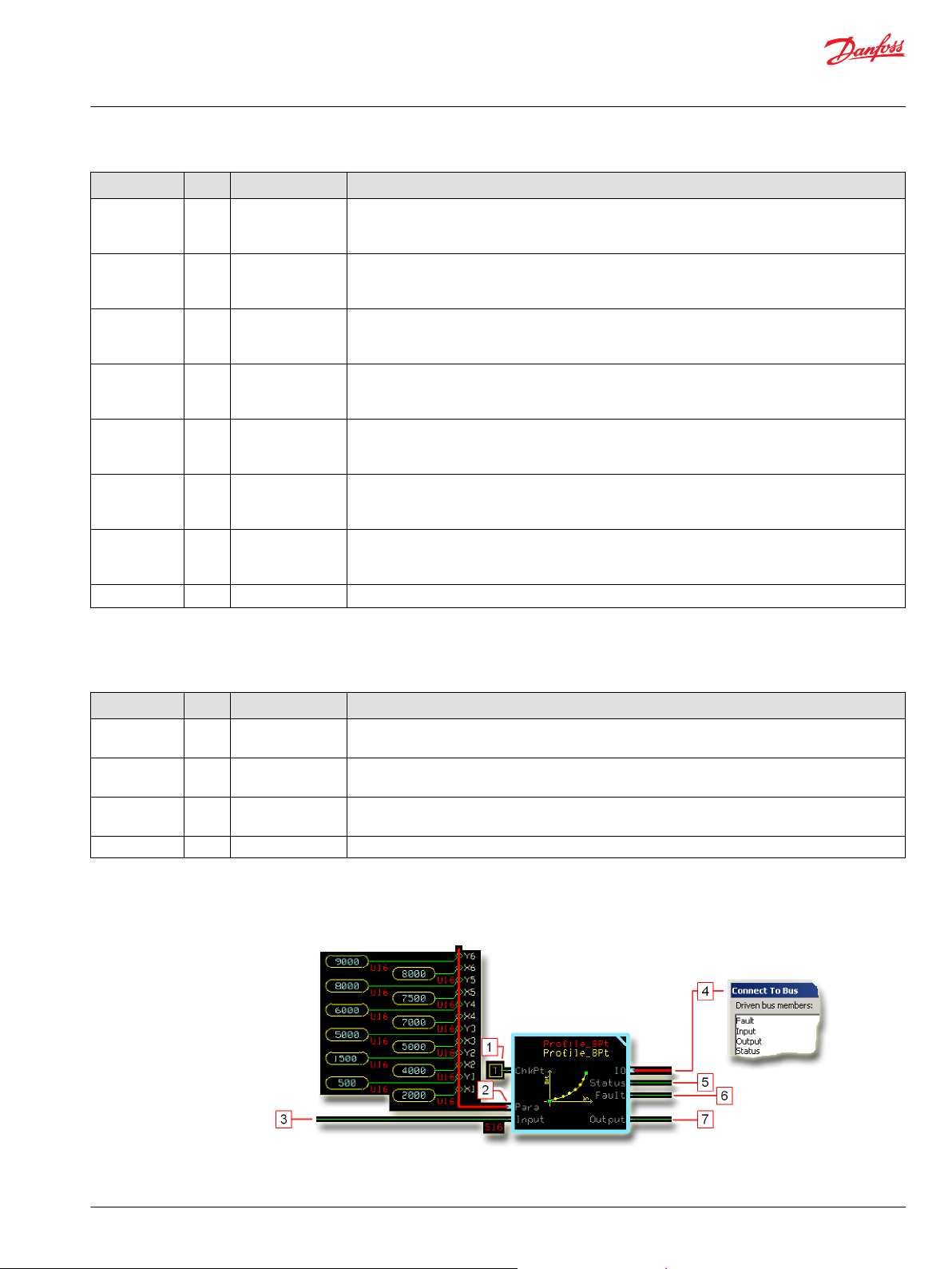
Function Block Connections
Connections you can make with the function block are described.
©
Danfoss | January 2019 11062085 | AQ284462219091en-000101 | 35
Page 36
User Manual
PLUS+1® Compliant Function Block Library—Control Function Blocks
Profile_8Pt Function Block
Description
Item
1.
2. Input for six X-Y parameter pairs.
3. The signal to be profiled.
4. Outputs a bus with all of the function block's input and output signals.
5. Reports the status of the function block.
6. Reports the faults of the function block.
7. The Input signal after profiling.
True—include the function block’s built-in Advanced Checkpoint with Namespace in the compiled LHX download file.
•
False—exclude the function block’s built-in Advanced Checkpoint with Namespace components from the compiled LHX download file.
•
These pairs profile how the function block’s Output follows changes to its Input values.
36 | © Danfoss | January 2019 11062085 | AQ284462219091en-000101
Page 37
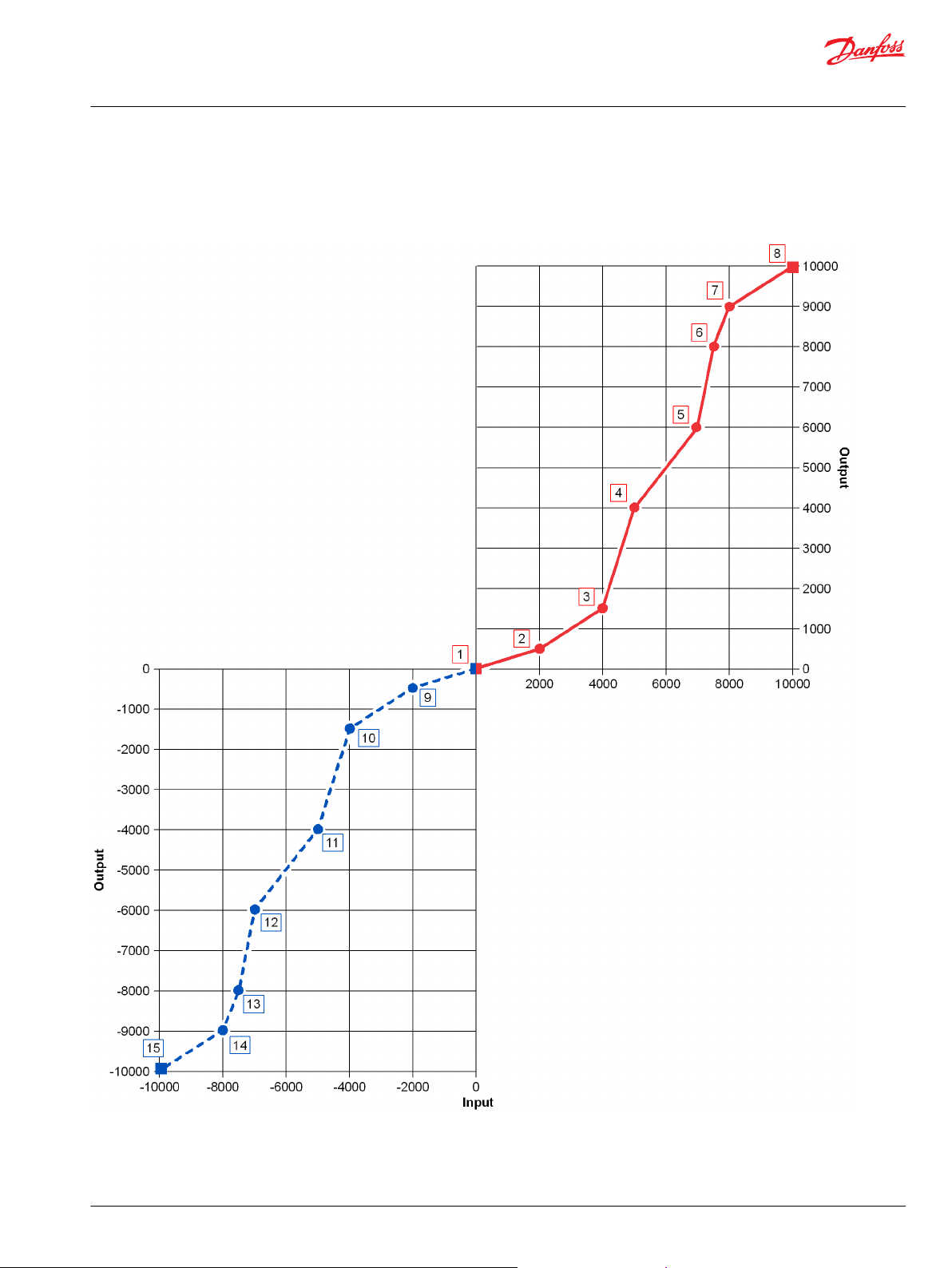
User Manual
PLUS+1® Compliant Function Block Library—Control Function Blocks
Profile_8Pt Function Block
Function Block Example
Use the following example to understand how configuration changes impact the output of the function
block.
©
Danfoss | January 2019 11062085 | AQ284462219091en-000101 | 37
Page 38
User Manual
PLUS+1® Compliant Function Block Library—Control Function Blocks
Profile_8Pt Function Block
Figure Details
Symbol Description
Item
1. Fixed, software-defined profile point where:
X = 0
•
Y = 0
•
An Input value of 0 produces an Output value of 0.
2. User-defined profile point created by the parameter pair X1-Y1 where:
X1 = 2000
•
Y1 = 500
•
An Input value of 5=2000 produces an Output value of 500.
3. Profile point created by parameter pair X2-Y2 where:
X2 = 4000
•
Y2 = 1500
•
An Input value of 4000 produces an Output value of 1500.
4. Profile point created by parameter pair X3-Y3 where:
X3 = 5000
•
Y3 = 4000
•
An Input value of 5000 produces an Output value of 4000.
5. Profile point created by parameter pair X4-Y4 where:
X4 = 7000
•
Y4 = 6000
•
An Input value of 7000 produces an Output value of 6000.
6. Profile point created by parameter pair X5-Y5 where:
X5 = 7500
•
Y5 = 8000
•
An Input value of 7500 produces an Output value of 8000.
7. Profile point created by parameter pair X6-Y6 where:
X6 = 8000
•
Y6 = 9000
•
An Input value of 8000 produces an Output value of 9000.
8. Fixed, software-defined profile point where:
X = 10000
•
Y = 10000
•
An Input value of 10000 produces an Output value of 10000.
9. Negatively mirrors the user-defined profile point created by the parameter pair X1-Y1 where:
-X1 = -2000
•
-Y1 = -500
•
An Input value of -2000 produces an Output value of -500.
10. Negatively mirrors the user-defined profile point created by the parameter pair X2-Y2 where:
-X2 = -4000
•
-Y2 = -1500
•
An Input value of -4000 produces an Output value of -1500.
11. Negatively mirrors the user-defined profile point created by the parameter pair X3-Y3 where:
-X3 = -5000
•
-Y3 = -4000
•
An Input value of -5000 produces an Output value of -4000.
12. Negatively mirrors the user-defined profile point created by the parameter pair X4-Y4 where:
-X4 = -7000
•
-Y4 = -6000
•
An Input value of -7000 produces an Output value of -6000.
38 | © Danfoss | January 2019 11062085 | AQ284462219091en-000101
Page 39

User Manual
PLUS+1® Compliant Function Block Library—Control Function Blocks
Profile_8Pt Function Block
Figure Details (continued)
Symbol Description
Item
13. Negatively mirrors the user-defined profile point created by the parameter pair X5-Y5 where:
-X5 = -7500
•
-Y5 = -8000
•
An Input value of -7500 produces an Output value of -8000.
14. Negatively mirrors the user-defined profile point created by the parameter pair X6-Y6 where:
-X6 = -8000
•
-Y6 = -9000
•
An Input value of -8000 produces an Output value of -9000.
15. Negatively mirrors the fixed profile point where:
X = -10000
•
Y = -10000
•
An Input value of -10000 produces an Output value of -10000.
Status and Fault Logic
Use status and fault codes to determine proper program operation.
Status Logic
This topic describes how status logic is indicated for the function block.
Condition Hex
Invalid setup. 0x8008 1000
*
Bit 16 set to 1 identifies a standard Danfoss status or fault code.
*
Binary Cause Response Correction
One or more Y parameters is
out-of-range.
X1–X6 parameters do not
successively increase in
value. parameter is out-ofrange.
X1 is less than 1 or X6 is
greater than 9999.
Out-of-range Y parameters
clamp at 10000.
Output = 0.
X1 clamps at 1 and X6
clamps at 9999.
Return Y parameters to within
their 0–10000 range.
Successively increase X
parameter values.
Return the X1 and X6 values to
within their 1–9999 range.
Fault Logic
This topic describes how fault logic is indicated for the function block.
Condition Hex
Input value is too low. 0x8001 0001 Input value < -10000. Output = -10000 Return the Input to the valid
Input value is too high. 0x8002 0010 Input value > 10000. Output = 10000
*
Bit 16 set to 1 identifies a standard Danfoss status or fault code.
*
Binary Cause Response Correction
range.
Identical Function Blocks Need Different Namespace Values to Successfully Compile
If you use the same function block more than once in an application, you must change each function
block’s namespace value to avoid compiler errors.
All function blocks contain Advanced Checkpoint with Namespace components that enable the PLUS+1
Service Tool to read block input and output values.
Some function blocks contain non-volatile memory components that store function block operating
parameters.
Both these components use memory names (“aliases”) to allocate memory. Identical memory names
cause compiler errors.
®
©
Danfoss | January 2019 11062085 | AQ284462219091en-000101 | 39
Page 40
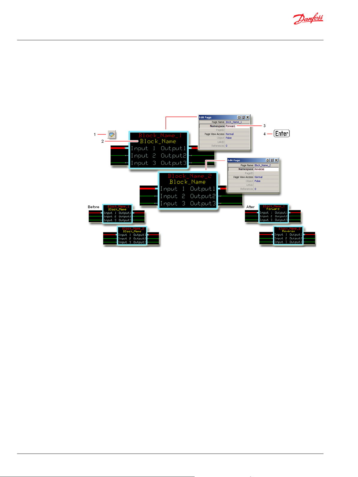
User Manual
PLUS+1® Compliant Function Block Library—Control Function Blocks
Profile_8Pt Function Block
The namespace value adds a unique prefix to each component name to avoid errors. Keep each
namespace value short to save controller memory.
Change Namespace Value
To successfully compile your application, change the namespace value for function blocks that are used
more than once in an application.
1. In the PLUS+1® GUIDE menu bar, click the Query/Change button.
2. Click on the function block whose namespace you want to set to a unique value.
The Edit Page window opens.
3. In the Edit Page window, enter a meaningful Namespace value.
Namespace values are case-sensitive.
•
To save controller memory, use a short namespace value.
•
4. Press Enter.
5. Repeat these steps to enter unique namespace values for other identical function blocks.
40 | © Danfoss | January 2019 11062085 | AQ284462219091en-000101
Page 41

User Manual
PLUS+1® Compliant Function Block Library—Control Function Blocks
Profile_8Pt Function Block
IEC 61508-3 Annex D Supplemental Information
The following table provides IEC 61508-3 Annex D supplemental information.
Item
Function block name Profile_8Pt.
Function block version 4.0.
Function block development
environment
Compatible hardware
Function block developed in
compliance with
Competence required of
function block integrator
Contacting Danfoss
Description
PLUS+1® GUIDE version 8.1 and later.
Verified in the PLUS+1® GUIDE compile process.
When the PLUS+1® GUIDE compiler finds a function block that is incompatible with hardware, it aborts the compile
process and logs an error message. The error message gives the location of the function block and states “Error 80:
component not supported in hwd.”
Danfoss Software Product Development Process (PDP), which includes ISO 9001 and IEC 61508-3 standards.
The knowledge, competence, and training required to:
Understand this manual.
•
Use the PLUS+1® GUIDE program to develop a machine control application.
•
Follow quality software practices to develop a machine control application.
•
https://www.danfoss.com/en/products/software/dps/plus1-software-services-support-and-training/plus1-support-andservices
©
Danfoss | January 2019 11062085 | AQ284462219091en-000101 | 41
Page 42

User Manual
PLUS+1® Compliant Function Block Library—Control Function Blocks
Comparison of 6Pt, 8Pt, and Profile_Knee Function Blocks
Use the comparison table to determine which function block you want to use in your application.
Function Block Input Value Range Output Value Range Segments In Profile Negative Input Produces Negative Mirrored
Output?
Profile_6Pt -32768–32767 -32768–32767 7 No.
Profile_8Pt -10000–10000 -10000–10000 7 Yes.
Profile_Knee -10000–10000 -10000–10000 2 Yes.
*
Input values that are less than the minimum X parameter produce Output values that follow the slope of the segment produced by the X1-Y1 and
X2-Y2 parameter pairs. Input values that are greater than the maximum X parameter produce Output values that follow the slope of the segment
produced by the X5-Y5 and X6-Y6 parameter pairs.
*
42 | © Danfoss | January 2019 11062085 | AQ284462219091en-000101
Page 43

User Manual
PLUS+1® Compliant Function Block Library—Control Function Blocks
Ackermann Function Block
Use the Ackermann function block to calculate the wheel speeds and wheel angles for a given average
steering command input and vehicle speed command input.
You can use this function block to calculate wheel angles and wheel speeds:
For four-wheel propel applications that independently control the speed of two or four wheels.
•
To determine the expected wheel speed when detecting wheel spin.
•
Inputs
The inputs to the Ackerman function block are described.
Use only the data types specified in this table. Other data types cause compiler errors.
Item Type Range Description
ChkPt BOOL ——
Spd S16 -20000–20000
Ang S16 -9000–9000
Wdth U16 200–10000
Lgth U16 800–20000
MaxWhlSpd U16 0–20000
MaxWhlAng U16 0–9000
True—include the function block’s built-in Advanced Checkpoint with Namespace
False—exclude the function block’s built-in Advanced Checkpoint with Namespace components
from the compiled LHX download file.
Requested vehicle speed.
1000 = 1000 mm/s
Requested steering angle.
1000 = 10.00°
Width of the vehicle’s wheelbase.
1000 = 1000 mm
Length of vehicle's wheelbase.
1 = 1 mm
Maximum allowed wheel speed in both a positive and a negative direction. Once one wheel reaches
the MaxWhlSpd, the wheel speeds of the other wheels stop increasing.
1000 = 1000 mm/s
The maximum allowed wheel steering angle in both a positive and a negative direction. Once one
wheel reaches the MaxWhlAng, the wheel angles of the other wheels stop increasing.
1000 = 10.00º
©
Danfoss | January 2019 11062085 | AQ284462219091en-000101 | 43
Page 44

User Manual
PLUS+1® Compliant Function Block Library—Control Function Blocks
Ackermann Function Block
Item Type Range Description
Wdth Ofst S16 -10000–10000 Width offset for the center of rotation when steering.
A positive Wdth Ofst value shifts the center of rotation when steering to the right of the vehicle.
•
A negative Wdth Ofst value shifts the center of rotation when steering to the left of the vehicle.
•
Use the Wdth Ofst to shift your vehicle’s center of rotation when steering if:
You attach an implement to the left or right side of your vehicle.
•
Your vehicle’s wheelbase does not determine the center of rotation when steering.
•
If your vehicle’s wheelbase determines the center of rotation when steering, set the Wdth Ofst value to
0.
1000 = 1000 mm
Lgth Ofst S16 -10000–10000
Strg Mode U8 1–4 Vehicle steering mode:
Length offset for the center of rotation when steering.
A positive Lgth Ofst value shifts the center of rotation when steering toward the front of the vehicle.
•
A negative Lgth Ofst value shifts the center of rotation when steering toward the rear of the vehicle.
•
Use the Lgth Ofst to shift your vehicle’s center of rotation when steering if:
You attach an implement to the front or rear of your vehicle.
•
Your vehicle’s wheelbase does not determine the center of rotation when steering.
•
If your vehicle’s wheelbase determines the center of rotation when steering, set the Wdth Ofst value to
0.
1000 = 1000 mm
1 = Two-wheel front-steering.
•
2 = Two-wheel rear-steering.
•
3 = Four-wheel coordinated-steering.
•
4 = Four-wheel crab-steering.
•
Outputs
The outputs of the Ackermann function block are described.
Item Type Range Description
IO Bus —— Outputs a bus with all of the function block's input and output signals.
This bus provides a convenient way to distribute this function block's signals to your application.
Status U16 —— Reports the status of the function block.
This output follows the standard bitwise scheme described in the Status Logic topic.
Fault U16 —— Reports the faults of the function block.
This output follows the standard bitwise scheme described in the Status Logic topic.
MaxStrgAng U16 0–9000 The maximum effective Ang input in both a positive and a negative direction.
Any Ang inputs above this value cause no change increase in wheel angles.
The function block calculates this output based on maximum allowed wheel angles and vehicle
geometry.
1000 = 10.00º
WhlSpd Bus —— Outputs a bus with calculated wheel speed signals for the left-front, right-front, left-rear, and right-rear
LF S16 -20000–20000 Calculated wheel speed for the left-front wheel.
RF S16 -20000–20000 Calculated wheel speed for the right-front wheel.
LR S16 -20000–20000 Calculated wheel speed for the left-rear wheel.
RR S16 -20000–20000 Calculated wheel speed for the right-rear wheel.
WhlAng Bus —— Outputs a bus with calculated wheel angle signals for the left-front, right-front, left-rear, and right-rear
LF S16 -9000–9000 Calculated wheel angle for the left-front wheel.
wheels.
1000 = 1000 mm/s
1000 = 1000 mm/s
1000 = 1000 mm/s
1000 = 1000 mm/s
wheels.
1000 = 10.00º
44 | © Danfoss | January 2019 11062085 | AQ284462219091en-000101
Page 45

User Manual
PLUS+1® Compliant Function Block Library—Control Function Blocks
Ackermann Function Block
Item Type Range Description
RF S16 -9000–9000 Calculated wheel angle for the right-front wheel.
1000 = 10.00º
LR S16 -9000–9000 Calculated wheel angle for the left-rear wheel.
1000 = 10.00º
RR S16 -9000–9000 Calculated wheel angle for the right-rear wheel.
1000 = 10.00º
Function Block Connections
Connections you can make with the function block are described.
Description
Item
1.
2. Requested speed.
3. Requested steering angle.
4. Width of the vehicle’s wheelbase.
5. Length of the vehicle‘s wheelbase.
6. Maximum allowed wheel speed in both a positive and a negative direction.
7. The maximum allowed wheel angle in both a positive and a negative direction.
8. Width offset for the center of rotation when steering.
9. Length offset for the center of rotation when steering.
10.
11. Outputs a bus with all of the function block's input and output signals.
12. Reports the status of the function block.
13. Reports the faults of the function block.
14. The maximum effective Ang input in both a positive and a negative direction. Ang inputs above this value cause no further change in wheel
True—include the function block’s built-in Advanced Checkpoint with Namespace in the compiled LHX download file.
•
False—exclude the function block’s built-in Advanced Checkpoint with Namespace components from the compiled LHX download file.
•
1 = Two-wheel front-steering mode.
•
2 = Two-wheel rear-steering mode.
•
3 = Four-wheel coordinated-steering mode.
•
4 = Four-wheel crab-steering mode.
•
angles.
©
Danfoss | January 2019 11062085 | AQ284462219091en-000101 | 45
Page 46

User Manual
PLUS+1® Compliant Function Block Library—Control Function Blocks
Ackermann Function Block
Description
Item
15. Outputs a bus with calculated LF, RF, LR, and RR wheel speed signals.
Outputs a bus with calculated LF, RF, LR, and RR wheel angle signals.
16.
Status and Fault Logic
Use status and fault codes to determine proper program operation.
Status Logic
This topic describes how status logic is indicated for the function block.
Condition Hex
Invalid setup. 0x8008 1000
*
Bit 16 set to 1 identifies a standard Danfoss status or fault code.
*
Binary Cause Response Correction
Wdth, Lgth, MaxWhlSpd,
MaxWhlAng, Wdth Ofst, or
Lgth Ofst value is out of
range.
Output values based on the
out-of-range value clamped
at either its minimum or
maximum value.
Return the out-of-range value to
within its correct range.
Fault Logic
This topic describes how fault logic is indicated for the function block.
Condition Hex
Input value is too low. 0x8001 0001
Input value is too high. 0x8002 0010
*
Bit 16 set to 1 identifies a standard Danfoss status or fault code.
*
Binary Cause Response Correction
Ang value is less than -9000.
Spd value is less than -20000. Return the Spd input to within
Strg Mode value is less than 1. Select a Strg Mode input of 1, 2,
Ang value is greater than 9000. Return the Ang input to within
Spd value is greater than 20000. Return the Spd input to within
Strg Mode value is greater than
4.
WhlSpd outputs hold at 0.
•
MaxStrgAng and WhlAng
•
outputs hold their previous
valid value.
Return the Ang input to within
its -9000 to 9000 range.
its -20000 to 20000 range.
3, or 4.
its -9000 to 9000 range.
its -20000 to 20000 range..
Select a Strg Mode input of 1, 2,
3, or 4.
46 | © Danfoss | January 2019 11062085 | AQ284462219091en-000101
Page 47

User Manual
PLUS+1® Compliant Function Block Library—Control Function Blocks
Ackermann Function Block
Steering Modes
Available steering modes are illustrated.
Two-Wheel Front Steering Mode
Two-Wheel Rear Steering Mode
©
Danfoss | January 2019 11062085 | AQ284462219091en-000101 | 47
Page 48

User Manual
PLUS+1® Compliant Function Block Library—Control Function Blocks
Ackermann Function Block
Four-Wheel Coordinated Steering Mode
Four-Wheel Crab Steering Mode
Identical Function Blocks Need Different Namespace Values to Successfully Compile
If you use the same function block more than once in an application, you must change each function
block’s namespace value to avoid compiler errors.
All function blocks contain Advanced Checkpoint with Namespace components that enable the PLUS+1
Service Tool to read block input and output values.
®
48 | © Danfoss | January 2019 11062085 | AQ284462219091en-000101
Page 49

User Manual
PLUS+1® Compliant Function Block Library—Control Function Blocks
Ackermann Function Block
Some function blocks contain non-volatile memory components that store function block operating
parameters.
Both these components use memory names (“aliases”) to allocate memory. Identical memory names
cause compiler errors.
The namespace value adds a unique prefix to each component name to avoid errors. Keep each
namespace value short to save controller memory.
Change Namespace Value
To successfully compile your application, change the namespace value for function blocks that are used
more than once in an application.
1. In the PLUS+1® GUIDE menu bar, click the Query/Change button.
2. Click on the function block whose namespace you want to set to a unique value.
The Edit Page window opens.
3. In the Edit Page window, enter a meaningful Namespace value.
Namespace values are case-sensitive.
•
To save controller memory, use a short namespace value.
•
4. Press Enter.
5. Repeat these steps to enter unique namespace values for other identical function blocks.
©
Danfoss | January 2019 11062085 | AQ284462219091en-000101 | 49
Page 50

User Manual
PLUS+1® Compliant Function Block Library—Control Function Blocks
Ackermann Function Block
IEC 61508-3 Annex D Supplemental Information
The following table provides IEC 61508-3 Annex D supplemental information.
Item
Function block name Ackermann.
Function block version 4.0.1
Function block development
environment
Compatible hardware
Function block developed in
compliance with
Competence required of
function block integrator
Contacting Danfoss
Description
PLUS+1® GUIDE version 8.1 and later.
Verified in the PLUS+1® GUIDE compile process.
When the PLUS+1® GUIDE compiler finds a function block that is incompatible with hardware, it aborts the compile
process and logs an error message. The error message gives the location of the function block and states “Error 80:
component not supported in hwd.”
Danfoss Software Product Development Process (PDP), which includes ISO 9001 and IEC 61508-3 standards.
The knowledge, competence, and training required to:
Understand this manual.
•
Use the PLUS+1® GUIDE program to develop a machine control application.
•
Follow quality software practices to develop a machine control application.
•
https://www.danfoss.com/en/products/software/dps/plus1-software-services-support-and-training/plus1-support-andservices
50 | © Danfoss | January 2019 11062085 | AQ284462219091en-000101
Page 51
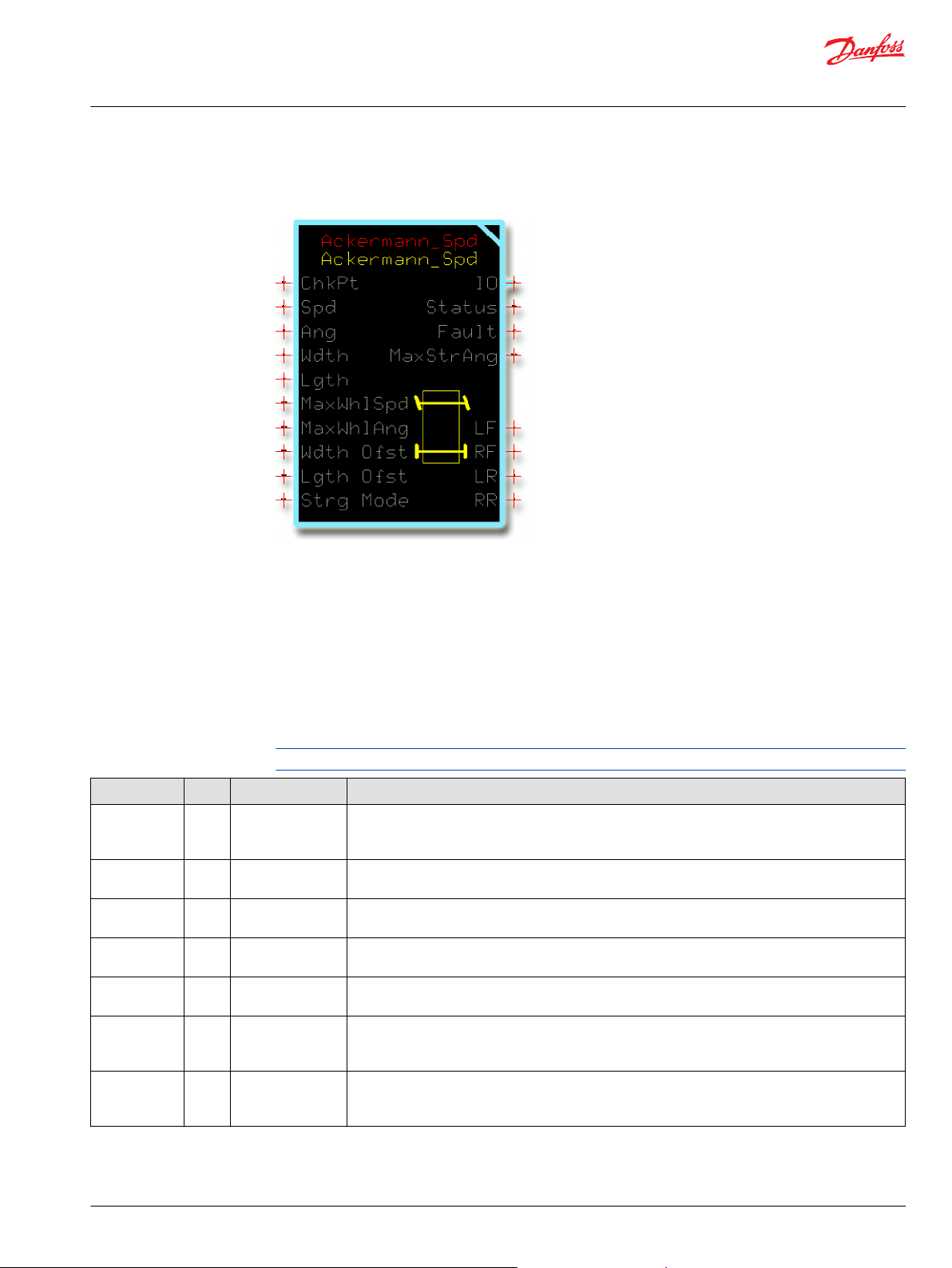
User Manual
PLUS+1® Compliant Function Block Library—Control Function Blocks
Ackermann_Spd Function Block
Use the Ackermann_Spd function block to calculate the wheel speeds for a given average steering
command input and vehicle speed command input.
You can use this function block to calculate wheel speeds for vehicles with:
Two-wheel front steering.
•
Two-wheel rear steering.
•
Four-wheel coordinated steering.
•
Four-wheel crab steering.
•
Inputs
The inputs to the Ackerman_Spd function block are described.
Use only the data types specified in this table. Other data types cause compiler errors.
Item Type Range Description
ChkPt BOOL ——
Spd S16 -20000–20000
Ang S16 -9000–9000
Wdth U16 200–10000
Lgth U16 800–20000
MaxWhlSpd U16 0–20000
MaxWhlAng U16 0–9000
True—include the function block’s built-in Advanced Checkpoint with Namespace
False—exclude the function block’s built-in Advanced Checkpoint with Namespace components
from the compiled LHX download file.
Requested vehicle speed.
1000 = 1000 mm/s
Requested steering angle.
1000 = 10.00°
Width of the vehicle’s wheelbase.
1000 = 1000 mm
Length of vehicle's wheelbase.
1 = 1 mm
Maximum allowed wheel speed in both a positive and a negative direction. Once one wheel reaches
the MaxWhlSpd, the wheel speeds of the other wheels stop increasing.
1000 = 1000 mm/s
The maximum allowed wheel steering angle in both a positive and a negative direction. Once one
wheel reaches the MaxWhlAng, the wheel angles of the other wheels stop increasing.
1000 = 10.00º
©
Danfoss | January 2019 11062085 | AQ284462219091en-000101 | 51
Page 52
User Manual
PLUS+1® Compliant Function Block Library—Control Function Blocks
Ackermann_Spd Function Block
Item Type Range Description
Wdth Ofst S16 -10000–10000 Width offset for the center of rotation when steering.
A positive Wdth Ofst value shifts the center of rotation when steering to the right of the vehicle.
•
A negative Wdth Ofst value shifts the center of rotation when steering to the left of the vehicle.
•
Use the Wdth Ofst to shift your vehicle’s center of rotation when steering if:
You attach an implement to the left or right side of your vehicle.
•
Your vehicle’s wheelbase does not determine the center of rotation when steering.
•
If your vehicle’s wheelbase determines the center of rotation when steering, set the Wdth Ofst value to
0.
1000 = 1000 mm
Lgth Ofst S16 -10000–10000
Strg Mode U8 1–4 Vehicle steering mode:
Length offset for the center of rotation when steering.
A positive Lgth Ofst value shifts the center of rotation when steering toward the front of the vehicle.
•
A negative Lgth Ofst value shifts the center of rotation when steering toward the rear of the vehicle.
•
Use the Lgth Ofst to shift your vehicle’s center of rotation when steering if:
You attach an implement to the front or rear of your vehicle.
•
Your vehicle’s wheelbase does not determine the center of rotation when steering.
•
If your vehicle’s wheelbase determines the center of rotation when steering, set the Wdth Ofst value to
0.
1000 = 1000 mm
1 = Two-wheel front-steering.
•
2 = Two-wheel rear-steering.
•
3 = Four-wheel coordinated-steering.
•
4 = Four-wheel crab-steering.
•
Outputs
The outputs of the Ackermann_Spd function block are described.
Item Type Range Description
IO Bus —— Outputs a bus with all of the function block's input and output signals.
This bus provides a convenient way to distribute this function block's signals to your application.
Status U16 —— Reports the status of the function block.
This output follows the standard bitwise scheme described in the Status Logic topic.
Fault U16 —— Reports the faults of the function block.
This output follows the standard bitwise scheme described in the Status Logic topic.
MaxStrgAng U16 0–9000 The maximum effective Ang input in both a positive and a negative direction.
Any Ang inputs above this value cause no change increase in wheel angles.
The function block calculates this output based on maximum allowed wheel angles and vehicle
geometry.
1000 = 10.00º
LF S16 -20000–20000 Calculated wheel speed for the left-front wheel.
1000 = 1000 mm/s
RF S16 -20000–20000 Calculated wheel speed for the right-front wheel.
1000 = 1000 mm/s
LR S16 -20000–20000 Calculated wheel speed for the left-rear wheel.
1000 = 1000 mm/s
RR S16 -20000–20000 Calculated wheel speed for the right-rear wheel.
1000 = 1000 mm/s
52 | © Danfoss | January 2019 11062085 | AQ284462219091en-000101
Page 53
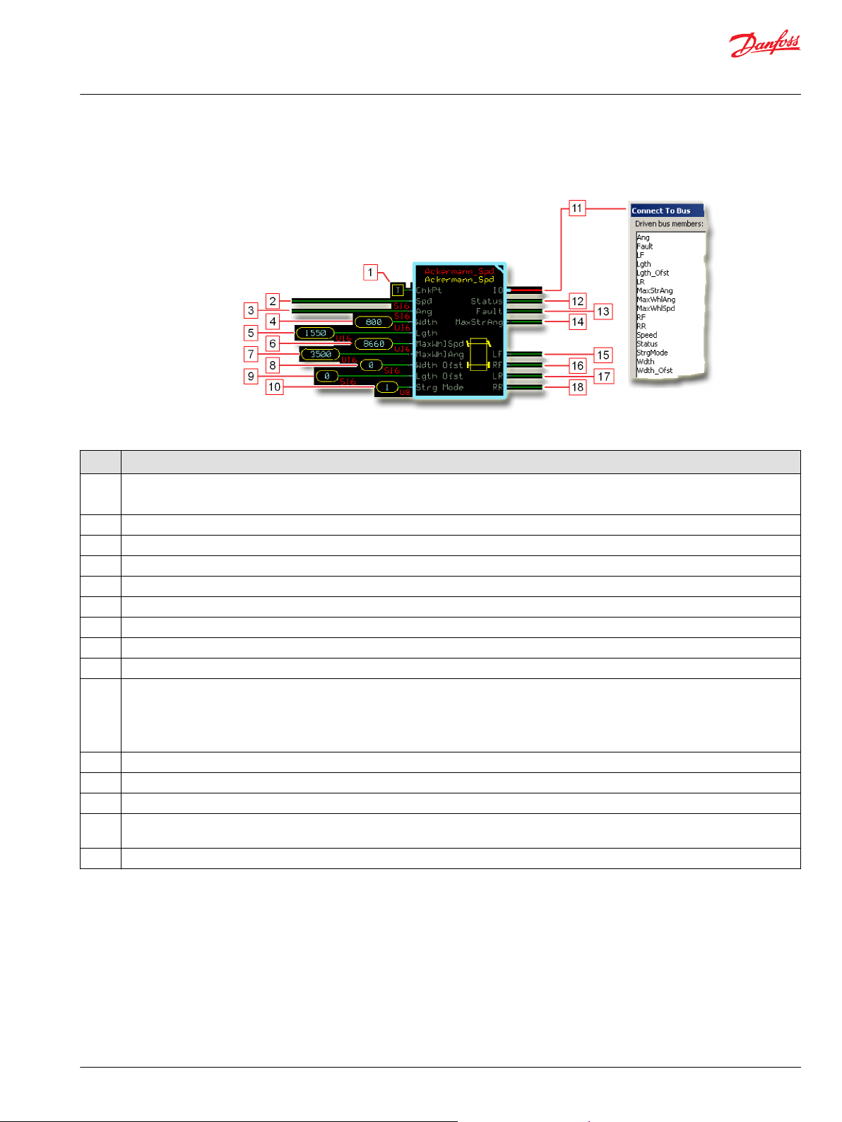
User Manual
PLUS+1® Compliant Function Block Library—Control Function Blocks
Ackermann_Spd Function Block
Function Block Connections
Connections you can make with the function block are described.
Function Block Connections
Description
Item
1.
2. Requested speed.
3. Requested steering angle.
4. Width of the vehicle’s wheelbase.
5. Length of the vehicle‘s wheelbase.
6. Maximum allowed wheel speed in both a positive and a negative direction.
7. The maximum allowed wheel angle in both a positive and a negative direction.
8. Width offset for the center of rotation when steering.
9. Length offset for the center of rotation when steering.
10.
11. Outputs a bus with all of the function block's input and output signals.
12. Reports the status of the function block.
13. Reports the faults of the function block.
14. The maximum effective Ang input in both a positive and a negative direction. Ang inputs above this value cause no further change in wheel
15.
True—include the function block’s built-in Advanced Checkpoint with Namespace in the compiled LHX download file.
•
False—exclude the function block’s built-in Advanced Checkpoint with Namespace components from the compiled LHX download file.
•
1 = Two-wheel front-steering mode.
•
2 = Two-wheel rear-steering mode.
•
3 = Four-wheel coordinated-steering mode.
•
4 = Four-wheel crab-steering mode.
•
angles.
Outputs a bus with calculated LF, RF, LR, and RR wheel speed signals.
©
Danfoss | January 2019 11062085 | AQ284462219091en-000101 | 53
Page 54
User Manual
PLUS+1® Compliant Function Block Library—Control Function Blocks
Ackermann_Spd Function Block
Status and Fault Logic
Use status and fault codes to determine proper program operation.
Status Logic
This topic describes how status logic is indicated for the function block.
Condition Hex
Invalid setup. 0x8008 1000
*
Bit 16 set to 1 identifies a standard Danfoss status or fault code.
Condition Hex
Input value is too low. 0x8001 0001
Input value is too high. 0x8002 0010
*
Bit 16 set to 1 identifies a standard Danfoss status or fault code.
*
Binary Cause Response Correction
Wdth, Lgth, MaxWhlSpd,
MaxWhlAng, Wdth Ofst, or
Lgth Ofst value is out of
range.
Output values based on the
out-of-range value clamped
at either its minimum or
maximum value.
Fault Logic
This topic describes how fault logic is indicated for the function block.
*
Binary Cause Response Correction
Ang value is less than -9000.
Spd value is less than -20000. Return the Spd input to within
Strg Mode value is less than 1. Select a Strg Mode input of 1, 2,
Ang value is greater than 9000. Return the Ang input to within
Spd value is greater than 20000. Return the Spd input to within
Strg Mode value is greater than
4.
LF, RF, LR, and RR outputs
•
hold at 0.
MaxStrgAng output holds at
•
its last valid value.
Return the out-of-range value to
within its correct range.
Return the Ang input to within
its -9000 to 9000 range.
its -20000 to 20000 range.
3, or 4.
its -9000 to 9000 range.
its -20000 to 20000 range..
Select a Strg Mode input of 1, 2,
3, or 4.
54 | © Danfoss | January 2019 11062085 | AQ284462219091en-000101
Page 55

User Manual
PLUS+1® Compliant Function Block Library—Control Function Blocks
Ackermann_Spd Function Block
Steering Modes
Available steering modes are illustrated.
Two-Wheel Front Steering Mode
Two-Wheel Rear Steering Mode
©
Danfoss | January 2019 11062085 | AQ284462219091en-000101 | 55
Page 56
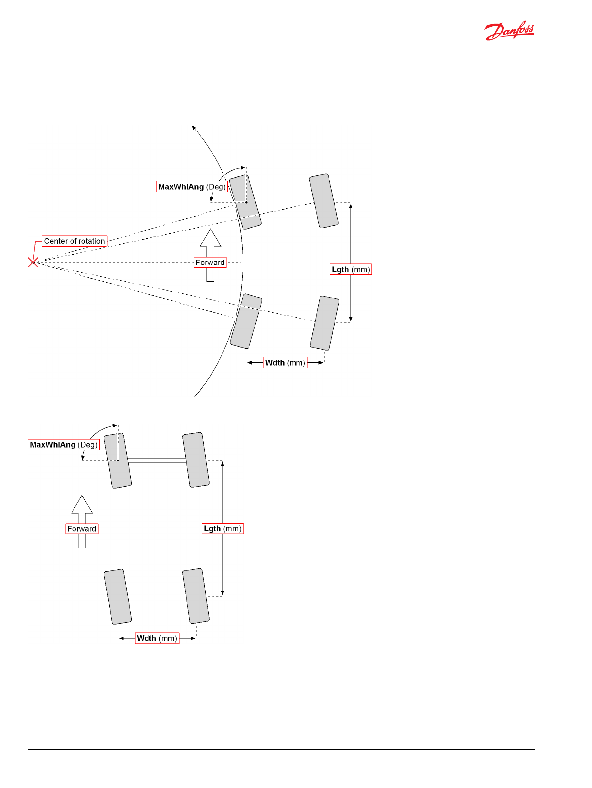
User Manual
PLUS+1® Compliant Function Block Library—Control Function Blocks
Ackermann_Spd Function Block
Four-Wheel Coordinated Steering Mode
Four-Wheel Crab Steering Mode
Identical Function Blocks Need Different Namespace Values to Successfully Compile
If you use the same function block more than once in an application, you must change each function
block’s namespace value to avoid compiler errors.
All function blocks contain Advanced Checkpoint with Namespace components that enable the PLUS+1
Service Tool to read block input and output values.
®
56 | © Danfoss | January 2019 11062085 | AQ284462219091en-000101
Page 57

User Manual
PLUS+1® Compliant Function Block Library—Control Function Blocks
Ackermann_Spd Function Block
Some function blocks contain non-volatile memory components that store function block operating
parameters.
Both these components use memory names (“aliases”) to allocate memory. Identical memory names
cause compiler errors.
The namespace value adds a unique prefix to each component name to avoid errors. Keep each
namespace value short to save controller memory.
Change Namespace Value
To successfully compile your application, change the namespace value for function blocks that are used
more than once in an application.
1. In the PLUS+1® GUIDE menu bar, click the Query/Change button.
2. Click on the function block whose namespace you want to set to a unique value.
The Edit Page window opens.
3. In the Edit Page window, enter a meaningful Namespace value.
Namespace values are case-sensitive.
•
To save controller memory, use a short namespace value.
•
4. Press Enter.
5. Repeat these steps to enter unique namespace values for other identical function blocks.
©
Danfoss | January 2019 11062085 | AQ284462219091en-000101 | 57
Page 58

User Manual
PLUS+1® Compliant Function Block Library—Control Function Blocks
Ackermann_Spd Function Block
IEC 61508-3 Annex D Supplemental Information
The following table provides IEC 61508-3 Annex D supplemental information.
Item
Function block name Ackermann_Spd.
Function block version 4.0.1
Function block development
environment
Compatible hardware
Function block developed in
compliance with
Competence required of
function block integrator
Contacting Danfoss
Description
PLUS+1® GUIDE version 8.1 and later.
Verified in the PLUS+1® GUIDE compile process.
When the PLUS+1® GUIDE compiler finds a function block that is incompatible with hardware, it aborts the compile
process and logs an error message. The error message gives the location of the function block and states “Error 80:
component not supported in hwd.”
Danfoss Software Product Development Process (PDP), which includes ISO 9001 and IEC 61508-3 standards.
The knowledge, competence, and training required to:
Understand this manual.
•
Use the PLUS+1® GUIDE program to develop a machine control application.
•
Follow quality software practices to develop a machine control application.
•
https://www.danfoss.com/en/products/software/dps/plus1-software-services-support-and-training/plus1-support-andservices
58 | © Danfoss | January 2019 11062085 | AQ284462219091en-000101
Page 59

User Manual
PLUS+1® Compliant Function Block Library—Control Function Blocks
Ackermann_Strg Function Block
Use the Ackermann_Strg function block to calculate the wheel angles for a given average steering
command input.
You can use this function block to calculate wheel angles for vehicles with:
Two-wheel front steering.
•
Two-wheel rear steering.
•
Four-wheel coordinated steering.
•
Four-wheel crab steering.
•
Inputs
The inputs to the Ackerman_Strg function block are described.
Use only the data types specified in this table. Other data types cause compiler errors.
Item Type Range Description
ChkPt BOOL ——
Spd S16 -20000–20000
Ang S16 -9000–9000
Wdth U16 200–10000
Lgth U16 800–20000
MaxWhlSpd U16 0–20000
MaxWhlAng U16 0–9000
True—include the function block’s built-in Advanced Checkpoint with Namespace
False—exclude the function block’s built-in Advanced Checkpoint with Namespace components
from the compiled LHX download file.
Requested vehicle speed.
1000 = 1000 mm/s
Requested steering angle.
1000 = 10.00°
Width of the vehicle’s wheelbase.
1000 = 1000 mm
Length of vehicle's wheelbase.
1 = 1 mm
Maximum allowed wheel speed in both a positive and a negative direction. Once one wheel reaches
the MaxWhlSpd, the wheel speeds of the other wheels stop increasing.
1000 = 1000 mm/s
The maximum allowed wheel steering angle in both a positive and a negative direction. Once one
wheel reaches the MaxWhlAng, the wheel angles of the other wheels stop increasing.
1000 = 10.00º
©
Danfoss | January 2019 11062085 | AQ284462219091en-000101 | 59
Page 60

User Manual
PLUS+1® Compliant Function Block Library—Control Function Blocks
Ackermann_Strg Function Block
Item Type Range Description
Wdth Ofst S16 -10000–10000 Width offset for the center of rotation when steering.
A positive Wdth Ofst value shifts the center of rotation when steering to the right of the vehicle.
•
A negative Wdth Ofst value shifts the center of rotation when steering to the left of the vehicle.
•
Use the Wdth Ofst to shift your vehicle’s center of rotation when steering if:
You attach an implement to the left or right side of your vehicle.
•
Your vehicle’s wheelbase does not determine the center of rotation when steering.
•
If your vehicle’s wheelbase determines the center of rotation when steering, set the Wdth Ofst value to
0.
1000 = 1000 mm
Lgth Ofst S16 -10000–10000
Strg Mode U8 1–4 Vehicle steering mode:
Length offset for the center of rotation when steering.
A positive Lgth Ofst value shifts the center of rotation when steering toward the front of the vehicle.
•
A negative Lgth Ofst value shifts the center of rotation when steering toward the rear of the vehicle.
•
Use the Lgth Ofst to shift your vehicle’s center of rotation when steering if:
You attach an implement to the front or rear of your vehicle.
•
Your vehicle’s wheelbase does not determine the center of rotation when steering.
•
If your vehicle’s wheelbase determines the center of rotation when steering, set the Wdth Ofst value to
0.
1000 = 1000 mm
1 = Two-wheel front-steering.
•
2 = Two-wheel rear-steering.
•
3 = Four-wheel coordinated-steering.
•
4 = Four-wheel crab-steering.
•
Outputs
The outputs of the Ackermann_Strg function block are described.
Item Type Range Description
IO Bus —— Outputs a bus with all of the function block's input and output signals.
This bus provides a convenient way to distribute this function block's signals to your application.
Status U16 —— Reports the status of the function block.
This output follows the standard bitwise scheme described in the Status Logic topic.
Fault U16 —— Reports the faults of the function block.
This output follows the standard bitwise scheme described in the Status Logic topic.
MaxStrgAng U16 0–9000 The maximum effective Ang input in both a positive and a negative direction.
Any Ang inputs above this value cause no change increase in wheel angles.
The function block calculates this output based on maximum allowed wheel angles and vehicle
geometry.
1000 = 10.00º
LF S16 -9000–9000 Calculated wheel angle for the left-front wheel.
1000 = 10.00º
RF S16 -9000–9000 Calculated wheel angle for the right-front wheel.
1000 = 10.00º
LR S16 -9000–9000 Calculated wheel angle for the left-rear wheel.
1000 = 10.00º
RR S16 -9000–9000 Calculated wheel angle for the right-rear wheel.
1000 = 10.00º
60 | © Danfoss | January 2019 11062085 | AQ284462219091en-000101
Page 61

User Manual
PLUS+1® Compliant Function Block Library—Control Function Blocks
Ackermann_Strg Function Block
Function Block Connections
Connections you can make with the function block are described.
Description
Item
1.
2. Requested steering angle.
3. Width of the vehicle’s wheelbase.
4. Length of the vehicle‘s wheelbase.
5. The maximum allowed wheel angle in both a positive and a negative direction.
6. Width offset for the center of rotation when steering.
7. Length offset for the center of rotation when steering.
8.
9. Outputs a bus with all of the function block's input and output signals.
10. Reports the status of the function block.
11. Reports the faults of the function block.
12. The maximum effective Ang input in both a positive and a negative direction. Ang inputs above this value cause no further change in wheel
13.
14.
15.
16.
True—include the function block’s built-in Advanced Checkpoint with Namespace in the compiled LHX download file.
•
False—exclude the function block’s built-in Advanced Checkpoint with Namespace components from the compiled LHX download file.
•
1 = Two-wheel front-steering mode.
•
2 = Two-wheel rear-steering mode.
•
3 = Four-wheel coordinated-steering mode.
•
4 = Four-wheel crab-steering mode.
•
angles.
Calculated angle for the left-front wheel.
Calculated angle for the right-front wheel.
Calculated angle for the left-rear wheel.
Calculated angle for the right-rear wheel.
©
Danfoss | January 2019 11062085 | AQ284462219091en-000101 | 61
Page 62

User Manual
PLUS+1® Compliant Function Block Library—Control Function Blocks
Ackermann_Strg Function Block
Status and Fault Logic
Use status and fault codes to determine proper program operation.
Status Logic
This topic describes how status logic is indicated for the function block.
Condition Hex
Invalid setup. 0x8008 1000
*
Bit 16 set to 1 identifies a standard Danfoss status or fault code.
Condition Hex
Input value is too low. 0x8001 0001
Input value is too high. 0x8002 0010
*
Bit 16 set to 1 identifies a standard Danfoss status or fault code.
*
Binary Cause Response Correction
Wdth, Lgth, MaxWhlAng,
Wdth Ofst, or Lgth Ofst
value is out of range.
Output values based on the
out-of-range value clamped
at either its minimum or
maximum value.
Fault Logic
This topic describes how fault logic is indicated for the function block.
*
Binary Cause Response Correction
Ang value is less than -9000.
Strg Mode value is less than 1. Select a outputs hold their
LF, RF, LR, RR and MaxStrgAng
outputs hold their previous valid
Ang value is greater than 9000. Return the Ang input to within
Strg Mode value is greater than
4.
value.
Return the out-of-range value to
within its correct range.
Return the Ang input to within
its -9000 to 9000 range.
previous valid value.Strg Mode
input of 1, 2, 3, or 4.
its -9000 to 9000 range.
Select a Strg Mode input of 1, 2,
3, or 4.
62 | © Danfoss | January 2019 11062085 | AQ284462219091en-000101
Page 63

User Manual
PLUS+1® Compliant Function Block Library—Control Function Blocks
Ackermann_Strg Function Block
Steering Modes
Available steering modes are illustrated.
Two-Wheel Front Steering Mode
Two-Wheel Rear Steering Mode
©
Danfoss | January 2019 11062085 | AQ284462219091en-000101 | 63
Page 64

User Manual
PLUS+1® Compliant Function Block Library—Control Function Blocks
Ackermann_Strg Function Block
Four-Wheel Coordinated Steering Mode
Four-Wheel Crab Steering Mode
Identical Function Blocks Need Different Namespace Values to Successfully Compile
If you use the same function block more than once in an application, you must change each function
block’s namespace value to avoid compiler errors.
All function blocks contain Advanced Checkpoint with Namespace components that enable the PLUS+1
Service Tool to read block input and output values.
®
64 | © Danfoss | January 2019 11062085 | AQ284462219091en-000101
Page 65
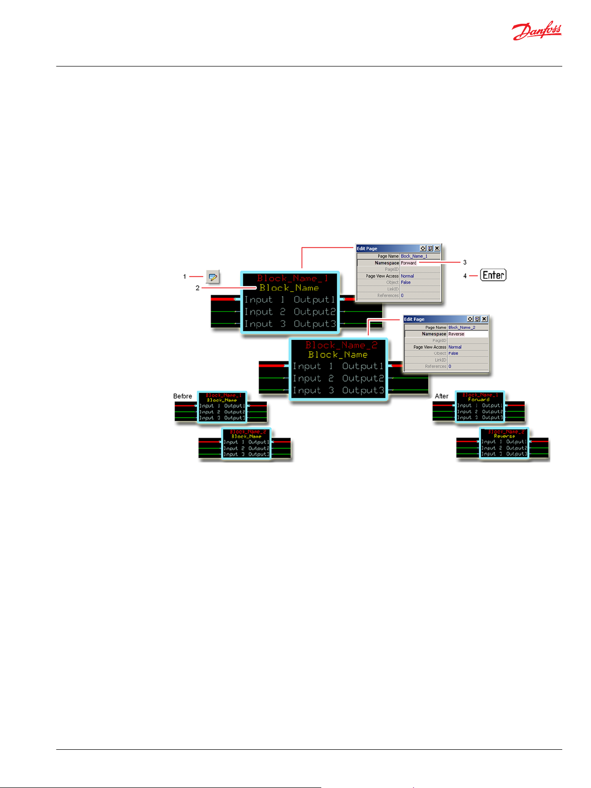
User Manual
PLUS+1® Compliant Function Block Library—Control Function Blocks
Ackermann_Strg Function Block
Some function blocks contain non-volatile memory components that store function block operating
parameters.
Both these components use memory names (“aliases”) to allocate memory. Identical memory names
cause compiler errors.
The namespace value adds a unique prefix to each component name to avoid errors. Keep each
namespace value short to save controller memory.
Change Namespace Value
To successfully compile your application, change the namespace value for function blocks that are used
more than once in an application.
1. In the PLUS+1® GUIDE menu bar, click the Query/Change button.
2. Click on the function block whose namespace you want to set to a unique value.
The Edit Page window opens.
3. In the Edit Page window, enter a meaningful Namespace value.
Namespace values are case-sensitive.
•
To save controller memory, use a short namespace value.
•
4. Press Enter.
5. Repeat these steps to enter unique namespace values for other identical function blocks.
©
Danfoss | January 2019 11062085 | AQ284462219091en-000101 | 65
Page 66

User Manual
PLUS+1® Compliant Function Block Library—Control Function Blocks
Ackermann_Strg Function Block
IEC 61508-3 Annex D Supplemental Information
The following table provides IEC 61508-3 Annex D supplemental information.
Item
Function block name Ackermann_Strg.
Function block version 4.0.
Function block development
environment
Compatible hardware
Function block developed in
compliance with
Competence required of
function block integrator
Contacting Danfoss
Description
PLUS+1® GUIDE version 8.1 and later.
Verified in the PLUS+1® GUIDE compile process.
When the PLUS+1® GUIDE compiler finds a function block that is incompatible with hardware, it aborts the compile
process and logs an error message. The error message gives the location of the function block and states “Error 80:
component not supported in hwd.”
Danfoss Software Product Development Process (PDP), which includes ISO 9001 and IEC 61508-3 standards.
The knowledge, competence, and training required to:
Understand this manual.
•
Use the PLUS+1® GUIDE program to develop a machine control application.
•
Follow quality software practices to develop a machine control application.
•
https://www.danfoss.com/en/products/software/dps/plus1-software-services-support-and-training/plus1-support-andservices
66 | © Danfoss | January 2019 11062085 | AQ284462219091en-000101
Page 67
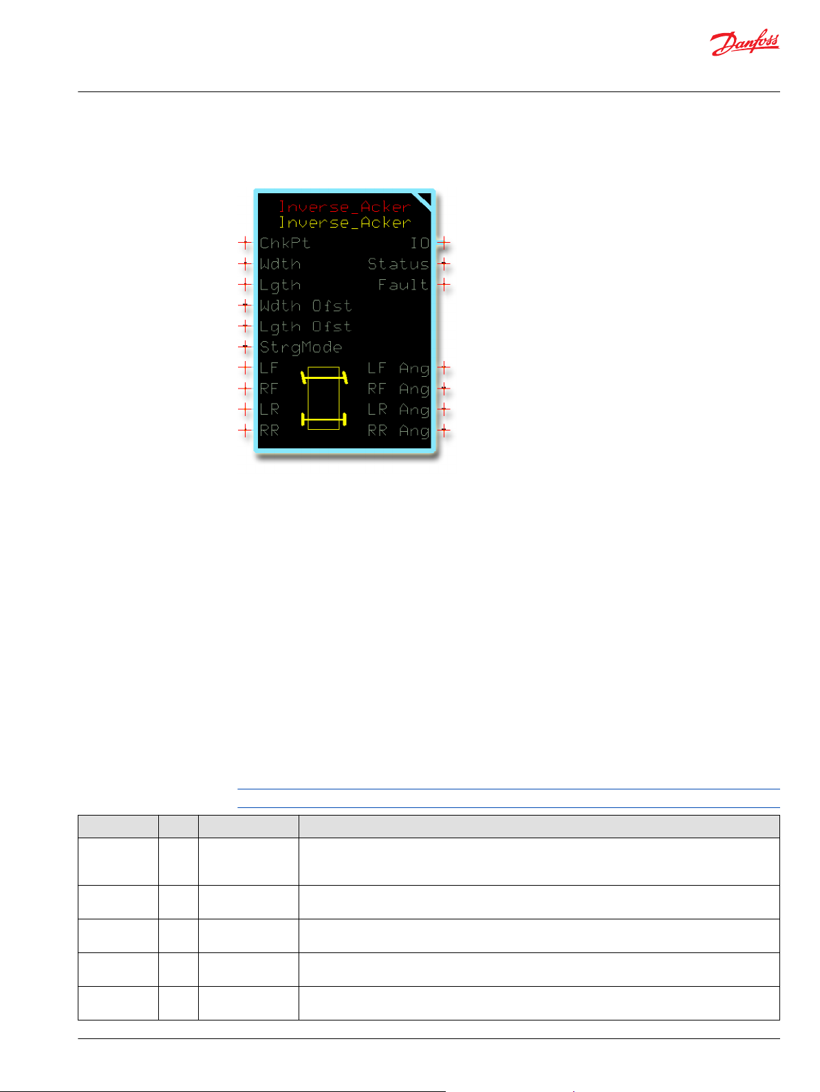
User Manual
PLUS+1® Compliant Function Block Library—Control Function Blocks
Inverse_Acker Function Block
The Inverse_Acker function block uses measured wheel angles and steering mode to determine the
original steering angle command.
Steer-by-wire systems typically do not save the last known steering angle when the system powers off.
Smaller steering systems may initialize the steering to zero degrees on startup to align the wheels with
the steering. This can be a potentially dangerous safety situation for anyone near the wheels during
alignment.
Use the Inverse_Acker block to preset the steering system based on the angle of the tires to minimize
wheel re-alignment motion.
You can use this function block to:
Calculate wheel angles for vehicles with independently actuated steering applications.
•
Calculate wheel angles for vehicles with steer-by-wire applications that do not store the last steer
•
angle in non-volatile memory.
Determine the commanded steering angle before the vehicle shut down.
•
Detect if a wheel lost alignment while the vehicle was shut down to allow for a warning before wheel
•
realignment occurs.
Inputs
The inputs to the function block are described.
Use only the data types specified in this table. Other data types cause compiler errors.
Item Type Range Description
ChkPt BOOL ——
Spd S16 -20000–20000
Ang S16 -9000–9000
Wdth U16 200–10000
Lgth U16 800–20000
True—include the function block’s built-in Advanced Checkpoint with Namespace
False—exclude the function block’s built-in Advanced Checkpoint with Namespace components
from the compiled LHX download file.
Requested vehicle speed.
1000 = 1000 mm/s
Requested steering angle.
1000 = 10.00°
Width of the vehicle’s wheelbase.
1000 = 1000 mm
Length of vehicle's wheelbase.
1 = 1 mm
©
Danfoss | January 2019 11062085 | AQ284462219091en-000101 | 67
Page 68
User Manual
PLUS+1® Compliant Function Block Library—Control Function Blocks
Inverse_Acker Function Block
Item Type Range Description
MaxWhlSpd U16 0–20000
MaxWhlAng U16 0–9000
Wdth Ofst S16 -10000–10000 Width offset for the center of rotation when steering.
Lgth Ofst S16 -10000–10000
Strg Mode U8 1–4 Vehicle steering mode:
LF S16 -9000–9000
RF S16 -9000–9000
LR S16 -9000–9000
RR S16 -9000–9000
Maximum allowed wheel speed in both a positive and a negative direction. Once one wheel reaches
the MaxWhlSpd, the wheel speeds of the other wheels stop increasing.
1000 = 1000 mm/s
The maximum allowed wheel steering angle in both a positive and a negative direction. Once one
wheel reaches the MaxWhlAng, the wheel angles of the other wheels stop increasing.
1000 = 10.00º
A positive Wdth Ofst value shifts the center of rotation when steering to the right of the vehicle.
•
A negative Wdth Ofst value shifts the center of rotation when steering to the left of the vehicle.
•
Use the Wdth Ofst to shift your vehicle’s center of rotation when steering if:
You attach an implement to the left or right side of your vehicle.
•
Your vehicle’s wheelbase does not determine the center of rotation when steering.
•
If your vehicle’s wheelbase determines the center of rotation when steering, set the Wdth Ofst value to
0.
1000 = 1000 mm
Length offset for the center of rotation when steering.
A positive Lgth Ofst value shifts the center of rotation when steering toward the front of the vehicle.
•
A negative Lgth Ofst value shifts the center of rotation when steering toward the rear of the vehicle.
•
Use the Lgth Ofst to shift your vehicle’s center of rotation when steering if:
You attach an implement to the front or rear of your vehicle.
•
Your vehicle’s wheelbase does not determine the center of rotation when steering.
•
If your vehicle’s wheelbase determines the center of rotation when steering, set the Wdth Ofst value to
0.
1000 = 1000 mm
1 = Two-wheel front-steering.
•
2 = Two-wheel rear-steering.
•
3 = Four-wheel coordinated-steering.
•
4 = Four-wheel crab-steering.
•
Feedback angle from the left-front wheel.
1000 = 10.00º.
Feedback angle from the right-front wheel.
1000 = 10.00º.
Feedback angle from the left-rear wheel.
1000 = 10.00º.
Feedback angle from the right-rear wheel.
1000 = 10.00º.
Outputs
The outputs of the Inverse_Ackermann function block are described.
Item Type Range Description
IO Bus —— Outputs a bus with all of the function block's input and output signals.
This bus provides a convenient way to distribute this function block's signals to your application.
Status U16 —— Reports the status of the function block.
This output follows the standard bitwise scheme described in the Status Logic topic.
Fault U16 —— Reports the faults of the function block.
This output follows the standard bitwise scheme described in the Status Logic topic.
LF Ang S16 -9000–9000 Estimated vehicle steering input command based on the feedback angle from the left-front wheel.
1000 = 10.00º
RF Ang S16 -9000–9000 Estimated vehicle steering input command based on the feedback angle from the right-front wheel.
1000 = 10.00º
68 | © Danfoss | January 2019 11062085 | AQ284462219091en-000101
Page 69
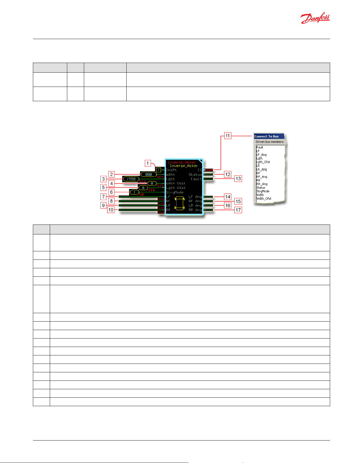
User Manual
PLUS+1® Compliant Function Block Library—Control Function Blocks
Inverse_Acker Function Block
Item Type Range Description
LR Ang S16 -9000–9000 Estimated vehicle steering input command based on the feedback angle from the left-rear wheel.
1000 = 10.00º
RR Ang S16 -9000–9000 Estimated vehicle steering input command based on the feedback angle from the left-rear wheel.
1000 = 10.00º
Function Block Connections
Connections you can make with the function block are described.
Description
Item
1.
2. Width of the vehicle’s wheelbase.
3. Length of the vehicle‘s wheelbase.
4. Width offset for the center of rotation when steering.
5. Length offset for the center of rotation when steering.
6.
7.
8.
9.
10.
11. Outputs a bus with all of the function block's input and output signals.
12. Reports the status of the function block.
13. Reports the faults of the function block.
14.
15.
16.
17.
True—include the function block’s built-in Advanced Checkpoint with Namespace in the compiled LHX download file.
•
False—exclude the function block’s built-in Advanced Checkpoint with Namespace components from the compiled LHX download file.
•
1 = Two-wheel front-steering mode.
•
2 = Two-wheel rear-steering mode.
•
3 = Four-wheel coordinated-steering mode.
•
4 = Four-wheel crab-steering mode.
•
Feedback angle from the left-front wheel.
Feedback angle from the right-front wheel.
Feedback angle from the left-rear wheel.
Feedback angle from the right-rear wheel.
Estimated vehicle steering input command based on the feedback angle from the left-front wheel.
Estimated vehicle steering input command based on the feedback angle from the right-front wheel.
Estimated vehicle steering input command based on the feedback angle from the left-rear wheel.
Estimated vehicle steering input command based on the feedback angle from the right-rear wheel.
©
Danfoss | January 2019 11062085 | AQ284462219091en-000101 | 69
Page 70

User Manual
PLUS+1® Compliant Function Block Library—Control Function Blocks
Inverse_Acker Function Block
How the Inverse_Acker Function Block Works to Restore Lost Ang Inputs
The Ang input to an Ackermann or Ackermann_Strg function block can be used to control wheel
angles.
Depending on an application’s configuration, the Ang input may be lost on power down. Loss of the Ang
input can cause unpredictable and possibly unsafe wheel movements on power up. The following figure
shows how the Inverse_Acker function block can restore the lost Ang input on power up. The logic
shown here applies to both Ackermann_Strg and Ackermann function blocks.
Description
Item
1. The Ang value input to the Ackermann_Strg function block requests a steering angle.
2a. The Ackermann_Strg and Inverse_Acker function blocks have identical Wdth and Lgth values.
2b. The Ackermann_Strg and Inverse_Acker function blocks have identical Wdth Ofst and Lgth Ofst values.
2c. The Ackermann_Strg and Inverse_Acker function blocks have identical Wdth and Lgth values.
The Ackermann_Strg function block outputs calculated LF and RF wheel angles that position the vehicle’s wheels. Depending on an
3.
application’s configuration, powering down the application can cause the Ang value that produces these wheel angles to be lost. Loss of the
Ang value can cause unpredictable wheel movements when the application again powers up.
The Inverse_Acker function block’s LF and RF inputs receive wheel angle inputs. On application power up, the Inverse_Acker function block
4.
uses these inputs to calculate the original Ang input (item 1) that produced each wheel angle.
Typically, the LF Ang and RF Ang outputs:
5.
Equal or nearly equal to each other.
•
Equal or nearly equal the original Ang input (item 1) to the Ackermann_Strg function block.
•
6. The application software averages the Inverse_Acker function block’s LF Ang and RF Ang outputs. It then applies the result to the
Ackermann_Strg function block’s Ang input (item 1.). This restores the original Ang value that was lost when the application powered down.
Steering control resumes without unpredictable wheel movement.
70 | © Danfoss | January 2019 11062085 | AQ284462219091en-000101
Page 71
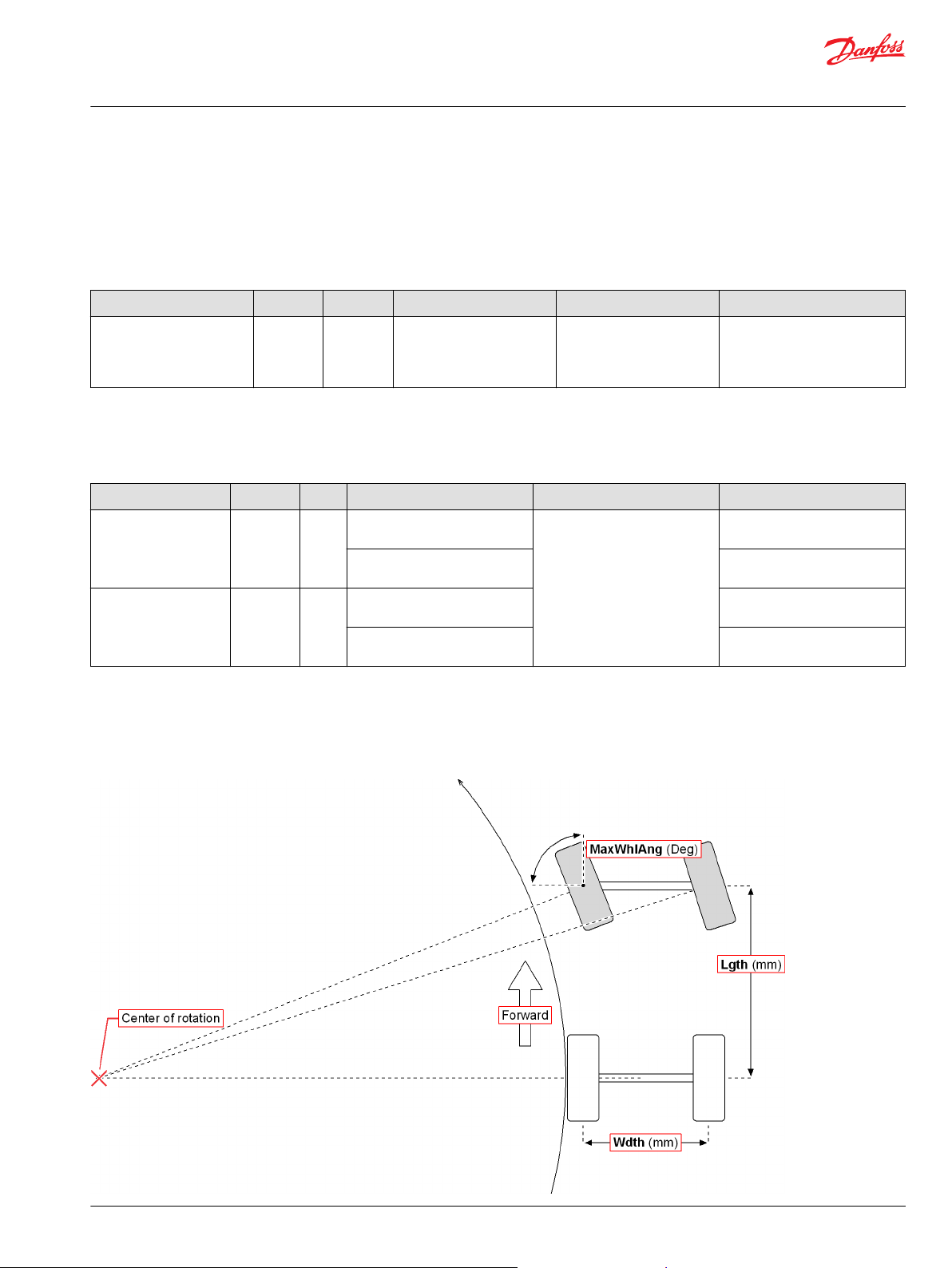
User Manual
PLUS+1® Compliant Function Block Library—Control Function Blocks
Inverse_Acker Function Block
Status and Fault Logic
Use status and fault codes to determine proper program operation.
Status Logic
This topic describes how status logic is indicated for the function block.
Condition Hex
Invalid setup. 0x8008 1000
*
Bit 16 set to 1 identifies a standard Danfoss status or fault code.
Condition Hex
Input value is too low. 0x8001 0001
Input value is too high. 0x8002 0010
*
Bit 16 set to 1 identifies a standard Danfoss status or fault code.
*
Binary Cause Response Correction
Wdth, Lgth, Wdth Ofst, or
Lgth Ofst value is out of
range.
Output values based on the
out-of-range value clamped
at either its minimum or
maximum value.
Fault Logic
This topic describes how fault logic is indicated for the function block.
*
Binary Cause Response Correction
LF, RF, LF, or RR value is less
than -9000.
Strg Mode value is less than 1. Select a Strg Mode input of 1, 2,
LF, RF, LF, or RR value is greater
than 9000.
Strg Mode value is greater than
4.
LF Ang, RF Ang, LR Ang, and RR
Ang outputs hold at their
previous values.
Return the out-of-range value to
within its correct range.
Return the LF, RF, LF, or RR input
to within its -9000 to 9000 range.
3, or 4.
Return the LF, RF, LF, or RR input
to within its -9000 to 9000 range.
Select a Strg Mode input of 1, 2,
3, or 4.
Steering Modes
Two-Wheel Front Steering Mode
Available steering modes are illustrated.
©
Danfoss | January 2019 11062085 | AQ284462219091en-000101 | 71
Page 72
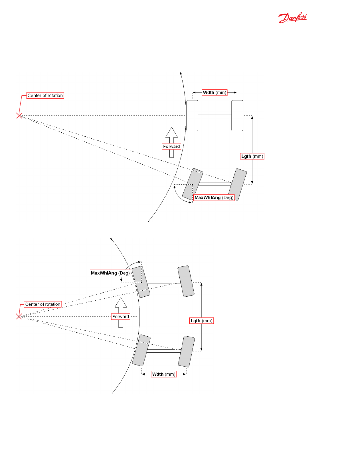
User Manual
PLUS+1® Compliant Function Block Library—Control Function Blocks
Inverse_Acker Function Block
Two-Wheel Rear Steering Mode
Four-Wheel Coordinated Steering Mode
72 | © Danfoss | January 2019 11062085 | AQ284462219091en-000101
Page 73
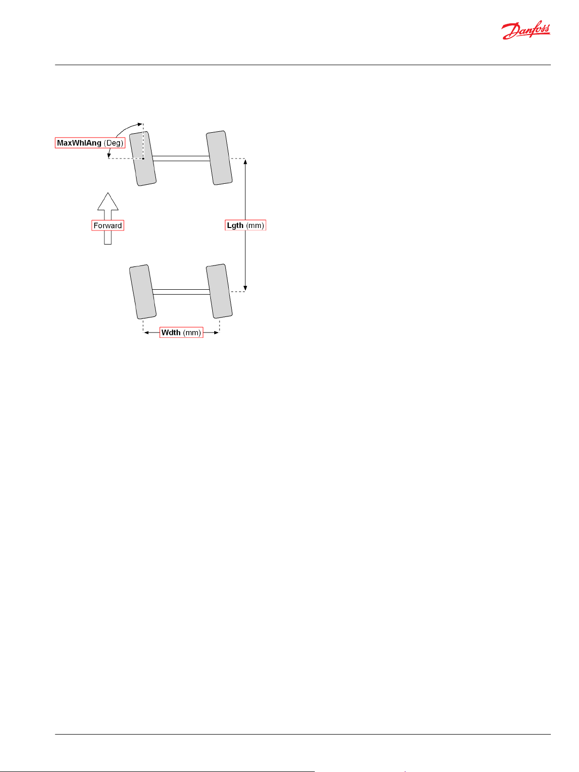
User Manual
PLUS+1® Compliant Function Block Library—Control Function Blocks
Inverse_Acker Function Block
Four-Wheel Crab Steering Mode
Identical Function Blocks Need Different Namespace Values to Successfully Compile
If you use the same function block more than once in an application, you must change each function
block’s namespace value to avoid compiler errors.
All function blocks contain Advanced Checkpoint with Namespace components that enable the PLUS+1
Service Tool to read block input and output values.
Some function blocks contain non-volatile memory components that store function block operating
parameters.
Both these components use memory names (“aliases”) to allocate memory. Identical memory names
cause compiler errors.
The namespace value adds a unique prefix to each component name to avoid errors. Keep each
namespace value short to save controller memory.
®
©
Danfoss | January 2019 11062085 | AQ284462219091en-000101 | 73
Page 74

User Manual
PLUS+1® Compliant Function Block Library—Control Function Blocks
Inverse_Acker Function Block
Change Namespace Value
To successfully compile your application, change the namespace value for function blocks that are used
more than once in an application.
1. In the PLUS+1® GUIDE menu bar, click the Query/Change button.
2. Click on the function block whose namespace you want to set to a unique value.
The Edit Page window opens.
3. In the Edit Page window, enter a meaningful Namespace value.
Namespace values are case-sensitive.
•
To save controller memory, use a short namespace value.
•
4. Press Enter.
5. Repeat these steps to enter unique namespace values for other identical function blocks.
74 | © Danfoss | January 2019 11062085 | AQ284462219091en-000101
Page 75

User Manual
PLUS+1® Compliant Function Block Library—Control Function Blocks
Inverse_Acker Function Block
IEC 61508-3 Annex D Supplemental Information
The following table provides IEC 61508-3 Annex D supplemental information.
Item
Function block name Inverse_Acker.
Function block version 4.0.1
Function block development
environment
Compatible hardware
Function block developed in
compliance with
Competence required of
function block integrator
Contacting Danfoss
Description
PLUS+1® GUIDE version 8.1 and later.
Verified in the PLUS+1® GUIDE compile process.
When the PLUS+1® GUIDE compiler finds a function block that is incompatible with hardware, it aborts the compile
process and logs an error message. The error message gives the location of the function block and states “Error 80:
component not supported in hwd.”
Danfoss Software Product Development Process (PDP), which includes ISO 9001 and IEC 61508-3 standards.
The knowledge, competence, and training required to:
Understand this manual.
•
Use the PLUS+1® GUIDE program to develop a machine control application.
•
Follow quality software practices to develop a machine control application.
•
https://www.danfoss.com/en/products/software/dps/plus1-software-services-support-and-training/plus1-support-andservices
©
Danfoss | January 2019 11062085 | AQ284462219091en-000101 | 75
Page 76

User Manual
PLUS+1® Compliant Function Block Library—Control Function Blocks
Hysteresis Function Block
Use the Hysteresis function block to remove hysteresis from an input by adding an offset when the input
increases and subtracting an offset when the input decreases.
When the input is constant the offset ramps to zero, eventually resulting in an output that equals the
input.
You can use this function block to:
Compensate for mechanical lags.
•
Improve an application’s response to hysteresis step-changes in an input signal. In this use, the signal
•
input to this function block should not command frequent direction changes. In an application,
sudden changes in this function block’s output should be tolerated or desirable.
Inputs
The inputs to the Hysteresis function block are described.
Use only the data types specified in this table. Other data types cause compiler errors.
Item Type Range Description
ChkPt BOOL ——
Ramp U16 0–32767
Hyst U16 0–32767 The hysteresis offset that the function block applies to its Output when its Input changes.
Input U16 0–32767
True—include the function block’s built-in Advanced Checkpoint with Namespace
False—exclude the function block’s built-in Advanced Checkpoint with Namespace components
from the compiled LHX download file.
The function block applies a Hyst offset to its Output to compensate for hysteresis.
The Ramp value sets the time that the function block takes to linearly ramp the Hyst offset to 0. With a
steady Input, this function block’s Output will equal its Input at the end of the Ramp time.
1000 = 1000 ms.
When the function block’s Input:
Increases, the function block adds the Hyst value to its Output.
•
Decreases, the function block subtracts the Hyst value from its Output.
•
The input signal that needs hysteresis compensation.
Outputs
The outputs of the Hysteresis function block are described.
Item Type Range Description
IO Bus —— Outputs a bus with all of the function block's input and output signals.
This bus provides a convenient way to distribute this function block's signals to your application.
Status U16 —— Reports the status of the function block.
This output follows the standard bitwise scheme described in the Status Logic topic.
Fault U16 —— Reports the faults of the function block.
This output follows the standard bitwise scheme described in the Status Logic topic.
Output U16 0–32767 The Input signal after hysteresis compensation.
76 | © Danfoss | January 2019 11062085 | AQ284462219091en-000101
Page 77

User Manual
PLUS+1® Compliant Function Block Library—Control Function Blocks
Hysteresis Function Block
Function Block Connections
Connections you can make with the function block are described.
Function Block Connections
Description
Item
1.
2.
3.
4.
5. Outputs a bus with all of the function block's input and output signals.
6. Reports the status of the function block.
7. Reports the faults of the function block.
8.
True—include the function block’s built-in Advanced Checkpoint with Namespace in the compiled LHX download file.
•
False—exclude the function block’s built-in Advanced Checkpoint with Namespace components from the compiled LHX download file.
•
The function block applies a Hyst offset to its Output to compensate for hysteresis. The Ramp value sets the time that the function block takes
to linearly ramp the Hyst offset to 0.
The hysteresis offset applied to the function block’s Output when its Input changes.
The input signal that needs hysteresis compensation.
The Input signal after hysteresis compensation.
©
Danfoss | January 2019 11062085 | AQ284462219091en-000101 | 77
Page 78

User Manual
PLUS+1® Compliant Function Block Library—Control Function Blocks
Hysteresis Function Block
Function Block Example
Use the following example to understand how configuration changes impact the output of the function
block.
The plot above shows how the Hysteresis function block applies hysteresis compensation when the
value of its Input signal suddenly increases.
Figure Details
Description
Item
1. From 0 ms to 200 ms, an Input of 200 to the function block produces a steady Output of 200.
At 200 ms, the Input to the function block increases by 500, from 200 to 700. From 200 ms on, the Input holds at 700.
2.
3. At 200 ms, the function block applies a Hyst offset of 200 to increase its Output from 700 to 900.
Between 200 ms and 700 ms, the function block applies a Ramp time of 500 ms to ramp down the Hyst offset applied to its Output to 0.
4.
At 700 ms, at the end of the Ramp time, the function block’s Output equals its Input.
5.
78 | © Danfoss | January 2019 11062085 | AQ284462219091en-000101
Page 79

User Manual
PLUS+1® Compliant Function Block Library—Control Function Blocks
Hysteresis Function Block
The plot above shows how the Hysteresis function block applies hysteresis compensation when the
value of its Input signal suddenly decreases.
Figure Details
Description
Item
1. From 0 ms to 200 ms, an Input of 200 to the function block produces a steady Output of 700.
At 200 ms, the Input to the function block decreases by 500, from 700 to 200. From 200 ms on, the Input holds at 200.
2.
3. At 200 ms, the function block applies a Hyst offset of 200 to decrease its Output from 200 to 0.
Between 200 ms and 700 ms, the function block applies a Ramp time of 500 ms to ramp down the Hyst offset applied to its Output to 0.
4.
At 700 ms, at the end of the Ramp time, the function block’s Output equals its Input.
5.
©
Danfoss | January 2019 11062085 | AQ284462219091en-000101 | 79
Page 80
User Manual
PLUS+1® Compliant Function Block Library—Control Function Blocks
Hysteresis Function Block
Status and Fault Logic
Use status and fault codes to determine proper program operation.
Status Logic
This topic describes how status logic is indicated for the function block.
Condition Hex
Invalid setup. 0x8008 1000 Ramp or Hyst parameter is
*
Bit 16 set to 1 identifies a standard Danfoss status or fault code.
Condition Hex
Input value is too high. 0x8002 0010 Input value > 32767. Output = 32767 Return the Input to the valid
*
Bit 16 set to 1 identifies a standard Danfoss status or fault code.
*
Binary Cause Response Correction
Limits the Ramp or Hyst
out-of-range.
value to the defined
maximum.
Fault Logic
This topic describes how fault logic is indicated for the function block.
*
Binary Cause Response Correction
Return the Ramp or Hyst
parameter to the valid range.
range.
Identical Function Blocks Need Different Namespace Values to Successfully Compile
If you use the same function block more than once in an application, you must change each function
block’s namespace value to avoid compiler errors.
All function blocks contain Advanced Checkpoint with Namespace components that enable the PLUS+1
Service Tool to read block input and output values.
Some function blocks contain non-volatile memory components that store function block operating
parameters.
Both these components use memory names (“aliases”) to allocate memory. Identical memory names
cause compiler errors.
The namespace value adds a unique prefix to each component name to avoid errors. Keep each
namespace value short to save controller memory.
®
80 | © Danfoss | January 2019 11062085 | AQ284462219091en-000101
Page 81

User Manual
PLUS+1® Compliant Function Block Library—Control Function Blocks
Hysteresis Function Block
Change Namespace Value
To successfully compile your application, change the namespace value for function blocks that are used
more than once in an application.
1. In the PLUS+1® GUIDE menu bar, click the Query/Change button.
2. Click on the function block whose namespace you want to set to a unique value.
The Edit Page window opens.
3. In the Edit Page window, enter a meaningful Namespace value.
Namespace values are case-sensitive.
•
To save controller memory, use a short namespace value.
•
4. Press Enter.
5. Repeat these steps to enter unique namespace values for other identical function blocks.
©
Danfoss | January 2019 11062085 | AQ284462219091en-000101 | 81
Page 82

User Manual
PLUS+1® Compliant Function Block Library—Control Function Blocks
Hysteresis Function Block
IEC 61508-3 Annex D Supplemental Information
The following table provides IEC 61508-3 Annex D supplemental information.
Item
Function block name Hysteresis.
Function block version 4.0.
Function block development
environment
Compatible hardware
Function block developed in
compliance with
Competence required of
function block integrator
Contacting Danfoss
Description
PLUS+1® GUIDE version 8.1 and later.
Verified in the PLUS+1® GUIDE compile process.
When the PLUS+1® GUIDE compiler finds a function block that is incompatible with hardware, it aborts the compile
process and logs an error message. The error message gives the location of the function block and states “Error 80:
component not supported in hwd.”
Danfoss Software Product Development Process (PDP), which includes ISO 9001 and IEC 61508-3 standards.
The knowledge, competence, and training required to:
Understand this manual.
•
Use the PLUS+1® GUIDE program to develop a machine control application.
•
Follow quality software practices to develop a machine control application.
•
https://www.danfoss.com/en/products/software/dps/plus1-software-services-support-and-training/plus1-support-andservices
82 | © Danfoss | January 2019 11062085 | AQ284462219091en-000101
Page 83
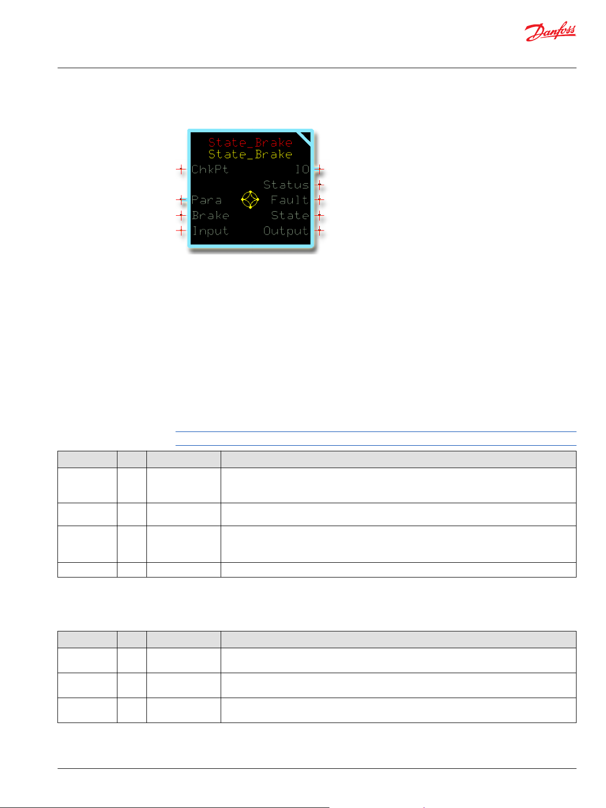
User Manual
PLUS+1® Compliant Function Block Library—Control Function Blocks
State_Brake Function Block
Use the State_Brake function block in applications that need smooth transition signals.
This function block has parameters to smooth:
Acceleration transitions.
•
Coasting transitions.
•
Change of direction transitions.
•
Braking transitions.
•
Deceleration to neutral.
•
Typically, you use this function block in propel applications that require smooth starting and stopping
but need faster ramp rates for other conditions.
Inputs
The inputs to the State _Brake function block are described.
Use only the data types specified in this table. Other data types cause compiler errors.
Item Type Range Description
ChkPt BOOL ——
Para Bus —— Input for acceleration and deceleration parameters that set how this function block’s Output ramps in
Brake BOOL ——
Input S16 -10000–10000
True—include the function block’s built-in Advanced Checkpoint with Namespace
False—exclude the function block’s built-in Advanced Checkpoint with Namespace components
from the compiled LHX download file.
response to changes in its Input.
True—ignore the Input value and apply the Brake parameters to ramp the Output value to 0.
•
False—apply the appropriate acceleration and deceleration parameters to the Output value in
•
response to changes in the Input value.
Command signal to be ramped.
Outputs
The outputs of the State_Brake function block are described.
Item Type Range Description
IO Bus —— Outputs a bus with all of the function block's input and output signals.
This bus provides a convenient way to distribute this function block's signals to your application.
Status U16 —— Reports the status of the function block.
This output follows the standard bitwise scheme described in the Status Logic topic.
Fault U16 —— Reports the faults of the function block.
This output follows the standard bitwise scheme described in the Status Logic topic.
©
Danfoss | January 2019 11062085 | AQ284462219091en-000101 | 83
Page 84
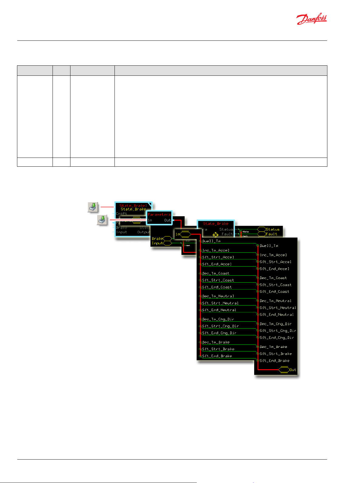
User Manual
PLUS+1® Compliant Function Block Library—Control Function Blocks
State_Brake Function Block
Item Type Range Description
State U8 0–5 Reports the function block’s current state.
0 = Not ramping; the Input equals the Output and the brake is not active.
•
1 = The Input commands a deceleration but not a deceleration to neutral. The function block applies
•
Coast parameters to its Output.
2 = The Input commands deceleration to neutral. The function block applies Neutral parameters to
•
its Output.
3 = The Input commands a change in direction. The function block applies Chg_Dir and Dwell_Tm
•
parameters to its Output.
4 = The boolean Brake input goes true and commands braking to neutral. The function block applies
•
Brake parameters to its Output.
5 = The Input commands forward or reverse acceleration. The function block applies Accel
•
parameters to its Output.
Output S16 -10000–10000 The Input command after ramping.
Parameters
The parameters of the State_Brake function block are described.
The Parameters page provides access to the function block’s parameter (configuration) values.
Typically, you input parameter values from an external page to this function block through its Para input.
84 | © Danfoss | January 2019 11062085 | AQ284462219091en-000101
Page 85
User Manual
PLUS+1® Compliant Function Block Library—Control Function Blocks
State_Brake Function Block
Item Type Range Description
Dwell Tm U16 0–65535 The time that the function block’s Output must remain at 0 when its Input commands a
change in direction.
1000 = 1000 ms
Inc_Tm_Accel U16 0–65535 The time that the function block’s Output takes to go from 0 to 10000 or from 0 to
-10000 when its Input commands 100.00% acceleration.
1000 = 1000 ms
Sft_Strt_Accel U16 0–10000 The non-linear, soft-start portion of the Inc_Tm_Accel ramp as a percentage of this
ramp’s total time.
10000 = 100.00%.
Sft_End_Accel U16 0–10000 The non-linear, soft-end portion of the Inc_Tm_Accel ramp as a percentage of this
ramp’s total time.
10000 = 100.00%.
Dec_Tm_Coast U16 0–65535 The time that the function block’s Output takes to go from 10000 to 1 or from -10000 to
-1 when its Input commands deceleration to 1 or -1.
The Dec_Tm_Coast value applies when the Input commands a deceleration but not
•
a deceleration to neutral.
The Dec_Tm_Neutral value applies when the Input commands a deceleration to
•
neutral.
1000 = 1000 ms
Sft_End_Coast U16 0–10000 The non-linear, soft-end portion of the Dec_Tm_Coast ramp as a percentage of this
ramp’s total time.
10000 = 100.00%.
Sft_Strt_Coast U16 0–10000 The non-linear, soft-start portion of the Dec_Tm_Coast ramp as a percentage of this
ramp’s total time.
10000 = 100.00%.
Dec_Tm_Neutral U16 0–65535 The time that the function block’s Output takes to go from 10000 to 0 or from -10000 to
0 when its Input commands deceleration to neutral.
The Dec_Tm_Coast value applies when the Input commands a deceleration but not
•
a deceleration to neutral.
The Dec_Tm_Neutral value applies when the Input commands a deceleration to
•
neutral.
1000 = 1000 ms
Sft_Strt_Neutral U16 0–10000 The non-linear, soft-start portion of the Dec_Tm_Neutral ramp as a percentage of this
ramp’s total time.
10000 = 100.00%.
Sft_End_Neutral U16 0–10000 The non-linear, soft-end portion of the Dec_Tm_Neutral ramp as a percentage of this
ramp’s total time.
10000 = 100.00%.
Dec_Tm_Chg_Dir U16 0–65535
Sft_Strt_Chg_Dir U16 0–10000 The non-linear, soft-start portion of the Dec_Tm_Chg_Dir ramp as a percentage of this
Sft_End_Chg_Dir U16 0–10000 The non-linear, soft-end portion of the Dec_Tm_Chg_Dir ramp as a percentage of this
Dec_Tm_Brake U16 0–65535
The time that the function block’s Output takes to go from 10000 to 0 or from -10000 to
0 when its Input commands a change in direction.
1000 = 1000 ms
ramp’s total time.
10000 = 100.00%.
ramp’s total time.
10000 = 100.00%.
The time that the function block’s Output takes to go from 10000 to 0 or from -10000 to
0 when its boolean Brake input goes true.
1000 = 1000 ms
©
Danfoss | January 2019 11062085 | AQ284462219091en-000101 | 85
Page 86
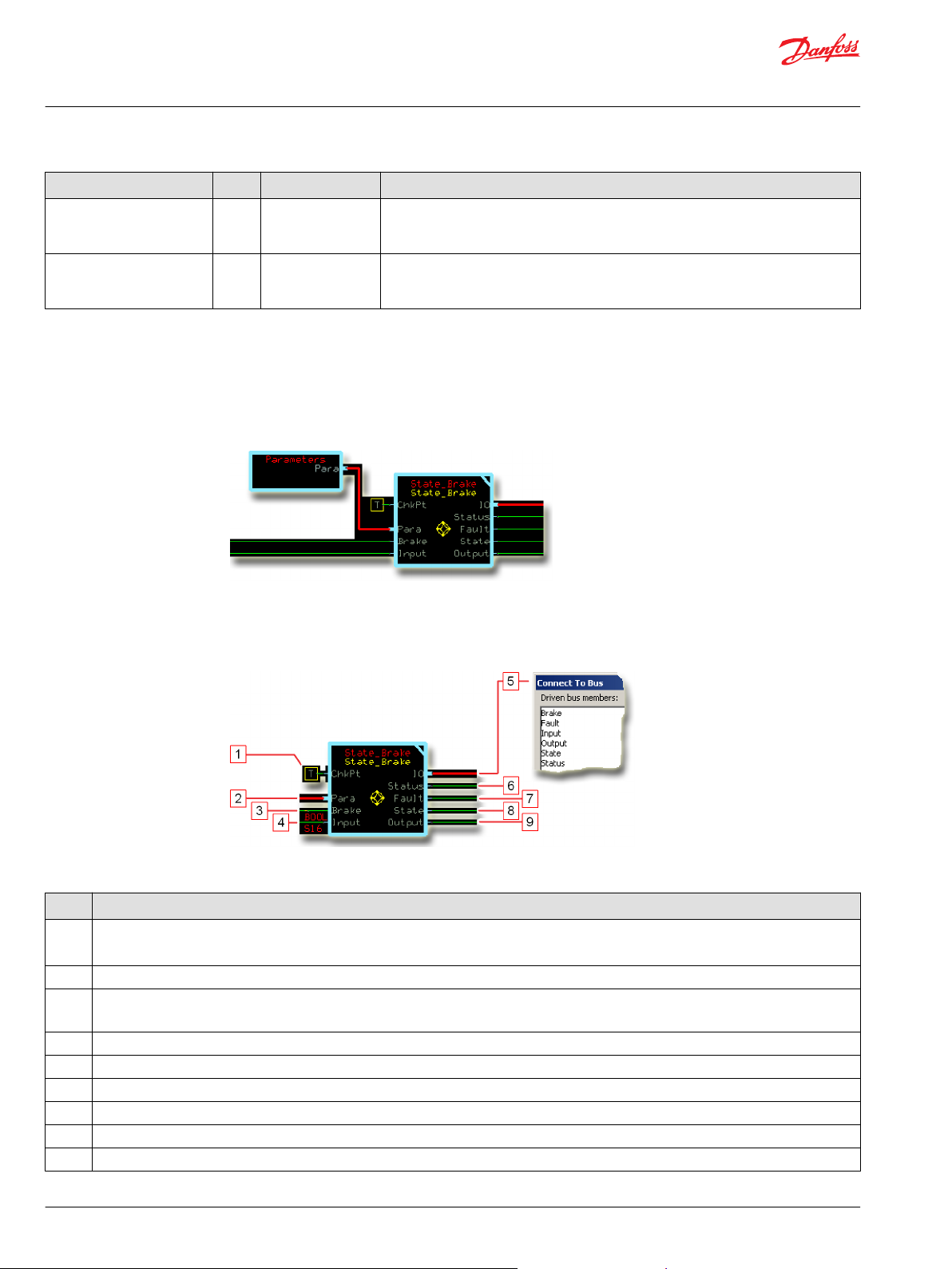
User Manual
PLUS+1® Compliant Function Block Library—Control Function Blocks
State_Brake Function Block
Item Type Range Description
Sft_Strt_Brake U16 0–10000 The non-linear, soft-start portion of the Dec_Tm_Brake ramp as a percentage of this
ramp’s total time.
10000 = 100.00%.
Sft_End_Brake U16 0–10000 The non-linear, soft-end portion of the Dec_Tm_Brake ramp as a percentage of this
ramp’s total time.
10000 = 100.00%.
About the Para Input
Typically, you input parameter (configuration) values from an external page to this function block
through its Para input.
The Parameters page in the following figure has memory component for each of the function block’s
parameters.
Function Block Connections
Connections you can make with the function block are described.
Function Block Connections
Description
Item
1.
2.
3.
4.
5. Outputs a bus with all of the function block's input and output signals.
6. Reports the status of the function block.
7. Reports the faults of the function block.
8.
9.
True—include the function block’s built-in Advanced Checkpoint with Namespace in the compiled LHX download file.
•
False—exclude the function block’s built-in Advanced Checkpoint with Namespace components from the compiled LHX download file.
•
Input for the acceleration and deceleration parameters that set how this function block’s Output ramps in response to changes in its Input.
True—ignore the Input value and apply the Brake parameters to ramp the Output value to 0.
•
False—apply the appropriate acceleration and deceleration parameters to the Output value in response to changes in the Input value.
•
Command signal to be ramped.
Reports the function block’s current state.
The Input command after ramping.
86 | © Danfoss | January 2019 11062085 | AQ284462219091en-000101
Page 87
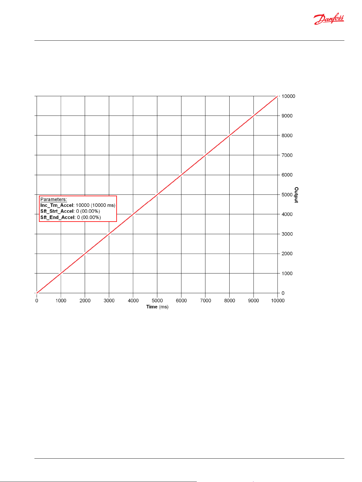
User Manual
PLUS+1® Compliant Function Block Library—Control Function Blocks
State_Brake Function Block
Function Block Examples
Use the following examples to understand how configuration changes impact the output of the function
block.
The parameters applied in this figure make the ramp completely linear.
©
Danfoss | January 2019 11062085 | AQ284462219091en-000101 | 87
Page 88
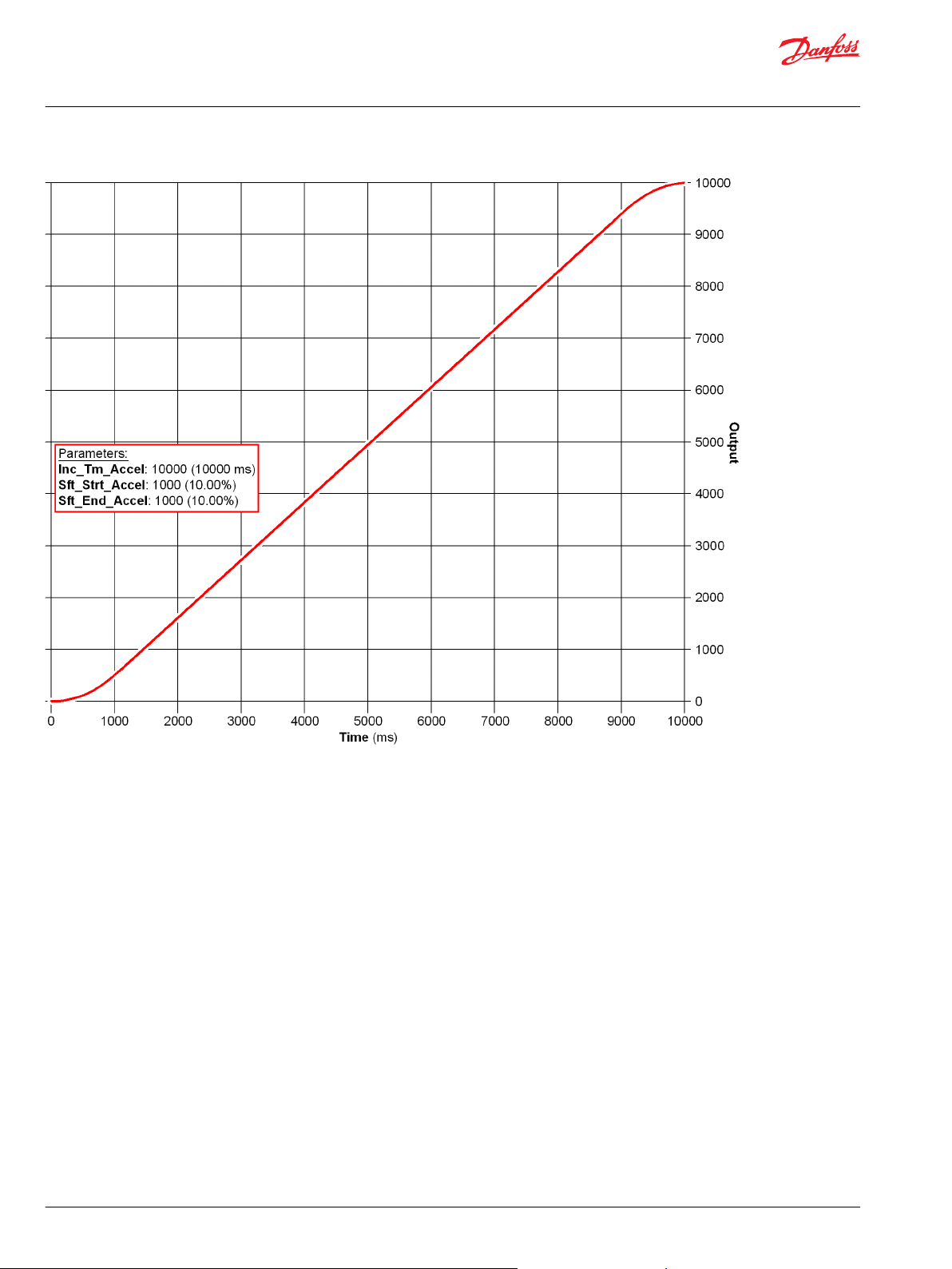
User Manual
PLUS+1® Compliant Function Block Library—Control Function Blocks
State_Brake Function Block
With the parameters shown in this figure, the:
88 | © Danfoss | January 2019 11062085 | AQ284462219091en-000101
Page 89
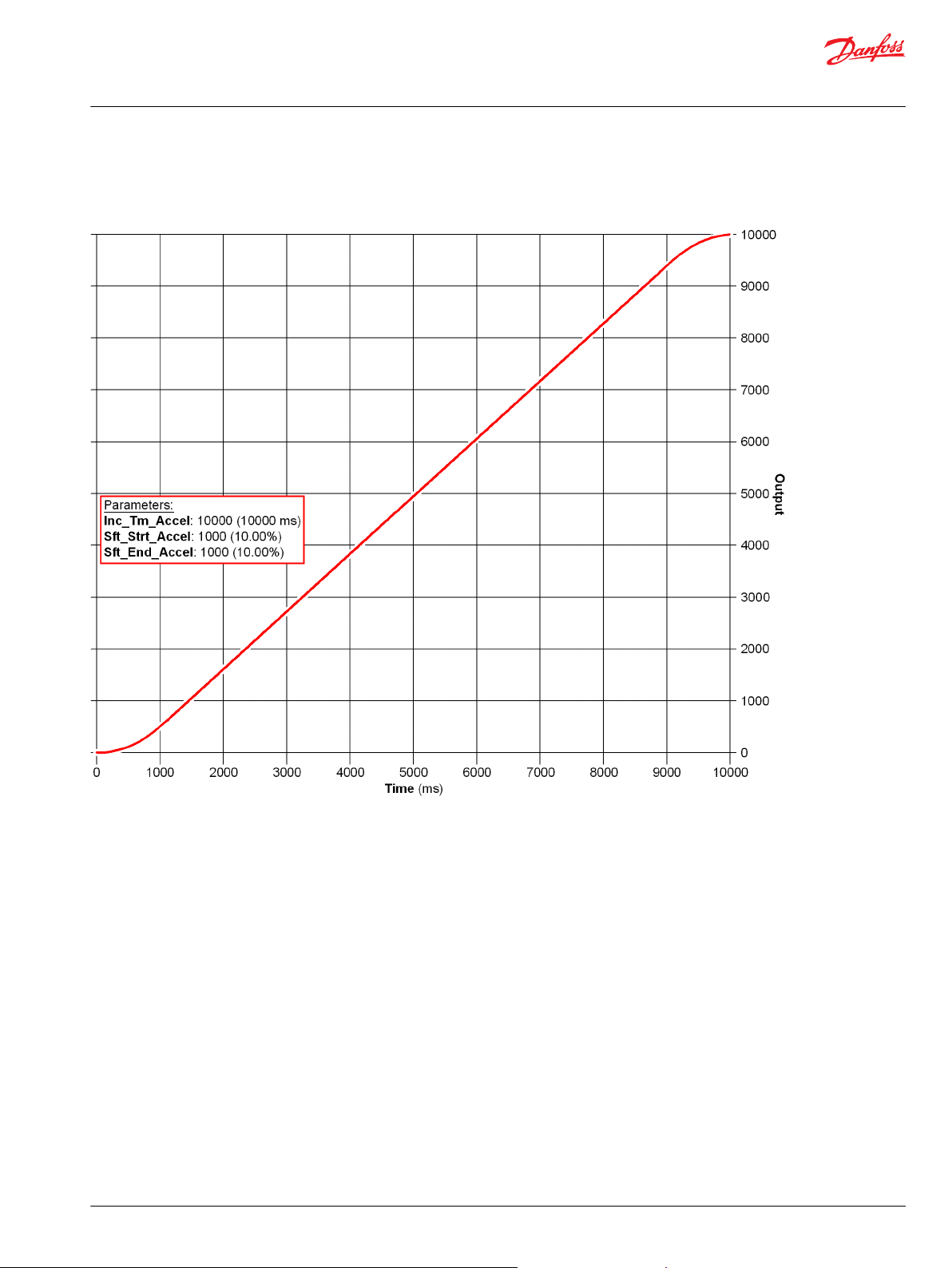
User Manual
PLUS+1® Compliant Function Block Library—Control Function Blocks
State_Brake Function Block
•
The Sft_Strt_Accel time starts at 0 ms and ends at 1000 ms.
•
The Sft_End_Accel time starts at 9000 ms and ends at 10000 ms.
With the parameters shown in this figure, the:
©
Danfoss | January 2019 11062085 | AQ284462219091en-000101 | 89
Page 90

User Manual
PLUS+1® Compliant Function Block Library—Control Function Blocks
State_Brake Function Block
•
The Sft_Strt_Accel time starts at 0 ms and ends at 2000 ms.
•
The Sft_End_Accel time starts at 8000 ms and ends at 10000 ms.
With the parameters shown in this figure, the:
•
Sft_Strt_Chg_Dir time starts at 0 ms and ends at 2000 ms.
•
Sft_End_Chg_Dir time starts at 8000 ms and ends at 10000 ms.
•
Dwell_Tm starts at 10000 ms and ends at 14000 ms.
•
Sft_Strt_Accel time starts at 14000 ms and ends at16000 ms.
•
Sft_End_Accel time starts at 22000 ms and ends at 24000 ms.
90 | © Danfoss | January 2019 11062085 | AQ284462219091en-000101
Page 91
User Manual
PLUS+1® Compliant Function Block Library—Control Function Blocks
State_Brake Function Block
With the parameters shown in this figure, the:
•
Dec_Tm_Coast time starts at 0 ms with an Output of 10000 and ends at 5000 ms with an Output of 5000.
•
50.00% decrease in the Output takes 5000 ms. (A 100.00% decrease in the Output takes 10000 ms.)
•
Sft_Strt_Coast time starts at 0 ms and ends at 500 ms.
•
Sft_End_Coast time starts at 4500 ms and ends at 5000 ms.
•
Sft_Strt_Coast and Sft_End_Coast times are equal to 10.00% of the ramp time and each take 500 ms.
Status and Fault Logic
Use status and fault codes to determine proper program operation.
©
Danfoss | January 2019 11062085 | AQ284462219091en-000101 | 91
Page 92

User Manual
PLUS+1® Compliant Function Block Library—Control Function Blocks
State_Brake Function Block
Status Logic
This topic describes how status logic is indicated for the function block.
Condition Hex
Invalid setup. 0x8008 1000
*
Bit 16 set to 1 identifies a standard Danfoss status or fault code.
Condition Hex
Input value is too low. 0x8001 0001 Input value < -10000. Input limited to -10000.
Input value is too high. 0x8002 0010 Input value > 10000. Input limited to 10000.
*
Bit 16 set to 1 identifies a standard Danfoss status or fault code.
*
Binary Cause Response Correction
A Sft_Strt or Sft_End
•
value is out-of range.
The sum ofSft_Strt and
•
Sft_End is greater than
10000.
The out-of-range Sft_Strt or
Sft_End value is limited to
10000.
Fault Logic
This topic describes how fault logic is indicated for the function block.
*
Binary Cause Response Correction
Return the Sft_Strt or Sft_End
parameter to the valid range.
Return the Input to the valid
range.
Identical Function Blocks Need Different Namespace Values to Successfully Compile
If you use the same function block more than once in an application, you must change each function
block’s namespace value to avoid compiler errors.
All function blocks contain Advanced Checkpoint with Namespace components that enable the PLUS+1
Service Tool to read block input and output values.
Some function blocks contain non-volatile memory components that store function block operating
parameters.
Both these components use memory names (“aliases”) to allocate memory. Identical memory names
cause compiler errors.
The namespace value adds a unique prefix to each component name to avoid errors. Keep each
namespace value short to save controller memory.
®
92 | © Danfoss | January 2019 11062085 | AQ284462219091en-000101
Page 93

User Manual
PLUS+1® Compliant Function Block Library—Control Function Blocks
State_Brake Function Block
Change Namespace Value
To successfully compile your application, change the namespace value for function blocks that are used
more than once in an application.
1. In the PLUS+1® GUIDE menu bar, click the Query/Change button.
2. Click on the function block whose namespace you want to set to a unique value.
The Edit Page window opens.
3. In the Edit Page window, enter a meaningful Namespace value.
Namespace values are case-sensitive.
•
To save controller memory, use a short namespace value.
•
4. Press Enter.
5. Repeat these steps to enter unique namespace values for other identical function blocks.
©
Danfoss | January 2019 11062085 | AQ284462219091en-000101 | 93
Page 94

User Manual
PLUS+1® Compliant Function Block Library—Control Function Blocks
State_Brake Function Block
IEC 61508-3 Annex D Supplemental Information
The following table provides IEC 61508-3 Annex D supplemental information.
Item
Function block name State_Brake.
Function block version 4.0.
Function block development
environment
Compatible hardware
Function block developed in
compliance with
Competence required of
function block integrator
Contacting Danfoss
Description
PLUS+1® GUIDE version 8.1 and later.
Verified in the PLUS+1® GUIDE compile process.
When the PLUS+1® GUIDE compiler finds a function block that is incompatible with hardware, it aborts the compile
process and logs an error message. The error message gives the location of the function block and states “Error 80:
component not supported in hwd.”
Danfoss Software Product Development Process (PDP), which includes ISO 9001 and IEC 61508-3 standards.
The knowledge, competence, and training required to:
Understand this manual.
•
Use the PLUS+1® GUIDE program to develop a machine control application.
•
Follow quality software practices to develop a machine control application.
•
https://www.danfoss.com/en/products/software/dps/plus1-software-services-support-and-training/plus1-support-andservices
94 | © Danfoss | January 2019 11062085 | AQ284462219091en-000101
Page 95

User Manual
PLUS+1® Compliant Function Block Library—Control Function Blocks
©
Danfoss | January 2019 11062085 | AQ284462219091en-000101 | 95
Page 96

Danfoss
Power Solutions GmbH & Co. OHG
Krokamp 35
D-24539 Neumünster, Germany
Phone: +49 4321 871 0
Danfoss
Power Solutions ApS
Nordborgvej 81
DK-6430 Nordborg, Denmark
Phone: +45 7488 2222
Danfoss
Power Solutions (US) Company
2800 East 13th Street
Ames, IA 50010, USA
Phone: +1 515 239 6000
Danfoss
Power Solutions Trading
(Shanghai) Co., Ltd.
Building #22, No. 1000 Jin Hai Rd
Jin Qiao, Pudong New District
Shanghai, China 201206
Phone: +86 21 3418 5200
Products we offer:
Comatrol
www.comatrol.com
Turolla
www.turollaocg.com
Hydro-Gear
www.hydro-gear.com
Daikin-Sauer-Danfoss
www.daikin-sauer-danfoss.com
DCV directional control
•
valves
Electric converters
•
Electric machines
•
Electric motors
•
Hydrostatic motors
•
Hydrostatic pumps
•
Orbital motors
•
PLUS+1® controllers
•
PLUS+1® displays
•
PLUS+1® joysticks and
•
pedals
PLUS+1® operator
•
interfaces
PLUS+1® sensors
•
PLUS+1® software
•
PLUS+1® software services,
•
support and training
Position controls and
•
sensors
PVG proportional valves
•
Steering components and
•
systems
Telematics
•
Danfoss Power Solutions is a global manufacturer and supplier of high-quality hydraulic and
electric components. We specialize in providing state-of-the-art technology and solutions
that excel in the harsh operating conditions of the mobile off-highway market as well as the
marine sector. Building on our extensive applications expertise, we work closely with you to
ensure exceptional performance for a broad range of applications. We help you and other
customers around the world speed up system development, reduce costs and bring vehicles
and vessels to market faster.
Danfoss Power Solutions – your strongest partner in mobile hydraulics and mobile
electrification.
Go to www.danfoss.com for further product information.
We offer you expert worldwide support for ensuring the best possible solutions for
outstanding performance. And with an extensive network of Global Service Partners, we also
provide you with comprehensive global service for all of our components.
Local address:
Danfoss can accept no responsibility for possible errors in catalogues, brochures and other printed material. Danfoss reserves the right to alter its products without notice. This also applies to products
already on order provided that such alterations can be made without subsequent changes being necessary in specifications already agreed.
All trademarks in this material are property of the respective companies. Danfoss and the Danfoss logotype are trademarks of Danfoss A/S. All rights reserved.
©
Danfoss | January 2019 11062085 | AQ284462219091en-000101
 Loading...