

Page 1
Installation Instructions
Control Cassettes
®
VLT
AutomationDrive FC 360
There are 3 types of control cassettes for VLT
AutomationDrive FC 360:
Standard control cassette (132B0255)
•
Control cassette with PROFIBUS (132B0256)
•
Control cassette with PROFINET (132B0257)
•
The installation instructions in this document apply to all of
them. For control cassette with PROFIBUS and control cassette
with PROFINET, make sure to mount the PROFIBUS/PROFINET
decoupling kit after mounting the control cassette. Instructions
on mounting the decoupling kit can be found in the kit
package.
®
Items Supplied
1 of the 3 types of control cassettes:
•
- Standard control cassette.
- Control cassette with PROFIBUS.
- Control cassette with PROFINET.
Screws
•
PROFIBUS/PROFINET decoupling kit
•
Voltage [V] Minimum waiting time (minutes)
415
380–480 0.37–7.5 kW 11–75 kW
High voltage may be present even when the warning LEDs are o!
Tab le 1.1 Di scharge Time
Refer to the quick guide for detailed information about safe
installation of the frequency converter.
Mounting
1. Remove the old control cassette. See the chapter
Assembly and Disassembly in the service manual for
instructions to remove a control cassette.
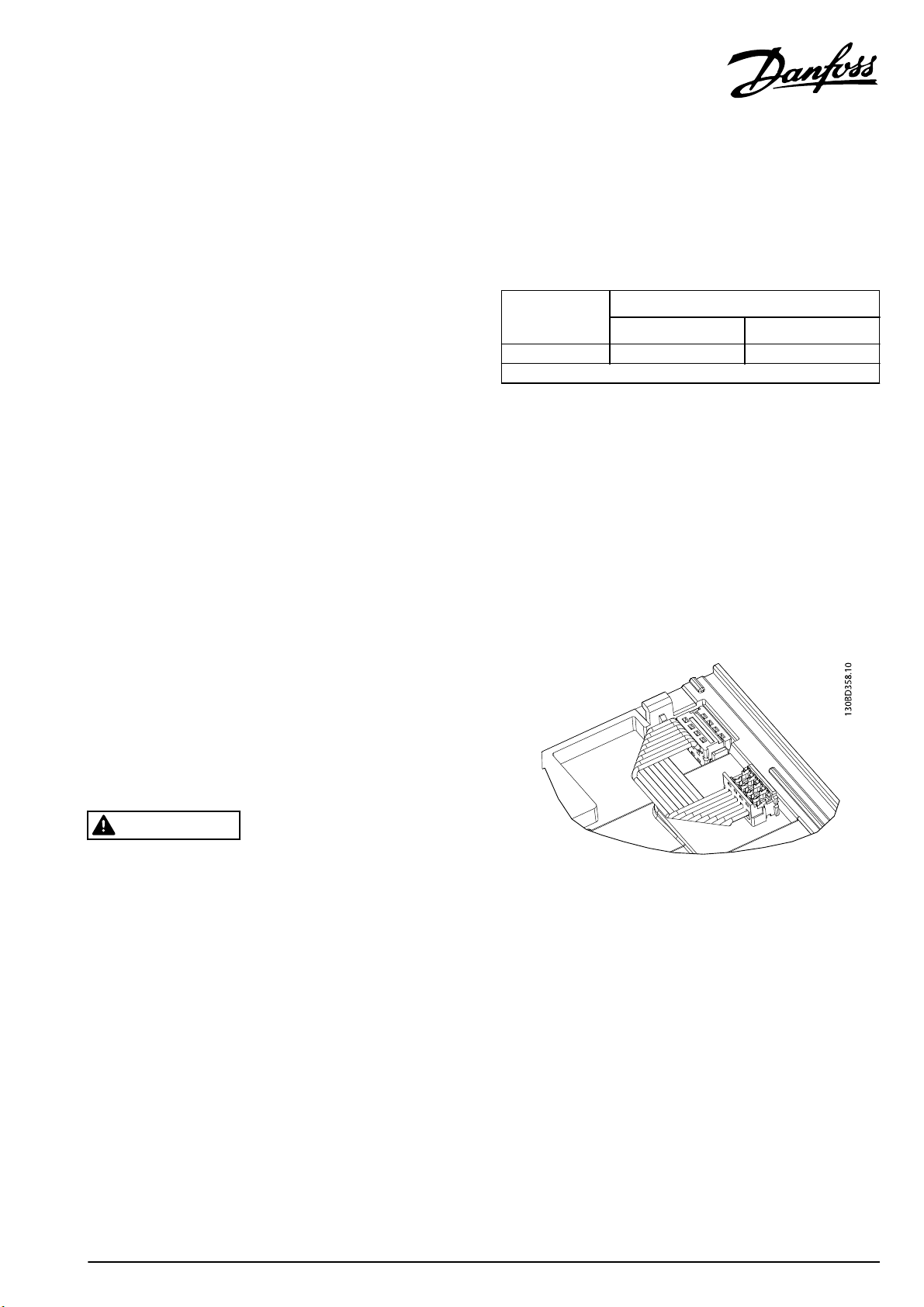
2. Connect the control cassette with the frequency
converter, bending the cable as shown in
Illustration 1.1.
Safety Instructions
WARNING
DISCHARGE TIME
The frequency converter contains DC-link capacitors, which
can remain charged even when the frequency converter is
not powered. Failure to wait the specied time after power
has been removed before performing service or repair work,
could result in death or serious injury.
Disconnect AC mains, permanent magnet type
•
motors, and remote DC-link power supplies,
including battery back-ups, UPS, and DC-link
connections to other frequency converters.
Wait for the capacitors to discharge fully, before
•
performing any service or repair work. The duration
of waiting time is specied in Table 1.1.
Illustration 1.1 Bend the Connection Cable
Danfoss A/S © 05/2015 All rights reserved. MI06C302
Page 2
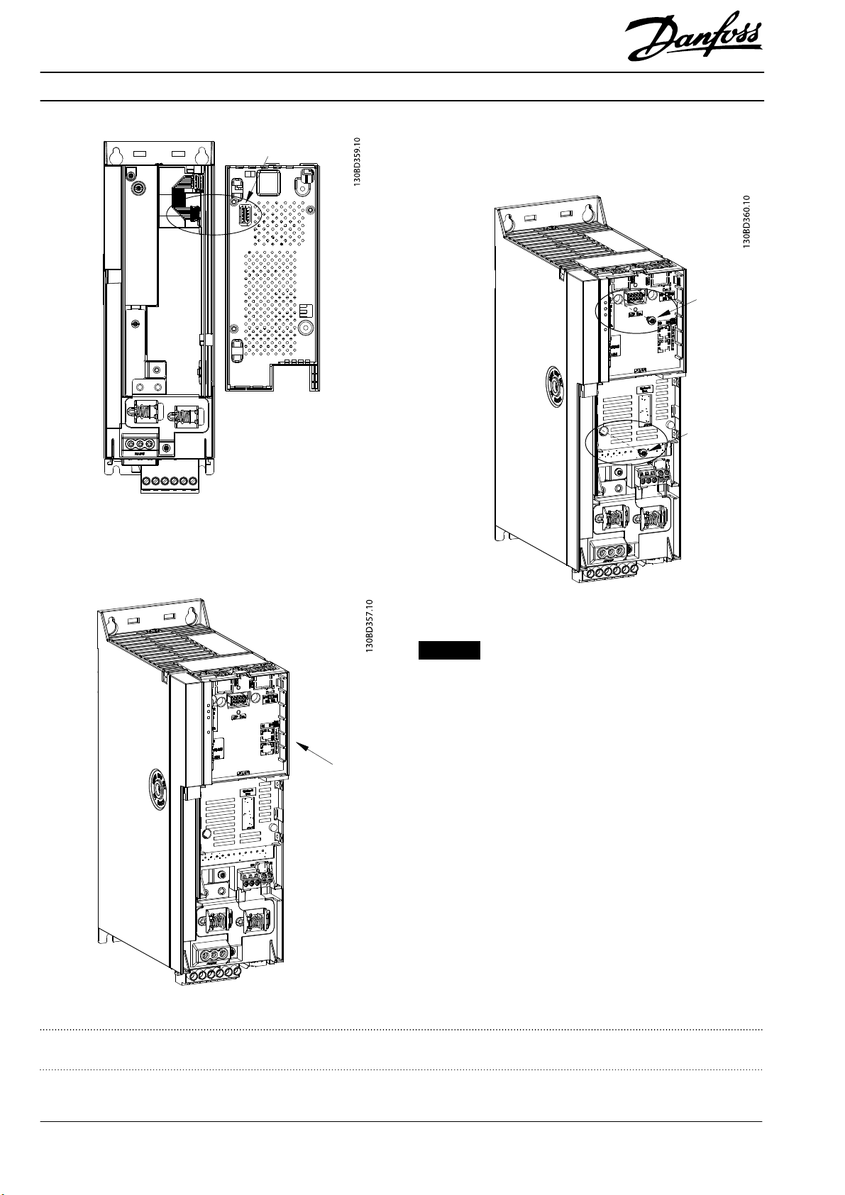
Illustration 1.2 Connection Point on the Control Cassette
4. Fasten the control cassette on the frequency
converter using 2 screws (supplied). Tightening
torque 0.7–1.0 Nm.
3. Place the control cassette on the frequency converter
and slide it into place.
Illustration 1.4 Tighten Screws
NOTICE
For the new control cassette to be properly recognised by
the frequency converter, update the software in the
frequency converter every time a new control cassette is
installed. For details about how to update the software, see
the section Flashing of Frequency Converter after Control Card
Replacement in the service manual.
Illustration 1.3 Slide the Control Cassette into Place
Danfoss can accept no responsibility for possible errors in catalogues, brochures and other printed material. Danfoss reserves the right to alter its products without notice. This also applies to products already on
order provided that such alterations can be made without subsequential changes being necessary in specifications already agreed. All trademarks in this material are property of the respective companies. Danfoss
and the Danfoss logotype are trademarks of Danfoss A/S. All rights reserved.
Danfoss A/S
Ulsnaes 1
DK-6300 Graasten
vlt-drives.danfoss.com
MI06C302132R0208 05/2015
*MI06C302*
 Loading...