

Page 1

Installation Guide
Control Card VLT® FC Series
1 Introduction
1.1 Compatible Drives
This guide describes the replacement of the control card in:
• VLT® HVAC Drive FC 102.
• VLT® Refrigeration Drive FC 103.
• VLT® AQUA Drive FC 202.
• VLT® AutomationDrive FC 301/FC 302.
• VLT® Lift Drive LD 302.
1.2 Safety Instructions
Only Danfoss authorized, qualified personnel is allowed to repair this equipment.
WARNING
DISCHARGE TIME
The drive contains DC-link capacitors, which can remain charged even when the drive is not powered. High voltage can be
present even when the warning indicator lights are off.
Failure to wait the specified time after power has been removed before performing service or repair work could result in death
or serious injury.
Stop the motor.
-
Disconnect AC mains, permanent magnet type motors, and remote DC-link supplies, including battery back-ups, UPS, and
-
DC-link connections to other drives.
Wait for the capacitors to discharge fully. The minimum waiting time is specified in table Discharge time and is also visible
-
on the nameplate on top of the drive.
Before performing any service or repair work, use an appropriate voltage measuring device to make sure that the capacitors
-
are fully discharged.
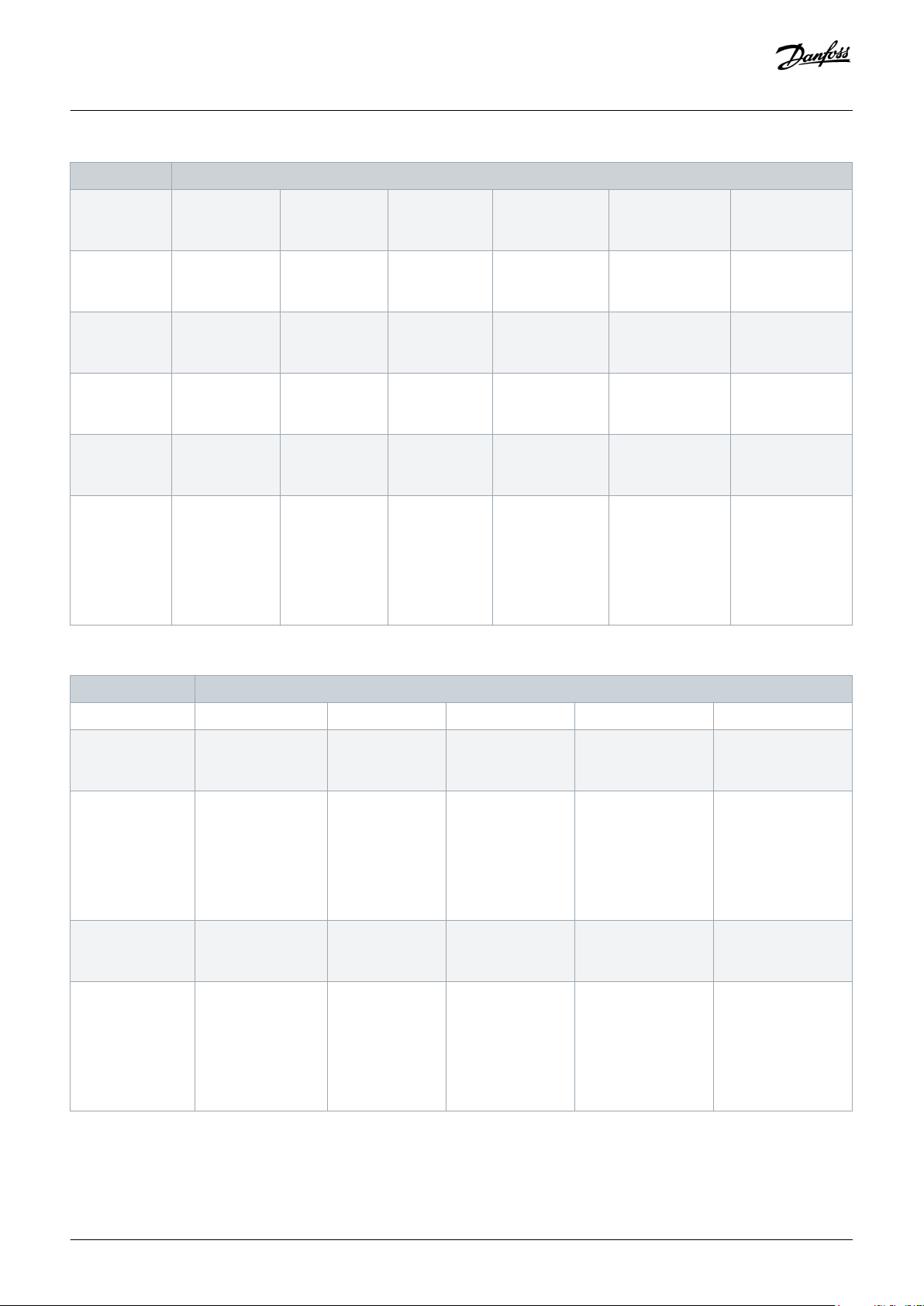
Table 1: Discharge Time, VLT® HVAC Drive FC 102
Voltage [V] Minimum waiting time (minutes)
4 7 15 20 30 40
200–240 1.1–3.7 kW
(1.50–5 hp)
– 5.5–45 kW
(7.5–60 hp)
– – –
380–480 1.1–7.5 kW
(1.50–10 hp)
Danfoss A/S © 2018.09
– 11–90 kW
(15–121 hp)
– – 315–1000 kW
(450–1350 hp)
AN279051429263en-000101 / 130R0788 | 1
Page 2
Installation Guide | Control Card VLT® FC Series
Voltage [V] Minimum waiting time (minutes)
Introduction
400 – – – 90–315 kW
(121–450 hp)
500 – – – 110–355 kW
(150–500 hp)
525 – – – 75–315 kW
(100–450 hp)
525–600 1.1–7.5 kW
(1.50–10 hp)
– 11–90 kW
(15–121 hp)
– – –
690 – – – 90–315 kW
(100– 350 hp)
525–690 – 1.1–7.5 kW
(1.50–10 hp)
11–90 kW
(15–121 hp)
– 400–1400 kW
– –
– –
– –
– –
–
(500–1550 hp)
450–1400 kW
(600–1550 hp)
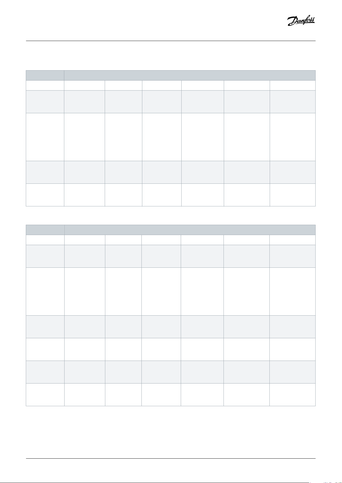
Table 2: Discharge Time, VLT® Refrigeration Drive FC 103
Voltage [V] Minimum waiting time (minutes)
4 7 15 20 40
200–240 0.25–3.7 kW
– 5.5–37 kW
(0.34–5 hp)
380–480 0.25–7.5 kW
– 11–75 kW
(0.34–10 hp)
525–600 0.75–7.5 kW
– 11–75 kW
(1.0–10 hp)
525–690 – 1.5–7.5 kW
(2–10 hp)
(7.5–50 hp)
(15–100 hp)
(15–100 hp)
11–75 kW
(15–100 hp)
– –
110–315 kW
(150–450 hp)
– –
55–400 kW
(75–400 hp)
355–450 kW
(500–600 hp)
355–560 kW
(500–750 hp)
450–630 kW
(600–750 hp)
450–800 kW
(600–950 hp)
2 | Danfoss A/S © 2018.09
AN279051429263en-000101 / 130R0788
Page 3
Installation Guide | Control Card VLT® FC Series
Table 3: Discharge Time, VLT® AQUA Drive FC 202
Voltage [V] Minimum waiting time (minutes)
4 7 15 20 30 40
Introduction
200–240 0.25–3.7 kW
(0.34–5 hp)
380–480 0.25–7.5 kW
(0.34–10 hp)
525–600 0.75–7.5 kW
(1–10 hp)
525–690 – 1.1–7.5 kW
Table 4: Discharge Time, VLT® AutomationDrive FC 301/FC 302
– 5.5–37 kW
(7.5–50 hp)
– 11–75 kW
(15–100 hp)
– 11–90 kW
(15–121 hp)
11–90 kW
(1.5–10 hp)
(10–100 hp)
Voltage [V] Minimum waiting time (minutes)
4 7 15 20 30 40
200–240 0.25–3.7 kW
– 5.5–37 kW
– – –
110–315 kW
– 315–1000 kW
(150–450 hp)
– 400–1400 kW
(400–1550 hp)
75–400 kW
– 450–800 kW
(75–400 hp)
– – –
(450–1350 hp)
355–560 kW
(500–750 hp)
–
(450–950 hp)
(0.34–5 hp)
380–500 0.25–7.5 kW
(0.34–10 hp)
– 11–75 kW
(7.5–50 hp)
(15–100 hp)
90–200 kW
(150–350 hp)
400 – – – 90–315 kW
(125–450 hp)
500 – – – 110–355 kW
(150–450 hp)
525 – – – 55–315 kW
(75–400 hp)
525–600 0.75–7.5 kW
(1–10 hp)
– 11–75 kW
(15–100 hp)
– – –
250–500 kW
(450–750 hp)
– –
– –
– –
250–800 kW
(450–1350 hp)
315–500 kW
(500–750 hp)
Danfoss A/S © 2018.09
AN279051429263en-000101 / 130R0788 | 3
Page 4

Installation Guide | Control Card VLT® FC Series
Voltage [V] Minimum waiting time (minutes)
Introduction
525–690 – 1.5–7.5 kW
(2–10 hp)
690 – – – 55–315 kW
Table 5: Discharge Time, VLT® Lift Drive LD 302
Voltage [V] Minimum waiting time (minutes)
4 15
380–480 0.25–7.5 kW
(0.34–10 hp)
11–75 kW
(15–100 hp)
37–315 kW
(50–450 hp)
(75–400 hp)
1.3 Items Supplied
The following is supplied:
• Control card.
355–1200 kW
(450–1550 hp)
– –
11–75 kW
(15–100 hp)
355–2000 kW
(450–2050 hp)
355–710 kW
(400–950 hp)
1.4 Tools
Only 2 tools are required for replacing the control card:
• Torx 10 screwdriver.
• Flat-head screwdriver.
1.5 More Items Required
• An FC Series drive.
4 | Danfoss A/S © 2018.09
AN279051429263en-000101 / 130R0788
Page 5

1
2
e30bf717.11
Installation Guide | Control Card VLT® FC Series
2 Replacement
2.1 Overview
Replacement
1 LCP 2 Blind cover
Illustration 1: LCP and Blind Cover
Danfoss A/S © 2018.09
AN279051429263en-000101 / 130R0788 | 5
Page 6

e30bf718.11
e30bf719.11
Installation Guide | Control Card VLT® FC Series
2.2 Replacing the Control Card
Procedure
1. Remove the LCP and the blind cover.
Replacement
Illustration 2: Removing the LCP
Illustration 3: Removing the Blind Cover
2. Remove the LCP cradle.
6 | Danfoss A/S © 2018.09
AN279051429263en-000101 / 130R0788
Page 7

e30bf720.11
1
2
3
e30bf721.12
Installation Guide | Control Card VLT® FC Series
Replacement
Illustration 4: Removing the LCP Cradle
3. Remove all control cables from the metal bracket (spring-loaded).
4. Remove any A, B, or C options that may be installed.
5. Remove the I/O terminals.
1 Location of A option
3 I/O terminals
2 Location of B option
Illustration 5: Location of Options and I/O Terminals
6. Unscrew the 3 T10 screws and remove the cable shield.
7. Remove the plastic cover underneath the cable shield.
Danfoss A/S © 2018.09
AN279051429263en-000101 / 130R0788 | 7
Page 8

1
3
2
e30bf722.11
e30bg832.10
Installation Guide | Control Card VLT® FC Series
Replacement
1 Cable shield
2 MCO ribbon cable
3 T10 screws
Illustration 6: Location of the Cable Shield, Screws, and MCO Ribbon Cable (Control Card without MCB 159)
Illustration 7: Control Card with MCB 159
8. Unscrew the 2 T10 screws holding the control card EMC shield (4 screws if MCO is installed).
A If MCO is installed, remove the MCO ribbon cable.
B If the VLT® Sensorless Safety MCB 159 option is installed, it is not possible to remove the ribbon cable before removing the
control card EMC shield.
8 | Danfoss A/S © 2018.09
AN279051429263en-000101 / 130R0788
Page 9

2
1
e30bf723.11
Installation Guide | Control Card VLT® FC Series
9. Remove the control card EMC shield.
A If the MCB 159 is installed, lift the left side of the control card EMC shield first, then lift the right side until it is possible to
remove the MCB 159 ribbon cable. Otherwise, there is a risk to destroy the cable or the connector. When the ribbon cable is
removed, the EMC shield is separated from the control card.
Replacement
1 T10 screws 2 Control card
Illustration 8: Screws and EMC Shield
10. Unscrew the 3 T10 screws and remove them.
11. Gently remove the control card from the upper-right socket. Avoid overbending and contact with electronic components.
Danfoss A/S © 2018.09
AN279051429263en-000101 / 130R0788 | 9
Page 10

1
2
e30bf724.11
Installation Guide | Control Card VLT® FC Series
Replacement
Illustration 9: Control Card and T10 Screws
The control card can now be replaced. Reassemble the new control card in reverse order.
10 | Danfoss A/S © 2018.09
AN279051429263en-000101 / 130R0788
Page 11

Danfoss A/S © 2018.09
AN279051429263en-000101 / 130R0788 | 11
Page 12

Installation Guide | Control Card VLT® FC Series
Replacement
Danfoss can accept no responsibility for possible errors in catalogues, brochures and other printed material. Danfoss reserves the right to alter its products without notice. This also applies to products
already on order provided that such alterations can be made without subsequential changes being necessary in specifications already agreed. All trademarks in this material are property of the respective
companies. Danfoss and the Danfoss logotype are trademarks of Danfoss A/S. All rights reserved.
Danfoss A/S
Ulsnaes 1
DK-6300 Graasten
vlt-drives.danfoss.com
Danfoss A/S © 2018.09
MI93A202
*MI93A202
*
AN279051429263en-000101/ 130R0788
 Loading...