

Installation Instruction
Danfoss Connecto NA connection kits

2 | © Danfoss | 2018.07
VILWE112
Installation Instruction
Danfoss Connecto NA connection kits
Table of contents
1 Overview . . . . . . . . . . . . . . . . . . . . . . . . . . . . . . . . . . . . . . . . . . . . . . . . 3
2 Certifications / Approvals . . . . . . . . . . . . . . . . . . . . . . . . . . . . . . . . . . . . . 3
3 Technical data. . . . . . . . . . . . . . . . . . . . . . . . . . . . . . . . . . . . . . . . . . . . . 4
4 Safety . . . . . . . . . . . . . . . . . . . . . . . . . . . . . . . . . . . . . . . . . . . . . . . . . . 4
5 Kit contents . . . . . . . . . . . . . . . . . . . . . . . . . . . . . . . . . . . . . . . . . . . . . . 5
6 Component identification . . . . . . . . . . . . . . . . . . . . . . . . . . . . . . . . . . . . . 6
7 Installation. . . . . . . . . . . . . . . . . . . . . . . . . . . . . . . . . . . . . . . . . . . . . . . 7
8 Attachment to pipes. . . . . . . . . . . . . . . . . . . . . . . . . . . . . . . . . . . . . . . . 13
9 Safety . . . . . . . . . . . . . . . . . . . . . . . . . . . . . . . . . . . . . . . . . . . . . . . . . 17
10 Sécurité et avertissements. . . . . . . . . . . . . . . . . . . . . . . . . . . . . . . . . . . . 18
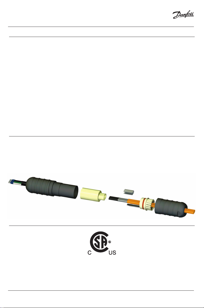
1 Overview
Danfoss Connecto NA is a family of connection kits for self-regulating heating cables (trace heaters).
The Connecto NA connection kits are simple and safe to use, yet faster to install and more cost effective
than conventional systems. They can be used with Danfoss PX/RX heating cables in fixed equipment
heating systems for multiple applications (e.g. heating of pipes, roof and gutter de-icing etc.).
2 Certifications / Approvals
Connecto NA
for use with
VILWE112
connection for self-regulating heating cable for roof and gutter de-icing, pipe applications etc. ;
Danfoss PX/RX
heating cable only.
© Danfoss | 2018.07 | 3
Installation Instruction
Danfoss Connecto NA connection kits
3 Technical data
Operating voltage max. 250 VAC
Current max. 16 A
Ambient temperature range -40 °F to 185 °F / -40 °C to 85° C
Operation temperature range -40 °F to 150 °F / -40 °C to 65 °C
Protection class NEMA Type 4X / IP66
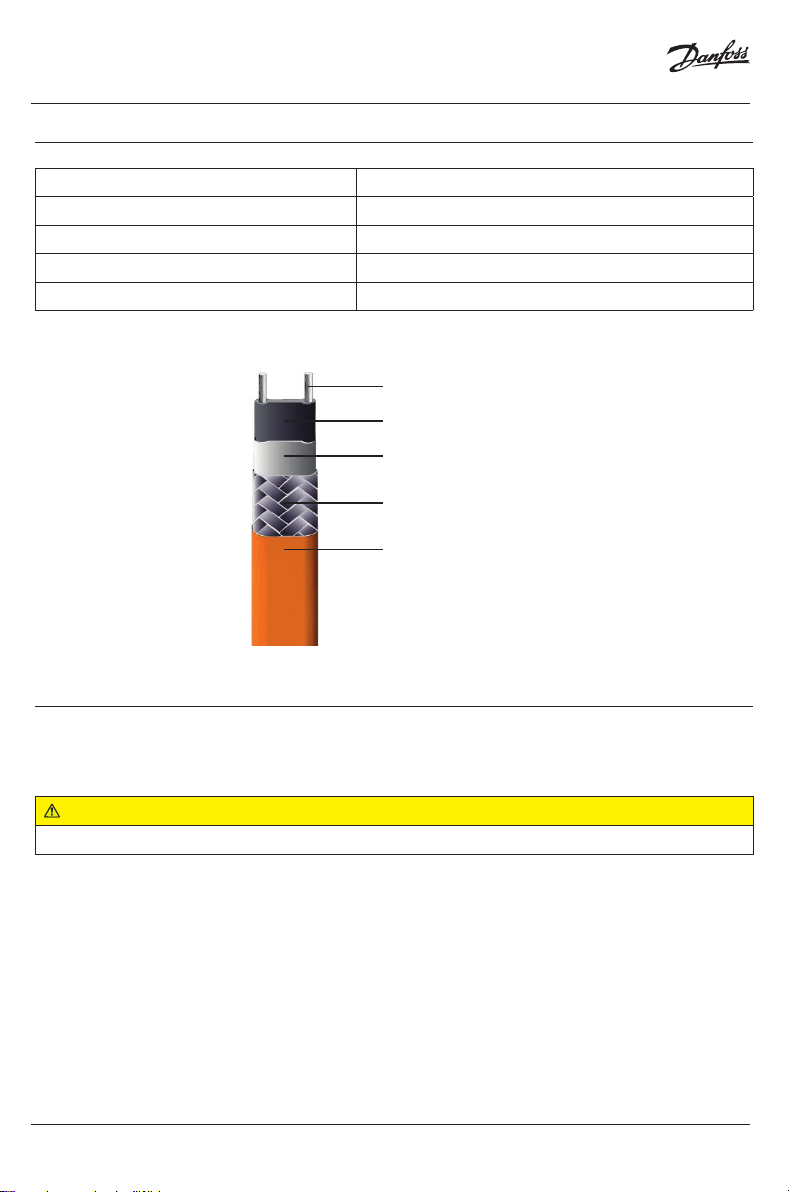
The following terms describe the parts of the heating cable within these instructions:
bus wire
heating matrix
insulation jacket
grounding braid
outer jacket
4 Safety
For safe installation and operation of the Connecto NA the technical requirements and instructions
given in this manual must be followed.
WARNING:
Risk of fire or electrical shock. Follow these guidelines to avoid personal injury or material damage.
• All electrical systems and installations must comply with Danfoss requirements and be installed in
accordance with the relevant electrical codes and any other applicable national and local codes.
• The US and Canadian electrical codes require ground fault protection to be provided for all trace
heating circuits.
• Install the connection kit and heating cables carefully.
• The bending radius of the heating cable must be at least 1" (25 mm). Do not bend on the narrow
axis.
• Use the heating cables and connection kit in accordance with the intended purpose and strictly
comply with the operational data specified in section Technical Data.
4 | © Danfoss | 2018.07
VILWE112
Installation Instruction
Danfoss Connecto NA connection kits
• For roof and gutter applications use only the UV-resistant Danfoss RX-C ‘black’ heating cable (certified by the –WS mark on the device).
• Any defective component in a set must be replaced before installation.
• Keep all components and the heating cables dry before and during installation.
• To avoid short circuits, do not connect the heating cable bus wires together.
• When used for roof and gutter de-icing, the Connecto NA connection kit must be installed in a dry
place outside the gutter.
• For end seal installation silicone adhesive is used. Follow the safety instructions given on the packaging.
• Keep these instructions for future reference. If applicable, leave them with the end user.
• De-energize before installation or servicing.
• Use only original Danfoss accessories.
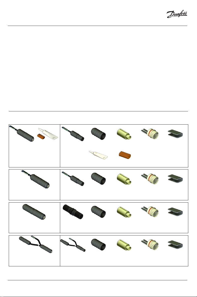
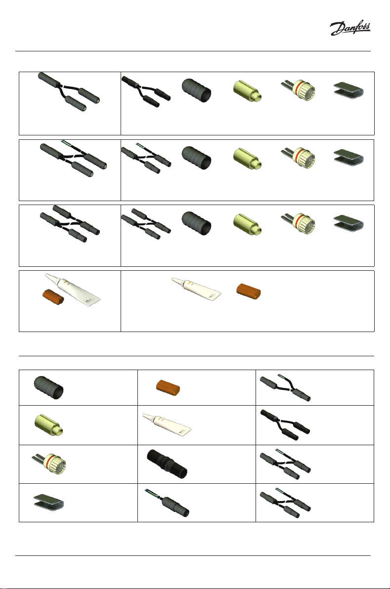
5 Kit contents
The following table lists the kit contents for each of the Connecto NA connection systems:
Connecto NA-B-PK
Power connection
with end seal
Connecto NA-B-P
Power connection
Connecto NA-B-S
Splice connection kit
Connecto NA-B-PS
Powered splice kit
VILWE112
1 × 1 × 1 × 1 × 1 ×
1 × 1 ×
1 × 1 × 1 × 1 × 1 ×
1 × 2 × 2 × 2 × 1 ×
1 × 2 × 2 × 2 × 1 ×
© Danfoss | 2018.07 | 5
Installation Instruction
Danfoss Connecto NA connection kits
Connecto NA-B-T
T-Connection kit
Connecto NA-B-PT
Powered T-Connection kit
Connecto NA-B-X
X-Connection kit
Connecto NA-B-E
Silicone end seal (5X)
6 Component identification
Threaded Cap End cap
1 × 3 × 3 × 3 × 3 ×
1 × 3 × 3 × 3 × 3 ×
1 × 4 × 4 × 4 × 4 ×
1 × 5 ×
Powered splice
assembly
6 | © Danfoss | 2018.07
Sleeve
Clamping
sleeve
Clamping
sheet
Silicone
adhesive
Splice
assem-bly
Power connec-
tion assembly
T-Assembly
Powered T-
Assembly
X-Assembly
VILWE112

Installation Instruction
7 Installation
Danfoss Connecto NA connection kits
Required tools / equipment.
The following tools and equipment are required for installation of the Connecto NA connection kits:
• Wire cutters
• Utility knife
• Tape measure
Cautions and warnings.
WARNING:
Risk of fire or electrical shock. De-energize all power circuits before installation or servicing. Always
use ground fault equipment within the heat tracing system.
• Double-check that all power circuits are de-energized before you begin your work.
• Make sure that you do not exceed the maximum heating circuit length for the heating cable
type you use. Refer to the design guide of the heating system.
Preparation of the heating cable.
WARNING:
Risk of short cuts and/or material damage. Keep the heating cable ends dry before and during
installation. Observe the heating cable’s installation instructions.
1
2
• Unroll the required heating cable in a straight line and cut to the correct length. Cut off the
heating cable ensuring a straight cut.
• Slide on the threaded cap and the clamping sleeve.
VILWE112
© Danfoss | 2018.07 | 7
3

Installation Instruction
Danfoss Connecto NA connection kits
• Remove 1 ⅝" (42 mm) of the outer jacket from the end of the heating cable.
• Slide the clamping sheet over the grounding braid right up to the outer jacket.
• Draw the grounding braid back over the clamping sheet.
4
5
• Make sure that the clamping sleeve’s orientation is correct in order that the blades fit into the
designated slots.
• Insert the heating cable into the sleeve until the heating cable is flush with the sleeve.
8 | © Danfoss | 2018.07
6
VILWE112

Installation Instruction
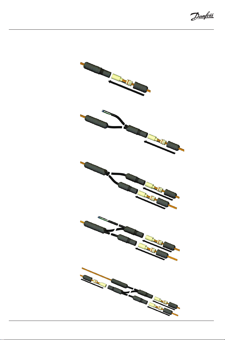
Connection of the heating cable
• Make sure that the tip of the assembly and the groove of the clamping sleeve are properly
aligned.
• Push the clamping sleeve against the sleeve and insert into the assembly.
Power connection, powered splice, T-, powered T and X-connection kits:
Danfoss Connecto NA connection kits
7
Splice kits:
• Completely screw together the threaded cap and the assembly.
WARNING:
Risk of fire or malfunction. Double-check that there is no gap left between the threaded cap and the
assembly.
VILWE112
© Danfoss | 2018.07 | 9
8
Installation Instruction
Danfoss Connecto NA connection kits
• If applicable, repeat steps 3 to 8 to connect all remaining heating cables:
Splice kit:
Powered splice kit:
T-Connection kit:
9
Powered T-Connection kit:
X-Connection kit:
10 | © Danfoss | 2018.07
VILWE112

Installation Instruction
Danfoss Connecto NA connection kits
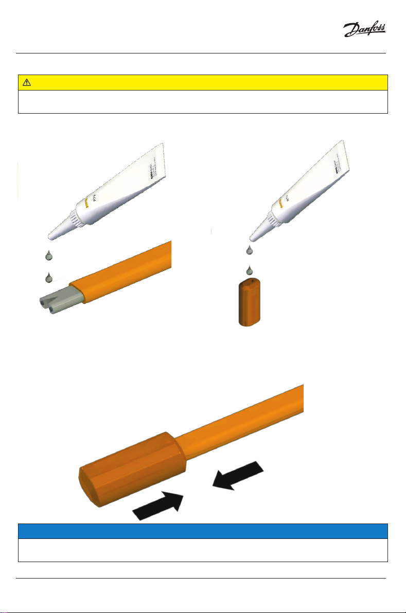
Installation of the end seal
• Cut the trace heater off straight.
• Remove ¾" (20 mm) of the outer jacket.
• Remove the exposed grounding braid. Make sure that the insulation jacket is not damaged.
10
11
• Cut in a triangle (¼" / 5 mm) between the bus wires.
12
© Danfoss | 2018.07 | 11VILWE112
Installation Instruction
WARNING:
The silicone adhesive may cause irritation to skin and eyes. Avoid eye contact. Avoid repeated or
prolonged skin contact. Follow the safety instructions given on the packaging.
• Put silicone adhesive onto the exposed insulating jacket and into the end cap.
Danfoss Connecto NA connection kits
13
• Push the end cap over the end of the trace heater.
NOTICE:
Allow the adhesive to cure for 20 minutes, then visually inspect. Full strength is reached after 24
hours.
12 | © Danfoss | 2018.07
14
VILWE112
Installation Instruction
Danfoss Connecto NA connection kits
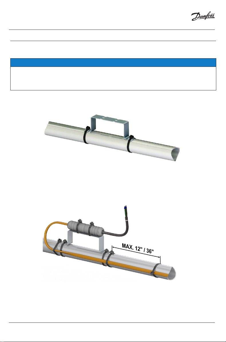
8 Attachment to pipes
Attachment methods.
NOTICE:
It is recommended to install the Danfoss Connecto NA connection kit connection kit on a mounting
bracket (“off-pipe”) to protect it from excessive temperatures (as shown on the left). However, when
used in moderate temperature conditions all Danfoss Connecto NA connection kits can also be
directly attached to the pipe (as shown in 1B).
Off-pipe installation:
• Attach the mounting bracket (see section Accessories on page 10) to the pipe using cable ties.
• Attach the Danfoss Connecto NA connection kit to the mounting bracket and the trace heater to
the pipe using polyester tape or cable ties.
• Make sure that the distance between 2 attachment points does not exceed 12" (300 mm) on plastic
pipes or 36" (900 mm) on steel pipes.
1A
© Danfoss | 2018.07 | 13VILWE112

Installation Instruction
Danfoss Connecto NA connection kits
On-pipe installation:
• Attach the trace heater and the Danfoss Connecto NA connection kit to the pipe using polyester tape or cable ties.
• Make sure that the distance between 2 attachment points does not exceed 12" (300 mm) on plastic
pipes or 36" (900 mm) on steel pipes.
Position on the pipe
• Depending on the Danfoss Connecto NA kit you use, the position on the pipe is as follows (note
that all Danfoss Connecto NA connection kits can be installed on a mounting bracket (“off-pipe”) or
directly on the pipe):
Power connection:
1B
2
Splice:
14 | © Danfoss | 2018.07
VILWE112

Installation Instruction
Powered splice:
T-Connection:
Danfoss Connecto NA connection kits
Powered T-Connection:
© Danfoss | 2018.07 | 15VILWE112

Installation Instruction
X-Connection:
Danfoss Connecto NA connection kits
16 | © Danfoss | 2018.07
VILWE112

Installation Instruction
Danfoss Connecto NA connection kits
9 Safety
WARNING:
Risk of fire or electrical shock. Follow these guidelines to avoid personal injury or material damage.
WARNING:
Risk of fire or electrical shock. De-energize all power circuits before installation or servicing. Always
use ground fault equipment within the heat tracing system.
WARNING:
Risk of short cuts and/or material damage. Keep the trace heater ends dry before and during installation. Observe the trace heater’s installation instructions.
WARNING:
Risk of fire or malfunction. Double-check that there is no gap left between the threaded cap and the
assembly.
WARNING:
The silicone adhesive may cause irritation to skin and eyes. Avoid eye contact. Avoid repeated or
prolonged skin contact. Follow the safety instructions given on the packaging.
NOTICE: The following instructions are provided in English only. Refer to lx.danfoss.com for the
French version.
© Danfoss | 2018.07 | 17VILWE112

Installation Instruction
Danfoss Connecto NA connection kits
10 Sécurité et avertissements
AVERTISSEMENT
Risque d’incendie ou d’électrocution. Suivez ces consignes pour éviter toute blessure ou dommage
matériel.
AVERTISSEMENT
Risque d’incendie ou d’électrocution. Mettre tous les circuits électriques hors tension avant toute
installation ou opération de maintenance. Toujours utiliser un dispositif de protection contre les
défauts à la terre au sein du système de traçage électrique.
AVERTISSEMENT
Risque de court-circuit et/ou de dommages matériels. Conservez les extrémités du câble chauffant
au sec avant et pendant toute la durée de l’installation. Respectez les consignes d’installation du
câble chauffant.
AVERTISSEMENT
Risque d’incendie ou de dysfonctionnement. Assurez-vous qu’il n’y a aucun espace entre le capuchon fileté et le raccord.
AVERTISSEMENT
La colle au silicone peut irriter la peau et les yeux. Eviter tout contact avec les yeux. Eviter tout contact répété ou prolongé avec la peau. Respectez les consignes de sécurité indiquées sur l’emballage.
AVIS: Les instructions qui suivent sont fournies en anglais uniquement. Veuillez vous référer au site
lx.danfoss.com pour la version française
18 | © Danfoss | 2018.07
VILWE112

Installation Instruction
Danfoss Connecto NA connection kits
© Danfoss | 2018.07 | 19VILWE112

Danfoss
11655 Crossroads Circle
Baltimore, MD 21220 USA
Phone: 1-888-DANFOSS (326-3677)
Fax: 416-352-5981
lx.danfoss.com
Danfoss can accept no responsibility for possible errors in catalogues, brochures and other printed material. Danfoss reserves the right to alter its products without
notice. This also applies to products already on order provided that such alterations can be made without subsequential changes being necessary in specifications
already agreed. All trademarks in this material are property of the respective companies. DEVI and the DEVI logo-type are trademarks of Danfoss A/S. All rights reserved.
20 | © Danfoss | 2018.07
VILWE112
 Loading...