

Page 1
Fitters’ Notes Condensing units
Contents Page
General information on operating Danfoss condensing units ....................................... 3
Equipment conguration .......................................................................... 3
Power supply and electrical equipment ........................................................ 3
Hermetic compressors ............................................................................. 4
Condensers and fans .............................................................................. 4
Stop valves ........................................................................................ 4
Receiver Pressure container ordinance ............................................................. 5
Terminal box ...................................................................................... 5
Safety pressure monitors .......................................................................... 5
Setup ............................................................................................. 5
Protective weather-proof housing .............................................................. 6
Careful installation ................................................................................ 6
Contamination and foreign particles ........................................................... 6
Doing the pipe work ........................................................................... 6
Tubing layout of the condensing units with 1-cylinder compressors
types TL, FR, NL, SC and SC-TWIN ........................................................... 6
Tubing layout of the condensing units with hermetic Maneurop®
reciprocating piston compressors, 1-2-4 cylinder ............................................ 8
Leak check .................................................................................... 8
Soldering ..................................................................................... 9
Protective gas ................................................................................. 9
Evacuating and lling ............................................................................ 10
Exceeding the max. allowable operational lling capacity and setting up outdoors .................11
General information: ......................................................................... 11
“Pump-down” .................................................................................... 13
Max. allowable temperatures ..................................................................... 14
DKRCC.PF.000.G3.02 / 520H6471
Condensing
units
1
Page 2
Notes
2
Page 3
Fitters’ Notes Condensing units
General information
on operating Danfoss
condensing units
In the following you will nd general information
and practical tips for using Danfoss condensing
units. Danfoss condensing units represent
an integrated range of units with Danfoss
reciprocating piston compressors. The versions
and con gurations of this series correspond
to the requirements of the market. To give
an overview of the program, the individual
subsections are generally divided into the
various hermetic compressors mounted on the
condensing units.
Condensing units with 1-cylinder compressors
(types TL, FR, NL, GS, SC and SC-TWIN).
Condensing units with hermetic 1 -2 and 4
cylinder Maneurop® reciprocating piston
compressors MTZ, NTZ and MPZ.
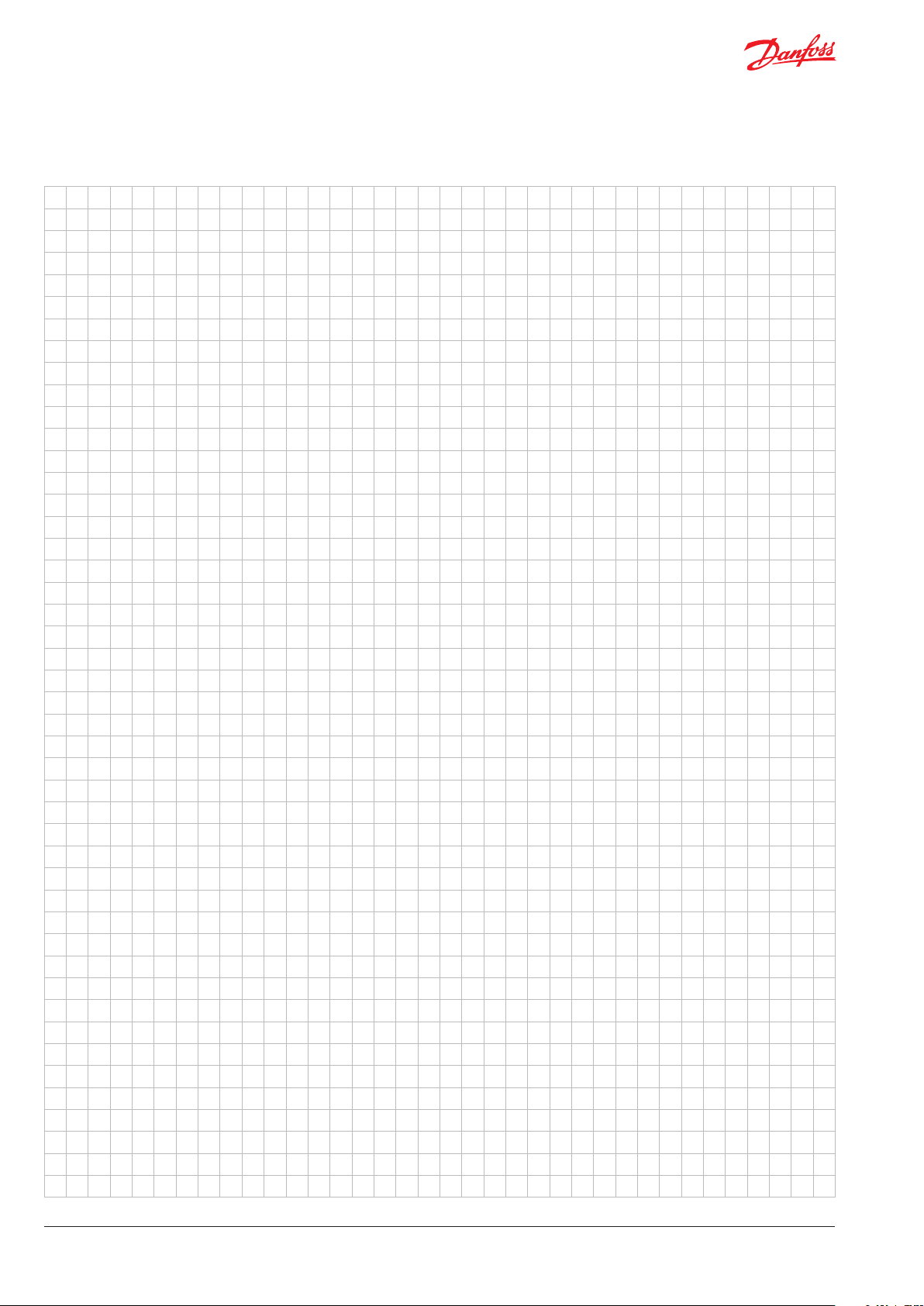
Equipment con guration Danfoss condensing units are delivered with a
compressor and condenser mounted on rails
or a base plate. Terminal boxes are prewired. In
addition, stop valves, solder adaptors, collectors,
dual pressure switches and power cables with
3-pin grounded plugs complete the delivery kit.
Power supply and
electrical equipment
Condensing units with 1-cylinder compressors
(types TL, FR, NL, GS, SC and SC-TWIN)
These condensing units are equipped with
hermetic compressors and fans for 230 V 1-,
50 Hz power supply.
The compressors are equipped with an HST
starting device consisting of a starting relay
and a starting capacitor. The components can
also be delivered as spare parts.
The starting capacitor is designed for short
activation cycles (1.7% ED). In practice, this
means that the compressors can perform up
to 10 starts per hour with an activation duration of 6 seconds.
Please consult the corresponding Danfoss
documentation or the current price list for
details and ordering numbers. The Danfoss sales
company responsible for your area will be glad
to help you make your selection.
Condensing units with hermetic 1-2 and
4 cylinder Maneurop® reciprocating piston
compressors MTZ and NTZ.
These condensing units are equipped with
hermetic compressors and fan(s) for di erent
voltage supplies:
• 400 V-3ph-50 Hz for compressor and for
fan(s).
• 400 V-3ph-50Hz for compressor and
230 V-1ph-50Hz for fan(s) (the capacitor(s)
of the fans are included inside the electrical
box).
• 230 V-3ph-50Hz for compressor and
230 V-1ph-50Hz for fan(s) (the capacitor(s)
of the fans are included inside the electrical
box).
• 230 V-1ph-50Hz for compressor (the starting
device (capcitors, relay) is included into the
electrical box) and 230V-1ph-50Hz for fan(s)
Condensing
units
The starting current of the Maneurop® threephase compressor can be reduced through the
use of a soft starter. CI-tronic
TM
soft start, type
MCI-C is recommended for use with this type of
compressor. The starting current can be reduced
up to 40% depending on the compressor model
and the model of soft start used. The mechanical
load that occurs at start-up is also reduced,
which increases the lifespan of the internal
components.
For details on the CI-tronic
TM
MCI-C soft start,
please contact your local Danfoss dealer.
The number of compressor starts is limited
to 12 per hour in normal conditions. Pressure
equalisation is recommended when MCI-C is
used.
3DKRCC.PF.000.G3.02 / 520H6471
Page 4
Fitters’ Notes Condensing units
Hermetic compressors The hermetically sealed compressor types w,
FR, NL, GS, SC and SC TWIN have a built-in
winding protector. When the protector is
activated, a switch-o time of up to 45 minutes can
occur as the result of heat storage in the motor.
The single-phase Maneurop® compressors
MTZ and NTZ are internally protected by a
temperature/current sensing bimetallic protector,
which senses the main and start winding currents
and also the winding temperature.
The three-phase Maneurop® reciprocating piston
compressors MTZ and NTZ are equipped against
over-current and over-temperature by internal
motor protection. The motor protection is located
in the star point of the windings and opens all
3 phases simultaneously via a bimetallic disk.
After the compressor has switched o via the bimetallic disc, reactivation can take up to 3 hours.
Condensers and fans Highly eective condensers allow a broader
range of usage at higher ambient temperatures.
One or two fan motors are used per condensing
unit depending on the output value.
In addition, the fans can be equipped, e.g. with
a Danfoss Saginomiya fan speed regulator, type
RGE. This allows good condensing pressure
control and reduces the noise level. The fans
are provided with self-lubricating bearings,
which ensures many years of maintenance-free
operation.
If the motor does not work, you can determine by
means of resistance measurement whether the
cause is a switched o winding protection switch
or a possible broken winding.
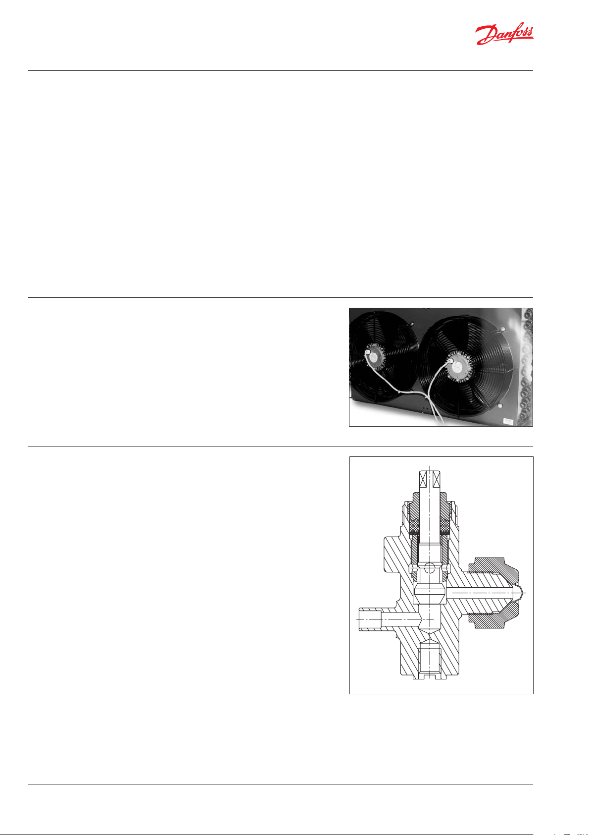
Stop valves Danfoss condensing units are provided with stop
valves on the suction and liquid side.
The stop valves of the condensing units with
the 1-cylinder compressors (types TL, FR, NL,
GS, SC and SC TWIN) are closed by turning the
spindle clockwise to te soldered piece. This opens
the ow between the pressure gauge connection
and the are connection. If you turn the spindle
counter-clockwise to the rear stop, the pressure
gauge connection is closed. The ow between
the soldered and the are connection is free. In
the centre position, the ow through the three
connections is free. The accompanying soldered
adapters help prevent are connections and to
make the system hermetic.
The stop valves of the condensing units with
Maneurop® reciprocating piston compressors
MTZ and NTZ are directly tted into the suction
and discharge rotalock ports of the compressor
and on the receiver. The suction valve is provided
with long, straight tube pieces in such a manner
that soldered connections can be carried out
without disassembling the Rotalock valve.
4 DKRCC.PF.000.G3.02 / 520H6471
Page 5
Fitters’ Notes Condensing units
Receiver Liquid receiver is standard on Danfoss
condensing units for use with expansion valves.
The expansion valve is regulating the level in
the receiver buer (the de- or increasing ow
of the refrigerant). The receivers from an internal
volume of 3 l onwards are equipped with a
Rotolock Valve.
Terminal box The Danfoss condensing units are electrically
pre-wired and equipped with a terminal box.
Thus the power supply and additional electrical
wiring can be easily tted. The terminal box of
the condensing units with Maneurop®
compressors is equipped with screw type
connector blocks for both power and controls.
Safety pressure monitors Danfoss condensing units can be ordered
with safety pressure switches KP 17 (W, B…).
Condensing units that do not come equipped
with pressure switches from the factory must
be equipped with a pressure switch at least
the high-pressure side in systems with
thermostatic expansion valves as per EN 378.
The electrical connections of each component
(compressor, fan(s), PTC, pressure switch) are
centralised into this box. A wiring diagram is
available in the cover of the electrical box.
These terminal boxes are protected to a degree
of IP 54.
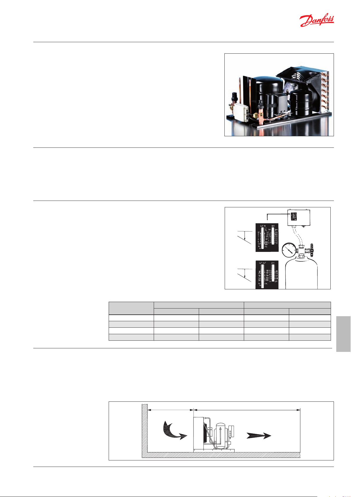
LP
Start
Stop
AB
Diff.
Setup
HP
Stop
Start
AB
Diff.
The following settings are recommended:
Refrigerant Low pressure side High pressure side
Cut in (bar) Cut o (bar) Cut in (bar) Cut o (bar)
R407C 2 1 21 25
R404A/R507 MBP 1.2 0.5 24 28
R404A/R507 LBP 1 0.1 24 28
R134a 1.2 0.4 14 18
Danfoss condensing units must be set up in a
well ventilated location.
You must ensure that there is sucient fresh air
for the condenser at the intake end.
In addition, you must ensure that no cross-ow
The ventilator motor is connected in such a way
that the air is drawn in via the condenser in the
direction of the compressor.
For optimal operation of the condensing unit,
the condenser must be cleaned regularly.
occurs between the fresh air and the exhaust air.
Condensing
units
5DKRCC.PF.000.G3.02 / 520H6471
Page 6
Fitters’ Notes Condensing units
Protective weather-proof
housing
Careful installation
Contamination and
foreign particles
Danfoss condensing units that are set up
outside must be provided with a protective
roof or with protective weather-resistant
housing. The scope of delivery includes
optional, high-quality protective weatherproof housings.
More and more commercial cooling and
air-conditioning systems are installed with
condensing units that are equipped with
Contamination and foreign particles are among
the most frequent causes that negatively impact
the reliability and lifespan of cooling systems.
During the installation, the following types of
contamination can enter the system:
Scaling during soldering (oxidations)
Flux residue from soldering
Humidity and outside gasses
Shavings and copper residues from deburring
the tubing
hermetic compressors. High demands are put
on the quality of the installation work and the
alignment of such a cooling system.
Doing the pipe work
Tubing layout of the
condensing units with
1-cylinder compressors
(types GS, TL, FR, NL, SC
and SC-TWIN)
For this reason, Danfoss recommends the
following precautions:
Use only clean and dry copper tubing and
components that satisfy standard DIN 8964.
Danfoss oers a comprehensive and integral
range of products for the necessary cooling
automation. Please contact your Danfoss
dealer for additional information.
When laying the tubing, you should try to make
the shortest and most compact pipe work
possible. Low-lying areas (oil traps), where oil
might accumulate should be avoided.
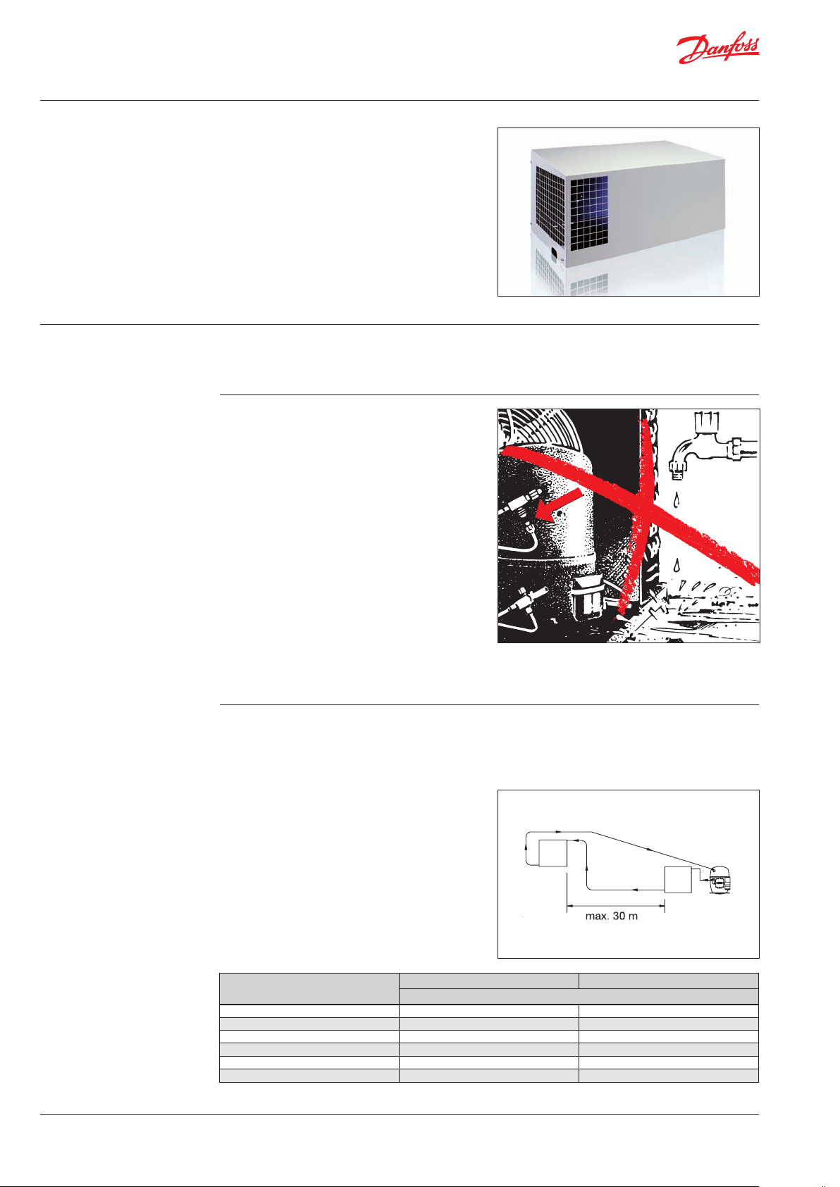
1. Condensing unit and evaporator are
located on the same level.
The suction line should be arranged slightly
downward from the compressor. The max.
permissible distance between the condensing
unit and the cooling position (evaporator) is
30 m.
TL 8 6
FR 10 6
NL 10 6
SC 10 8
GS 12/16 10
SC-TWIN 16 10
Evaporator
Suction Line Liquid Line
Diameter copper pipe [mm]
Condenser
Compressor
6 DKRCC.PF.000.G3.02 / 520H6471
Page 7
Fitters’ Notes Condensing units
Tubing layout of the
condensing units with
1-cylinder compressors
(types TL, FR, NL,SC, GS and
SC-TWIN) (continued)
To ensure the oil return, the following crosssections are recommended for the intake and
liquid lines:
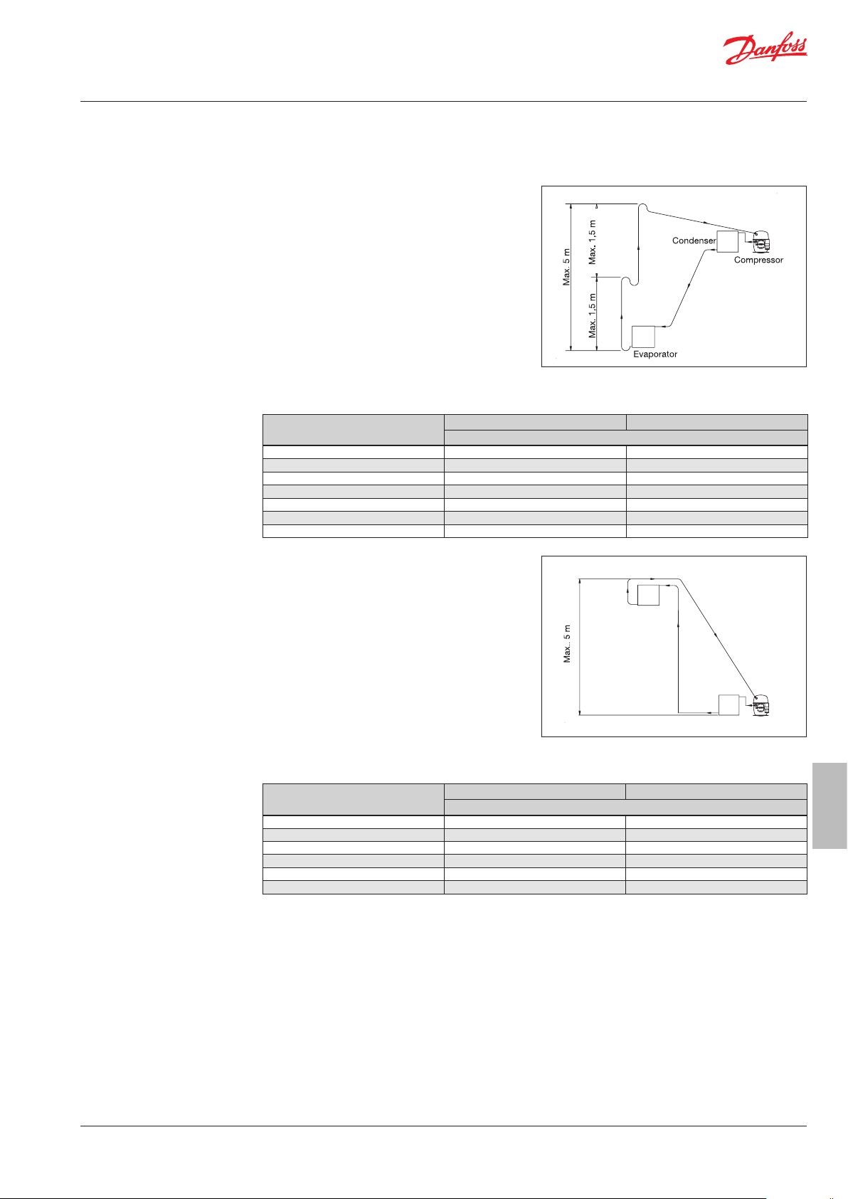
2. The condensing unit is arranged above the
evaporator.
The ideal height dierence between the
condensing unit and the evaporator position
is a max. of 5 m. The tube length between
the condensing unit and the evaporator
should not exceed 30 m. The suction lines
must be laid out with double arcs in the form
of oil traps above and below. This is done
using a U-shaped arc at the lower end and a
P-shaped arc at the upper end of the vertical
riser. The max. distance between the arcs is
1 to 1.5 m. To ensure the oil return, the
following pipe diameters are recommended
for the suction and liquid lines:
Suction Line Liquid Line
Diameter copper pipe [mm]
TL 8 6
FR 10 6
NL 10 6
SC 12/15 10 8
All other SCs 12 8
GS 16 10
SC TWIN 16 10
3. The condensing unit is arranged under the
evaporator.
The ideal height dierence between the
condensing unit and the evaporator is a max.
of 5 m. The tube length between the
Evaporator
condensing unit and the evaporator should
not exceed 30 m. The suction lines must be
laid out with double arcs in the form of oil
traps above and below. This is done using a
U-shaped arc at the lower end and a P-shaped
arc at the upper end of the vertical riser. The
max. distance between the arcs is 1 to 1.5 m.
To ensure the oil return, the following pipe
diameters are recommended for the suction
and liquid lines:
Suction Line Liquid Line
Diameter copper pipe [mm]
TL 8 6
FR 10 6
NL 10 6
SC 12 8
GS 16 10
SC TWIN 16 10
Condenser
Compressor
Condensing
units
7DKRCC.PF.000.G3.02 / 520H6471
Page 8

Fitters’ Notes Condensing units
Tubing layout of the
condensing
units with hermetic
Maneurop®
reciprocating piston
compressors,
1-2-4 cylinder
The tubes should be laid out to be exible
(dispersible in three planes or with “AnaConda”).
When laying the tubing, you should try to make
the shortest and most compact tubing network
possible.
Low-lying areas (oil traps), where oil might
accumulate should be avoided. Horizontal lines
should be laid inclined slightly downward toward
the compressor. To guarantee the oil return, the
suction speed at the risers must be at least
8-12 m/s.
For horizontal lines, the suction speed must
not fall below 4 m/s. The vertical suction lines
must be laid out with double arcs in the form of
oil traps above and below. This is done using a
U-shaped arc at the lower end and a P-shaped
arc at the upper end of the vertical tubing. The
maximum height of the riser is 4 m, unless a
second U-shaped arc is attached.
max. 4 m
max. 4 m
0.5 fall,
4 m/s or more
U shaped arc as short as possible
8 to 12 m/s
0.5 fall,
4 m/s or more
To condenser
U shaped arc
Evaporator
Leak check
If the evaporator is mounted above the
condensing unit, you must ensure that no liquid
refrigerant enters the compressor during the
work-stoppage phase. To avoid condensation
droplets from forming and to prevent an
unwanted rise of the intake gas over-heating,
the suction line must generally be insulated.
Adjusting the intake gas over-heating is done
individually for each use. You can nd more
detailed information in the following sections
under “max. permitted temperatures.“
Danfoss condensing units are checked in the
factory for leaks using helium. They are also
lled with a protective gas and must therefore
be evacuated from the system. In addition, the
added refrigerant circuit must be leak-checked
using nitrogen. The suction and liquid valves of
the condensing unit remain closed during this.
The use of coloured leak-checking agents will
void the warranty.
U shaped arc as short as possible
8 to 12 m/s at
lowest capacity
From evaporator
U shaped arc as short as possible
To compressor
8 to 12 m/s at
highest capacity
8 DKRCC.PF.000.G3.02 / 520H6471
Page 9

Fitters’ Notes Condensing units
Soldering The most common solders are alloys of
copper, zinc and tin. For “silver, copper“ (silver
content ~ 40 %) the melting point is between
approx. 655°C and 755°C. The coated silver
solder contains the ux needed for soldering.
This should be removed after soldering.
Silver solder can be used to solder together
various materials, e.g. steel/copper. Ag 15%
solder is su cient to solder copper to copper.
Protective gas
At the high soldering temperatures under the
in uence of ambient air, oxidation products form
(scaling).
The system must therefore have protective gas
owing through it when soldering. Supply a weak
stream of a dry, inactive gas through the tubes.
Only begin soldering when there is no
atmospheric air left in the a ected component.
Initiate the work procedure with a strong stream
of protective gas, which you can reduce to a
minimum when you start soldering.
This weak ow of protective gas must be
maintained during the entire soldering process.
The soldering must be done using nitrogen and
gas with a gentle ame. Only add the solder
when the melting point temperature has been
reached.
Fork burner:
Condensing
units
9DKRCC.PF.000.G3.02 / 520H6471
Page 10

Fitters’ Notes Condensing units
Evacuating and lling
The vacuum pump should be able to suction o
the system pressure to approx. 0.67 mbar, in two
stages if possible.
Humidity, ambient air and protective gas should
be removed. If possible, provide for a two-ended
evacuation, from the suction and the liquid side
of the condensing unit.
Use the connections at the suction and discharge
valves of the condensing units.
For lling the system, a lling level indicator,
lling cylinder and/or a scale is used for smaller
condensing units. The refrigerant can be fed into
the liquid line in the form of a liquid if a lling
valve is installed.
Otherwise, the refrigerant must be fed into the
system in gaseous form via the suction stop
valve while the compressor is running (break the
vacuum beforehand).
Please observe that the refrigerants R404A, R507
and R407C are mixtures.
The refrigerant manufacturers recommend lling
R507 as a liquid or gas, whereas R404A and
especially R407C should be lled in liquid form.
Therefore we must recommend that R404A, R507
and R407C are lled as described using a lling
valve.
If the amount of refrigerant to be lled is
unknown, continue lling until no bubbles
are visible in the inspection glass. During this,
you need to keep a constant watch on the
condensing and suction gas temperature in order
to guarantee normal operating temperatures.
Please observe the following procedures for
evacuating and lling the Danfoss condensing
units with the 1-cylinder compressors, types
TL, FR, NL, SC and SC TWIN.
For evacuating, both external hoses are connected
to a service battery aid and the condensing unit is
evacuated with stop-valves 1 and 2 open (spindle
in the center position).
After evacuation, both valves (4 and 5) are
connected to the service battery. Only then is the
vacuum pump switched o.
The refrigerant bottle is connected at the centre
connection of the service battery aid 3, and the
lling piece is briey vented.
The corresponding valve of service battery aid 4
is opened and the system is lled via the manometer connection of the suction stop valve with
the maximum allowable refrigerant operating
lling for a compressor that is in operation.
10 DKRCC.PF.000.G3.02 / 520H6471
Page 11

Fitters’ Notes Condensing units
Evacuating and lling
(continued)
Please observe the following recommendation
for evacuating and lling the Danfoss
condensing units with condensing units with
hermetic Maneurop® reciprocating piston
compressors MTZ and NTZ.
We recommend that you carry out the evacuation
as described in the following:
1. The service valves of the condensing unit
must be closed.
2. After the leak check, if possible, a two-ended
evacuation should be carried out using a
vacuum pump to 0.67 mbar (abs.)
It is recommended that you use coupling
lines with a large through-put and that you
connect them to the service valves.
3. Once a vacuum of 0.67 is reached, the system
is separated from the vacuum pump. During
the next 30 minutes, the system must not rise.
If the pressure rises quickly, the system has a
leak.
A new leak check and evacuation (after 1)
must be carried out. If the pressure rises
slowly, this is an indication that humidity
is present. If this is the case, perform a new
evacuation (after 3).
Exceeding the max.
allowable operational
lling capacity and
setting up outdoors
4. Open the service valves of the condensing
unit and break the vacuum with nitrogen.
Repeat procedures 2 and 3.
General information:
The compressor should only be switched on if the
vacuum has been broken.
For compressor operation with a vacuum in the
compressor housing, there is a risk of voltage
spark-over in the motor winding.
If the refrigerant is lled beyond the max.
allowable operational lling capacity or when
setting up outdoors, protective precautions
must be taken.
You can nd the max. allowable operational
lling capacities in the technical information
and/or installation instructions for the Danfoss
compressors. If there are any questions, your
local Danfoss sales company will be glad to
assist you.
One quick and easy solution for preventing
refrigerant displacements during the
shut-down phases is the use of a crankcase
heater.
Condensing
units
11DKRCC.PF.000.G3.02 / 520H6471
Page 12

Fitters’ Notes Condensing units
Exceeding the max.
allowable operational
lling capacity and
setting up outdoors
(continued)
For Danfoss condensing units that are
equipped with 1-cylinder compressors, types
TL, FR, NL, GS, SC and SC TWIN, following size
of crankcase heaters can be used:
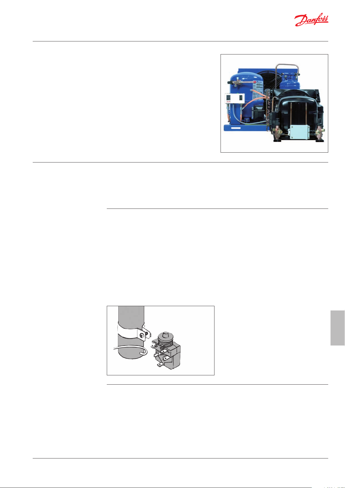
Crankcase heater for TL/FR/NL 35 W, order
no. 118U0050
Crankcase heater for GS, SC and SC-TWIN 55
W, order no. 118U0051
Housing heaters must be mounted directly
above the welded seam. For TWIN compressors,
both compressors must have a housing heater.
The electrical connection can be carried out as
follows:
For activated main switches, the change-over
contact of the regulating thermostat (e.g. KP 61)
takes over the switching function, i.e. compressor
o – heater on, and vice versa. The housing
heater should also be switched on approx. 2–3
hours before startup after a long down-time of
the cooling system.
For setting up the condensing units outdoors, it is
generally recommended to use housing heaters.
Please observe the following wiring recommendations.
The Danfoss condensing units with hermetic 1,
2 or 4-cylinder Maneurop® reciprocating piston
compressors MTZ and NTZ come standard
equipped with a self-regulating PTC 35 W
crankcase heater.
The self-regulating PTC heater protects against
refrigerant displacement during the shutdown
phase. However, reliable protection is only
aorded when the oil temperature is 10 K above
the saturation temperature of the refrigerant.
It is advisable to check by means of tests that a
sucient oil temperature is reached for both low
and high ambient temperatures.
For condensing units that are set up outdoors
and exposed to low ambient temperatures or
for cooling applications with larger amounts of
refrigerant, an additional belt crankcase heater is
often required for the compressor.
The heater should be mounted as close to the
oil sump as possible in order to ensure ecient
transfer of heat to the oil. Belt crankcase heaters
are not self-regulating.
The regulating is supposed to be achieved
by the heater being switched on when the
compressor is stopped and switched o when
the compressor is running.
These measures prevent the refrigerant from
condensing in the compressor. You must observe
that the crankcase heater is switched on at
least 12 hours prior to the compressor startup whenever the condensing units are being
restarted after a long down-time.
12 DKRCC.PF.000.G3.02 / 520H6471
Page 13

Fitters’ Notes Condensing units
“Pump-down“ If it is not possible to keep the oil temperature
at 10 K over the saturation temperature of the
refrigerant using the crankcase heater during
compressor down-time or when liquid refrigerant
ows back, a pump-down process on the low
pressure end must be used to prevent the further
possibility of refrigerant displacement during
shutdown phases.
The solenoid valve in the liquid line is controlled
by a thermostat. If the solenoid valve closes, the
compressor provides suction on the low pressure
end until the low pressure switch switches o the
compressor at the set switching point.
With “pump-down“, the activation point of the
low pressure switch must be set lower than
the saturation pressure of the refrigerant at the
lowest ambient temperature of the condensing
unit and the evaporator.
A liquid separator provides protection against
refrigerant displacement at the start-up, during
operation or after the hot gas defrosting process.
The liquid separator protects against refrigerant
displacement during the shut-down period while
the internal free volume of the suction end of the
system is increased.
The liquid separator should be laid out according
to the manufacturer’s recommendations.
As a rule, Danfoss recommends that the holding
capacity of the liquid separator not be less than
50% of the entire system’s lling capacity.
A liquid separator should not be used in systems
with zeotropic refrigerants such as R407C, for
example.
Condensing
units
13DKRCC.PF.000.G3.02 / 520H6471
Page 14

Fitters’ Notes Condensing units
Max. allowable
temperatures
For the Danfoss condensing units with
1-cylinder compressors (types TL, FR, NL, GS,
SC and SC TWIN), the evaporator superheat
(measured at the sensor of the expansion valve
meaning the temperature at pressure gauge)
should be between 5 and 12 K.
The max. return gas temperature is measured
at the compressor intake: 45°C. Impermissibly
high intake gas over-heating leads inevitably
to a quick rise in the discharge temperature.
This must not exceed 135°C for the SC compressor
and 130°C for the TL, NL and FR compressors.
The pressure tube temperature is measured
50 mm away from the pressure connector of the
compressor.
For condensing units with hermetic
Maneurop® reciprocating piston compressors
MTZ and NTZ, the evaporator superheat (E-valve
sensor) should be between 5 and 12 K.
The max. return gas temperature, measured at
the compressor suction connector is 30°C.
Impermissibly high intake gas superheat
inevitably leads to a rapid rise in the pressure gas
temperature, the maximum value of which must
not be exceeded (130°C).
For special applications (multi-evaporator systems),
the use of an oil separator is recommended in the
pressure line.
14 DKRCC.PF.000.G3.02 / 520H6471
Page 15

Fitters’ Notes Condensing units
Introduction These notes pertain to Danfoss packaged
condensing units used for refrigeration systems.
They provide necessary information regarding
safety and proper usage of this product.
The condensing unit includes following:
Microchannel condenser
(Optyma Plus™ New Generation &
Optyma™ Slim Pack)
Fin and tube condenser (Optyma Plus™)
Reciprocating or scroll compressor
Receiver with stop valve
Ball valves
Sight glass
High & low pressure switches
Filter drier
Electronic controller
(only Optyma Plus™ New Generation)
Main circuit breaker
(Main switch with overload protection)
Fan and compressor capacitors
Compressor contactor
Robust weather proof housing
Handling and storage Store and transport the unit in an upright
position.
15DKRCC.PF.000.G3.02 / 520H6471
Condensing
units
Page 16

Fitters’ Notes Condensing units
Installation precautions
Ensure adequate space around the unit for
air circulation and to open doors.
Avoid installing the unit in aggressive and
dusty environments.
Ensure a foundation with horizontal surface
(less than 3° slope), strong and stable
enough to carry the entire unit weight and
to eliminate vibrations and interference.
Ensure that the power supply corresponds
to the unit characteristics (see nameplate).
When installing units for HFC refrigerants,
use equipment specically reserved for
HFC refrigerants which was never used for
CFC or HCFC refrigerants.
Use clean and dehydrated refrigeration-
grade copper tubes and silver alloy brazing
material.
Use clean and dehydrated system compo-
nents.
The suction piping connected to the
compressor must be exible in 3 dimensions
to dampen vibrations. Furthermore piping
has to be done in such a way that oil return
for the compressor is ensured and the risk of
liquid slug over in compressor is eliminated.
Minimum mounting distances
Q W
R
Q: AIR in R: AIR inout
Unit
Housing 1
(Code n 114X31 -- or 114X41 - -)
Housing 2
(Code n 114X32 -- or 114X42 --)
Housing 3
(Code n 114X33 -- or 114X43 --)
Housing 4
(Code n 114X31 -- or 114X41 --)
Remove cap and access cap
X
W
(mm)X(mm)Y(mm)Z(mm)
250 550 456 456
250 650 530 530
250 760 581 581
250 900 700 700
OPEN position
16 DKRCC.PF.000.G3.02 / 520H6471
Page 17

Fitters’ Notes Condensing units
Installation The installation in which the condensing
unit is installed must comply to EEC Pressure
directive (PED) nr. 97/23/EC.
The condensing unit itself is not a ”unit” in
the scope this directive.
It is recommended to install the unit on
rubber grommets or vibration dampers
(not supplied).
It is possible to stack units on top of each
other (only Optyma Plus™ New Generation).
Unit maximum stacking
Housing 1
(Code no. 114X31-- or 114X41--) 3
Housing 2
(Code no. 114X32-- or 114X42--) 2
Housing 3
(Code no. 114X33-- or 114X43--) 2
Housing 4
(Code no. 114X34-- or 114X44--) no stacking
When stacking, the topmost unit must be
secured to the wall.
Slowly release the nitrogen holding charge
through the schrader port.
Connect the unit to the system as soon
as possible to avoid oil contamination from
ambient moisture.
Avoid material entering into the system
while cutting tubes. Never drill holes where
burrs cannot be removed.
Braze with great care using state-of-the-art
technique and vent piping with nitrogen gas
ow.
Connect the required safety and control
devices. When the schrader port is used for
this, remove the internal valve.
It is recommended to insulate the suction
pipe up to the compressor inlet with 19 mm
thick insulation.
17DKRCC.PF.000.G3.02 / 520H6471
Condensing
units
Page 18

Fitters’ Notes Condensing units
Leak detection
Vacuum dehydration Never use the compressor to evacuate the
Electrical connections Switch o and isolate the main power supply.
Never pressurize the circuit with oxygen or
dry air. This could cause re or explosion.
Do not use dye for leak detection
Perform a leak detection test on the
complete system
The maximum test pressure is 32 bar.
When a leak is discovered, repair the leak
and repeat the leak detection.
system Connect a vacuum pump to both the
LP & HP sides.
Pull down the system under a vacuum of
500 m Hg (0.67 mbar) absolute.
Do not use a megaohmmeter nor apply
power to the compressor while it is
under vacuum as this may cause internal
damage.
Ensure that power supply can not be switched
on during installation.
All electrical components must be selected as
per local standards and unit requirements.
Refer to wiring diagram for electrical connec-
tions details.
Ensure that the power supply corresponds to
the unit characteristics and that the power
supply is stable (nominal voltage ±10% and
nominal frequency ±2,5 Hz)
Dimension the power supply cables according
to unit data for voltage and current.
Protect the power supply and ensure correct
earthing.
Make the power supply according to local
standards and legal requirements
Optyma Plus™ New Generation is equipped
with an electronic controller. The controller is
regulating fan speed and crankcase heater.
The unit is equipped with a main switch with
overload protection. The overload protection is
factory preset but it is recommended to check
the value before taking the unit in operation.
The value for the overload protection can be
found in the wiring diagram in the front door
of the unit.
The unit is equipped with high and low pres-
sure switches, which directly cut the power
supply to the compressor in case of activation.
Parameters for high and low pressure cut outs
are preset in the controller, adapted to the
compressor installed in the unit (Optyma Plus™
New Generation)
For units with a 3-phase scroll compressor
(OPMPUxxxxxxxxE), correct phase sequence
for compressor rotation direction shall be
observed.
Determine the phase sequence by using a
phase meter in order to establish the phase
orders of line phases L1, L2 and L3.
Connect line phases L1, L2 and L3 to main
switch terminals T1, T2 and T3 respectively.
18 DKRCC.PF.000.G3.02 / 520H6471
Page 19

Fitters’ Notes Condensing units
Filling the system
Setting the electronic
controller
(only Optyma Plus™ New
Generation)
Never start the compressor under vacuum.
Keep the compressor switched o .
Use only the refrigerant for which the unit
is designed for.
Fill the refrigerant in liquid phase into the
condenser or liquid receiver. Ensure a slow
charging of the system to 4 – 5 bar for
R404A and approx. 2 bar for R134a.
The remaining charge is done until the
installation has reached a level of stable
nominal condition during operation.
Never leave the lling cylinder connected
to the circuit.
The unit is equipped with an electronic
controller which is factory programmed with
parameters for use with the actual unit.
By default, the electronic controller display
shows the temperature value for the suction
pressure in °C. To show the temperature
value for the condensing pressure, push the
lower button.
The electronic controller is factory preset for
operation with refrigerant R404A. If another
refrigerant is used, the refrigerant setting
must be changed. Parameter r12 must be set
to 0 before (software main switch = o ).
Push the upper button for a couple of seconds.
The column with parameter codes appears.
Push the upper or lower button to nd
parameter code o30.
Push the middle button until the value for this
parameter is shown.
Push the upper or lower button to select the
new value: 2 = R22, 3 = R134a, 13 = User
de ned, 17 = R507, 19 = R404A, 20 = R407C.
Push the middle button to con rm the selected
value.
19DKRCC.PF.000.G3.02 / 520H6471
Condensing
units
Page 20

Fitters’ Notes Condensing units
Verication before
commissioning
Start-up Never start the unit when no refrigerant is
Use safety devices such as safety pressure
switch and mechanical relief valve in
compliance with both generally and locally
applicable regulations and safety standards.
Ensure that they are operational and properly
set. Check that the settings of high-pressure
switches and relief valves don’t exceed the
maximum service pressure of any system
component.
Verify that all electrical connections are
properly fastened and in compliance with
local regulations.
When a crankcase heater is required, the
unit must be energized at least 12 hours
before initial start-up and start-up
after prolonged shutdown for belt type
crankcase heaters.
The unit is equipped with a main switch
with overload protection. Overload
protection is preset from factory, but it
is recommended to check the value
before taking the unit in operation.
The overload protection value can be
found in the wiring diagram in the unit
front door.
charged.
All service valves must be in the open
position.
Check compliance between unit and power
supply.
Check that the crankcase heater is working.
Check that the fan can rotate freely.
Check that the protection sheet has been
removed from the backside of condenser.
Balance the HP/LP pressure.
Energize the unit. It must start promptly.
If the compressor does not start, check
wiring conformity and voltage on
terminals.
Optimum
Location
Area
p
c
Eventual reverse rotation of a 3-phase
compressor can be detected by following
phenomena; the compressor doesn’t
build up pressure, it has abnormally high
sound level and abnormally low power
consumption. In such case, shut down the
Only for scroll compressors:
20 DKRCC.PF.000.G3.02 / 520H6471
unit immediately and connect the phases
to their proper terminals.
If the rotation direction is correct the low
pressure indication on the controller
(or low pressure gauge) shall show a
declining pressure and the high pressure
indication (or high pressure gauge) shall
show an increasing pressure.
po < p
p
o
c
Page 21

Fitters’ Notes Condensing units
Check with running unit
Check the fan rotation direction. Air must ow
from the condenser towards the fan.
Check current draw and voltage.
Check suction superheat to reduce risk of
slugging.
When a sight glass is provided observe the oil
level at start and during operation to conrm
that the oil level remains visible.
Respect the operating limits.
Check all tubes for abnormal vibration. Move-
ments in excess of 1.5 mm require corrective
measures such as tube brackets.
When needed, additional refrigerant in liquid
phase may be added in the low-pressure side
as far as possible from the compressor. The
compressor must be operating during this
process.
Do not overcharge the system.
Never release refrigerant to atmosphere.
Before leaving the installation site, carry out
a general installation inspection regarding
cleanliness, noise and leak detection.
Record type and amount of refrigerant charge
as well as operating conditions as a reference
for future inspections.
Maintenance part 1 Always switch o the unit at main switch before
opening the fan door (s).
Internal pressure and surface temperature
are dangerous and may cause permanent injury.
Maintenance operators and installers require
appropriate skills and tools. Tubing temperature
may exceed 100°C and can cause severe burns.
Ensure that periodic service inspections to
ensure system reliability and as required by local
regulations are performed.
To prevent system related problems, following
periodic maintenance is recommended:
Verify that safety devices are operational and
properly set.
Ensure that the system is leak tight.
Check the compressor current draw.
Conrm that the system is operating in a way
consistent with previous maintenance records
and ambient conditions.
Check that all electrical connections are still
adequately fastened.
Condensing
units
21DKRCC.PF.000.G3.02 / 520H6471
Page 22

Fitters’ Notes Condensing units
Maintenance part 2 Keep the unit clean and verify the absence of
rust and oxidation on the unit components,
tubes and electrical connections.
The condenser must be checked at least once
a year for clogging and be cleaned if deemed
necessary. Access to the internal side of the
condenser takes place through the fan door
or fan panel. Microchannel coils tend to
accumulate dirt on the surface rather than
inside, which makes them easier to clean than
n-&-tube coils.
Switch o the unit at main switch before
opening the fan door or removing fan panel.
Remove surface dirt, leaves, bres, etc. with
a vacuum cleaner, equipped with a brush
or other soft attachment. Alternatively, blow
compressed air through the coil from the
inside out (only at Microchannel condensers –
at n and tube condensers blow according to
the original air ow direction), and brush
with a soft bristle.
Do not use a wire brush. Do not impact or
scrape the coil with the vacuum tube or air
nozzle.
Before closing the fan door, turn the fan
blade in the right position to avoid that the
door hits the fan.
If the refrigerant system has been opened,
the system has to be ushed with dry air or
nitrogen to remove moisture and a new
lter drier has to be installed. If evacuation
of refrigerant has to be done, it shall be
done in such a way that no refrigerant can
escape to the environment.
22 DKRCC.PF.000.G3.02 / 520H6471
 Loading...