

Page 1
Compressor Drives
Troubleshooting Check List
CDS 302/CDS 303
http://cc.danfoss.com
Page 2

Page 3

Check List
Content
Introduction ......................................................................................................................................... 4
For Your Safety ..................................................................................................................................... 5
Diagnostics...........................................................................................................................................6
Initial Trouble Shooting (visual inspection of the installation) ....................................................... 7
Input power wiring ................................................................................................................................................................................... 7
Output to motor ........................................................................................................................................................................................ 7
Grounding .................................................................................................................................................................................................... 7
Control wiring ............................................................................................................................................................................................. 7
Programming .............................................................................................................................................................................................. 7
Compressor Motor .................................................................................................................................................................................... 7
Cable routing .............................................................................................................................................................................................. 7
Peripheral equipment (sensors, contactors, etc) ............................................................................................................................7
Trip on over Temperature ....................................................................................................................................................................... 7
Drive interior ............................................................................................................................................................................................... 7
EMC Precautions ........................................................................................................................................................................................ 7
Vibration ....................................................................................................................................................................................................... 7
Environmental conditions ...................................................................................................................................................................... 7
Proper clearance ........................................................................................................................................................................................ 7
Trouble shooting ................................................................................................................................8
Fault Symptoms - Display of the drive .............................................................................................................................................. 8
No display (blank display) ...................................................................................................................................................................... 8
Intermittent display .................................................................................................................................................................................. 8
Fault Symptoms in the compressor (motor) ....................................................................................................................................9
Common drives and motor problems ..............................................................................................11
Control logic problems ..........................................................................................................................................................................11
Programming problems ........................................................................................................................................................................11
IGBT, Motor or load problems ............................................................................................................................................................12
Procedure to conduct the dynamic test to check the IGBT .....................................................................................................12
Faults in the drive ....................................................................................................................................................................................12
EMC - Electro Magnetic Compatibility .............................................................................................................................................13
Static test procedures .......................................................................................................................14
Rectier test (static) ................................................................................................................................................................................14
IGBT static test ..........................................................................................................................................................................................15
3FRCC.PC.036.A2.02
Page 4
Check List
Introduction
Many frequency converters that are sent back
to Danfoss every year for factory analysis
are diagnosed with No Fault Found (NFF).
Establishing whether a frequency converter is
faulty or not prior returning it to the factory can
increase the uptime of the compressor solution,
reduce the unnecessary use of resources and
limit the number of NFF.
The purpose of this check list is to facilitate
users, eld technicians, engineers and service
personnel working with Danfoss frequency
converters to identify faults and perform a
rst diagnosis on the drive before sending it to
inspection and analysis.
PERFORM THE FOLLOWING FAULT DIAGNOSIS
BEFORE RETURNING A FREQUENCY CONVERTER FOR
FACTORY INSPECTION.
CHECK ALL POSSIBILITIES.
IN CASE OF DOUBT, PLEASE SEEK DANFOSS SUPPORT.
4 FRCC.PC.036.A2.02
Page 5
Check List
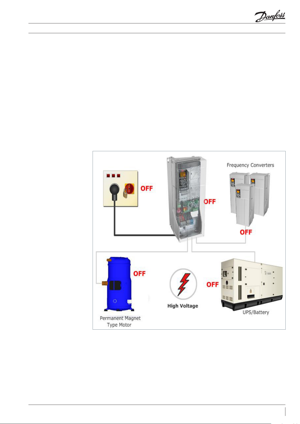
For Your Safety
Figure 1: Drive must be
turned OFF for 20min before
repair can start
Frequency Converters (FC) contain dangerous
voltages when connected to the line voltage.
Only a competent technician should carry out
the service.
Some instructions should be compulsorily
followed to ensure safety while working with the
FC.
• Do not touch electrical parts of the FC when the
AC line is connected.
• Frequency converters contain DC-link capacitors
that can remain charged even when the
frequency converter is not powered. To avoid
electrical hazards, disconnect AC mains, any
permanent magnet type motors, and any
remote DC-link power supplies, including
battery backups, UPS and DC-link connections
to other frequency converters.
• Wait for at least 20 minutes before touching any
of the components.
• When repair or inspection is done, the AC line
must be disconnected.
• The STOP key on the control panel does not
disconnect the AC line.
• During operation and programming of the
parameters, the motor may start without
warning. So you have to activate the STOP key
when changing data.
5FRCC.PC.036.A2.02
Page 6
Check List
Diagnostics
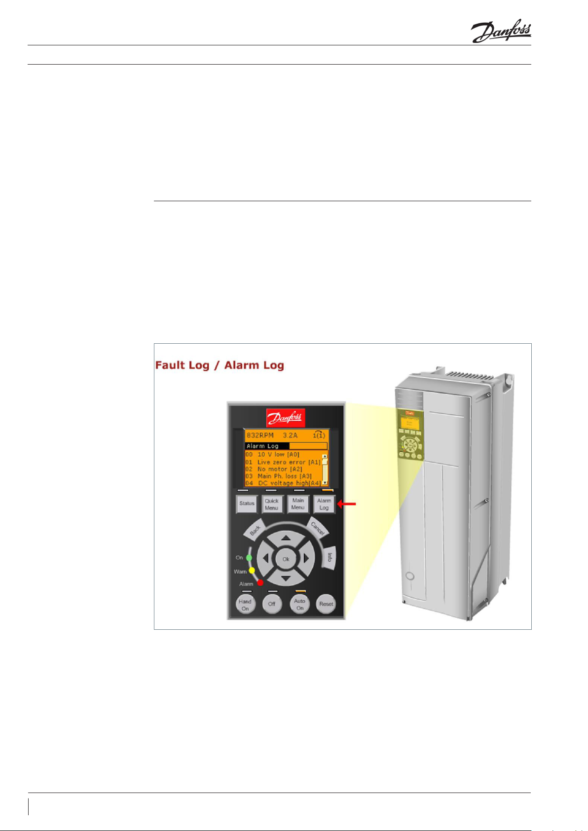
WARNINGS and ALARM
Fault detection via LCP: messages are displayed
when the frequency converter fault circuit
detects a faulty condition or an unresolved fault.
A warning light ashing display indicates
potential problems.
There are two levels of alarms; Reset Alarms and
Trip-lock Alarms.
Alarm Log Check the content of the alarm log.
5 latest alarms are available through the “Alarm
Log” button key on the LCP.
Check the alarm code and refer to the
troubleshooting session of the Operating
Instructions VLT® CDS 302 and CDS 303 on page
135. It contains guidance for the complete list
of alarms and warnings.
Figure 2: WARNINGS
and ALARM messages
are displayed when the
frequency converter fault
detects a faulty condition
a) In case of reset alarm: you can stop and then
start the unit.
b) In case of trip-lock alarm, you have to
disconnect the mains, wait for dark display,
then stop and start.
If the troubleshooting suggested does not
resolve the problem, please contact Danfoss for
support.
Do not exchange the drive before contacting
Danfoss support.
6 FRCC.PC.036.A2.02
Page 7

Check List
Initial Trouble Shooting (visual inspection of the installation)
Input power wiring
Output to motor
Grounding
Control wiring
Programming
Compressor Motor
This list shows a variety of conditions that
should be inspected visually as a part of initial
troubleshooting.
Check for loose connections. Check for proper fusing. Check for blown fuses.
Check for loose connections. Check for switching
components in the output circuit. Check for
faulty contacts in the switch gear.
The drive requires a dedicated ground wire
from its chassis to the building ground. It is also
suggested that the motor be grounded to the
drive chassis. The use of conduit or mounting
Check for broken or damaged wires and
connections. Check the voltage source of the
signals. Though not always necessary depending
Check that the drive parameter settings are
correct according to the motor, application and
I/O conguration.
Check nameplate of the Compressor. Ensure the
compressor matches the drive. Check that drive’s
Display: Warnings, alarms, drive status; fault
history and many other items are available on the
local control panel of the drive.
of the drive to a metal surface is not considered
a suitable ground. Check for good grounding
connections that are tight and free of oxidation.
on the installation condition, the use of shield
cable or a twisted pair is recommended. Ensure
the shield is terminated correctly.
compressor par. 1-13 is set according to the
compressor e.g.:
Cable routing
Peripheral equipment
(sensors, contactors, etc)
Trip on over Temperature
Drive interior
EMC Precautions
ID Name Setup 1 Factory Setup Unit
113 Compressor Selection VZH117-R410A VZH117-R410A
Avoid routing motor wiring. AC line wiring and
signal wiring in parallel. If parallel routing is
unavailable, try to maintain a separation of 15-
Look for peripheral equipment such as switches
or input fuses circuit breakers that may be in the
input power side of the drive or output side of
the motor. Examine operation and condition of
Check the operational status of all cooling fans.
Check for blockage or constrained air passages.
Drive interior must be free of dirt, metal, chips,
moisture and corrosion. Check for burnt or
damaged power components or carbon deposits
that were the result of a disastrous component
Check for proper installation with regards to
electromagnetic capability. Refer to the CDS
manual, in the chapter “How to install” and then
20cm between the cables or separate them with
a grounded conductive partition. Avoid routing
cables through free air.
these items as possible causes for operational
faults. Check function and installation of pressure
sensors or temperature sensors etc. used for
feedback to the drive.
failure. Check for cracks or breaks in the housing
of the power semiconductors or pieces of broken
components housing loose inside the unit.
“ Electrical Installation – EMC Protection “ for
further details.
Vibration
Environmental conditions
Proper clearance
Look for unusual amounts of vibration to which
the drive may be subject. The drive should be
Under specic conditions these units can
be operated within a maximum ambient
temperature of 50°C (24h average maximum
These drives require a top and bottom clearance
of 10cm to ensure proper airow for cooling.
mounted solidly or the use of shock mounts
employed.
45 °C). Humidity level must be less than 95%
non-condensing. Check for harmful airborne
contaminates such as sulphur based compounds.
Drives with exposed heat sinks out the back of
the drive must be mounted on a at solid surface.
7FRCC.PC.036.A2.02
Page 8

Check List
Trouble shooting
Fault Symptoms - Display
of the drive
No display (blank display)
Figure 3: No Display in the
LCP (blank)
A fault must have been ocurred when there is:
a) No Display in the LCP (blank)
b) Intermittent display in the LCP
There are three LED indicators lights near the
bottom of the LCP.
If the green power on LED is illuminated but the
backlit display is dark, this indicates that the LCP
itself is defective and must be replaced.
It should be certain that the display is completely
dark. An error code exists in the drive which
indicates that communications may have failed
with the control card.
This is typically seen when an option card has
been installed in the drive and is either not
connected properly or is malfunctioning.
• If neither indication is available, then the
source of the problem may be elsewhere.
Intermittent display
Figure 4: intermittent
display
8 FRCC.PC.036.A2.02
Cutting out or ashing of the entire display and
power LED indicates that the power supply
(SMPS) is shutting down as a result of being
overloaded.
This may be due to improper control wiring or a
fault within the drive itself.
Page 9

Check List
Figure 5: Check control
cables
Trouble shooting
• The rst step is to rule out the problem in the control wiring.
Figure 6: Disconnect all
control wiring
Fault Symptoms in the
compressor (motor):
Motor will not run
• Disconnect all control wiring by unplugging the
control terminal blocks from the control card.
All control wiring should be checked for shorts
or incorrect connections.
• First verify that the unit is properly powered up
and there is no warning or alarm .
• The most common cause of this is either
incorrect control logic or an incorrectly
programmed drive.
• If the display stays lit then the problem is in the
control wiring.
• If the display continues to cut out, the fault
can be located in either the LCP itself or on
the Power card.
Such occurrences will result in one or more of the
following status messages being displayed:
LCP Stop
Figure 7: LCP stop = OFF key
pressed
Stand by (gure 8)
The LCP stop message is displayed when the OFF
key has been pressed.
The stand by message is displayed when there is
no start signal at terminal 18.
The bottom section of the display will also be
ashing when this occurs.
Ensure that a start command is present at
terminal 18.
9FRCC.PC.036.A2.02
Page 10

Check List
Trouble shooting
Stop (gure 9)
Figure 9: Check pressure
switch
Run OK: 25Hz
Quick tip:
Message displayed when the Terminal 27 is low
(no signal).
The RUN OK status display indicates that a run
command has been given to the drive but the
reference (speed command) is zero or missing.
Improperly connected wiring or interrupted
wiring is a common service issue for a motor
Ensure that terminal 27 is logic 1 (pressure
switch).
Check the control wiring to ensure that a
proper reference signal is present at the drive
input terminals and that the unit is properly
programmed to accept the signal provided.
not operating or the drive not responding to a
remote input.
10 FRCC.PC.036.A2.02
Page 11

Check List
Common drives and motor problems
Control logic problems
Figure 10: checking control
signal in the control card
The common drives and motor problems occur
due to an error in the
• Control logic
• Programming
Control logic problem occurs when the drive
does not respond to a given command.
Control logic problem is located by using the
status information displayed by the drive.
Correct reading indicates that the desired signal
is detected by the microprocessor of the drive.
• Motor/load
• Internal drive
If there is not a correct indication, the next step is
to determine whether the signal is present at the
control terminals of the drive.
This can be performed with a voltmeter or
oscilloscope.
Programming problems
• If the signal is present at the terminal,
the control card is defective and must be
replaced.
• If the signal is not present, the problem is
external to the drive.
Three areas where programming errors may
aect the drive and motor operation are
motor settings, references and limits, and I/O
conguration.
The drives must be set up correctly for the
compressors connected to it. If not, the
compressor may fail to start or use higher than
normal amount of current.
Check if the correct compressor is selected in
pa r. 1-13.
The circuitry providing the signal along with its
associated wiring must then be checked.
Any references or limits set incorrectly will result
in less than acceptable drive performance.
In case of doubt, reset the drive to factory
settings using par. 14-22.
Download again the OEM settings using the
copy and paste function in par. 0-50.
11FRCC.PC.036.A2.02
Page 12

Check List
Common drives and motor problems
IGBT, Motor or load
problems
Procedure to conduct the
dynamic test to check the
IGBT
The motor or motor wiring can develop a phase
to phase or phase to ground short resulting in
alarm indication and a trip of the unit.
A motor with the unbalanced or nonsymmetrical impedances on all the three phases
can result in uneven or rough operation or
unbalanced output current.
• To determine whether the problem is internal
or external to the drive, disconnect the motor
from the drive output terminals.
Dynamic tests have to be done without the
compressor connected to UVW connector, and
the Drive has to be programmed to a proxy 50Hz
at start.
The Dynamic test can indicate if one of the IGBT
doesn’t switch, and the output voltage will drop
on the fault terminal, UVW.
Program the multimeter to AC 1000V RM.
• Connect the positive terminal of the multimeter
lead to the U connector, and connect the
negative terminal to the V terminal.
• Perform the dynamic output test procedure on
all three phases with a digital voltmeter.
• If the three voltage measurements are
balanced, the drive is functioning correctly.
The problem is therefore external to the drive.
• If the voltage measurements are not
balanced, the drive is malfunctioning.
This typically means that one or more output
IGBT is not switching on and o correctly.
If one of the IGBT fails, the drive is damaged
and must be replaced.
• Connect the positive terminal of the multimeter
lead to the U connector, and connect the
negative terminal to the W terminal.
• Connect the positive terminal of the multimeter
lead to the V connector, and connect the
negative terminal to the W terminal.
The meter reading will be between 360V - 380V
when performing the dynamic test at 400V
mains and 50Hz/3000RPM output depending on
instrument used.
The reading should be within ±1.5 percent. When
the reading exceeds this, the IGBT is damaged.
Figure 11: Dynamic test
Faults in the drive
Drive temperature sensor /
Over temperature fault
Current sensor fault
• If the drive is stopped and cooled, the LCP
reading shall show the ambient temperature.
When a current sensor fails, it is indicated
sometimes by an earth fault alarm that cannot be
reset, even with the motor leads disconnected.
• Disconnect the motor from the drive, and then
observe the current in the display of the drive.
Note: Both faults above are non-reparable. Drive needs to be replaced
• If not, the temperature sensor or temperature
measurement circuit is defective.
• If the motor is disconnected from the unit, the
LCP shall read out 0.00A.
• If anything else is shown, this indicates a
defective current sensor.
12 FRCC.PC.036.A2.02
Page 13

Check List
EMC - Electro Magnetic
Compatibility
Common drives and motor problems
Eects of EMI
Sources of EMI
Electro Magnetic compliance or EMC are the
voltage and current which are not sinusoidal but
pulsating.
Electromagnetic Compatibility (EMC) concerns
for typical commercial and industrial equipment.
EMI related disturbances to drive operation are
uncommon, but the following detrimental EMI
eects may be seen:
• Motor speed uctuations
• Serial communication transmission errors
• Drive CPU exception faults
• Unexplained drive trips
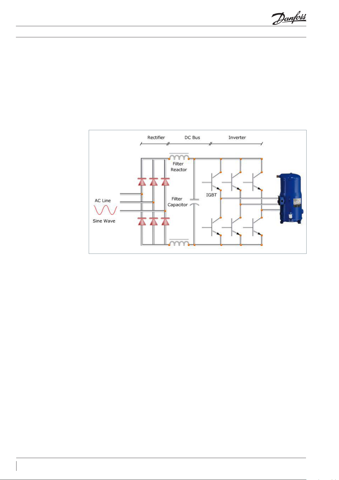
Drives utilize Insulated-Gate Bipolar Transistors
(IGBTs) to provide an ecient and cost eective
means to create the Pulse Width Modulated
(PWM) output waveform necessary for accurate
motor control.
Detrimental Eects To These Systems May
Include The Following:
• Pressure/ow/temperature signal transmitter
signal distortion or aberrant behaviour
• Radio and TV interference
• Telephone interference
• Computer network data loss
• Digital control system faults
These devices rapidly switch the xed DC bus
vo ltage creating a variable frequency, variable
voltage PWM waveform.
This high rate of voltage change [dV/dt] is the
primary source of the drive generated EMI.
13FRCC.PC.036.A2.02
Page 14

Check List
Static test procedures
Rectier test (static)
Symptom:
Step 1
Figure 12: Multimeter
should read a voltage drop
of 0,4V
Step 2
POWER MUST BE OFF / MAINS AND MOTOR
CABLES DISCONECTED!
Verication of: Rectier (input, mains) / IGBT
(Output, motor)
Failure of the rectier module will usually result
in blown input line fuses.
• Connect the negative terminal of the
multimeter meter lead to the positive DC bus.
• Connect the positive terminal of the multimeter
lead to the input terminal L1,L2,L3 in turn.
Now reverse the meter leads, i.e. connect
the positive terminal of the meter lead to the
positive DC bus.
• If rectier or IGBT fail, the complete power
card has to be exchanged, since in the CDS
drives, the rectier and IGBT are integrated in
one power card.
Procedure to conduct the static test on rectier:
• The multimeter should show the diode drop
of around 0.44 volt on the three terminals.
• Connect the negative terminal of the meter
lead to the input terminals L1, L2, L3 in turn.
• The multimeter should show diode open.
Figure 13: Multimeter
should show diode open
Step 3
Figure 14: Multimeter
should show a diode drop
of 0,44V
Now repeat the procedure by connecting to the
negative DC bus in order to the test the lower
part of the rectier bridge which consist of
diodes
• Connect the negative terminal of the meter
lead to the input terminals L1, L2, L3 in turn.
• The multimeter should show the diode drop
of around 0.44 volt on the three terminals.
14 FRCC.PC.036.A2.02
Page 15

Check List
Static test procedures
Step 4 Now reverse the meter leads, i.e. connect the
negative terminal of the meter lead to the
negative DC bus.
Figure 15: The multimeter
should show diode open
Note: A diode drop reading will vary depending on the model of the ohm meter
IGBT static test IGBT's are placed on the output of the CDS drives
Step 1
Figure 16: The multimeter
should show diode open
• Connect the positive terminal of the multimeter
lead to the positive DC bus.
• Connect the positive terminal of the meter lead
to the input terminals L1, L2, L3 in turn.
• The multimeter should show diode open.
• Connect the negative terminal of the
multimeter lead to the motor terminal U, V, W
in turn.
• The multimeter should show the diode open.
Step 2
Figure 17: The multimeter
should show the diode drop
of around 0.4 volt on the
three terminals
Step 3
Figure 18: The multimeter
should show open diode
Now reverse the meter leads, i.e. connect the
negative terminal of the meter lead to the
positive DC bus.
Now repeat the procedure by connecting to the
negative DC bus in order to test the second set
of IGBTs.
• Connect the positive terminal of the meter lead
to the motor terminals U, V, W in turn.
• The multimeter should show the diode drop
of around 0.4 volt on the three terminals.
• Connect the negative terminal of the
multimeter lead to the negative DC bus.
• Connect the positive terminal of the multimeter
lead to the motor terminal U, V, W in turn.
• The multimeter should show open diode.
15FRCC.PC.036.A2.02
Page 16

Check List
Static test procedures
Step 4 Now reverse the meter leads, i.e. connect
the positive terminal of the meter lead to the
negative DC bus.
Figure 19: The multimeter
should show diode drop
around 0.4 volts
• Connect the negative terminal of the meter
lead to the motor terminals U, V, W in turn.
• The multimeter should show diode drop
around 0.4 volts.
16 FRCC.PC.036.A2.02
Page 17

Page 18

Danfoss Commercial Compressors
Danfoss Inverter Scrolls
is a worldwide manufacturer of compressors and condensing units for refrigeration and HVAC applications. With a wide range
of high quality and innovative products we help your company to find the best possible energy efficient solution that respects
the environment and reduces total life cycle costs.
We have 40 years of experience within the development of hermetic compressors which has brought us amongst the global
leaders in our business, and positioned us as distinct variable speed technology specialists. Today we operate from engineering
and manufacturing facilities spanning across three continents.
Danfoss Turbocor Compressors
Danfoss Scrolls
Danfoss Optyma Condensing Units
Danfoss Maneurop Reciprocating Compressors
Danfoss Light Commercial Refrigeration
Compressors
Our products can be found in a variety of applications such as rooftops, chillers, residential air conditioners,
heatpumps, coldrooms, supermarkets, milk tank cooling and industrial cooling processes.
http://cc.danfoss.com
Danfoss Commercial Compressors, BP 331, 01603 Trévoux Cedex, France | +334 74 00 28 29
askcc@danfoss.com
Danfoss ca n accept no responsi bility for pos sible errors in ca talogues, bro chures and other pr inted material. Da nfoss reserves t he right to alter its p roducts with out notice. This als o applies to produ cts
already o n order provided t hat such alteratio ns can be made with out subsequenti al changes being n ecessary in spe cications alre ady agreed.
All trade marks in this mate rial are proper ty of the respec tive companies . Danfoss and the Danf oss logotyp e are trademark s of Danfoss A/S. Al l rights reserv ed.
FRCC.PC.036.A2.02 © Danfoss | DCS (CC) | 2015.07
 Loading...