

Page 1
OperatingGuide
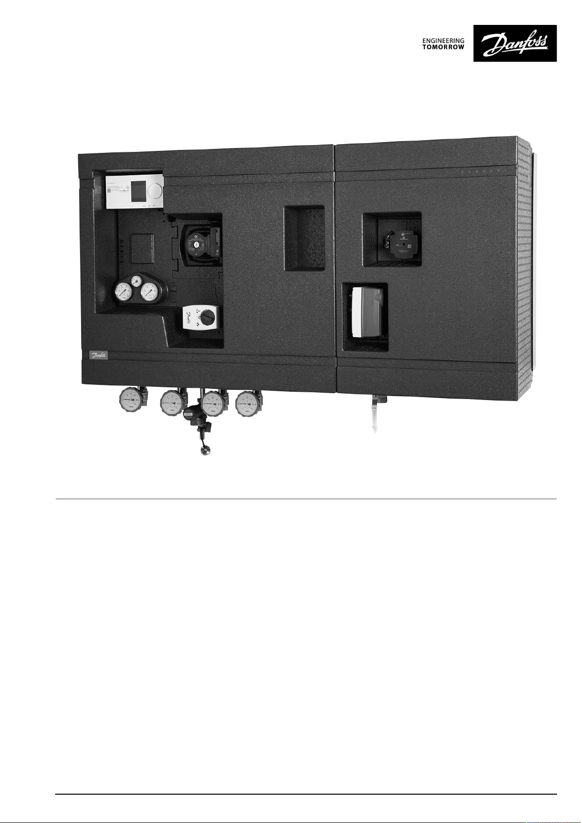
TermixCompact28VVX-FI
1.0TableofContents
1.0TableofContents.............................................1
2.0Functionaldescription......................................2
3.0Safetynotes.....................................................3
3.1SafetyNotes–general............................................3
4.0Mounting........................................................4
4.1MountingtheCompactstation..................................4
4.2Start-up..............................................................13
4.3Electricalconnections.............................................15
5.0Design.............................................................16
5.1Design...............................................................16
5.2Schematicdiagram................................................17
6.0Controls..........................................................18
6.1Heatingcircuit......................................................18
6.2DHWtemperaturecontrol........................................22
6.3Other.................................................................24
6.4Maintenance........................................................26
7.0Troubleshooting..............................................27
7.1Troubleshootingingeneral......................................27
7.2TroubleshootingDHW............................................28
7.3TroubleshootingHE...............................................29
7.4Disposal.............................................................31
8.0Declaration......................................................35
8.1Declarationofconformity........................................35
©Danfoss|2019.01VI.LZ.K2.02/LUK42463|1
Page 2

OperatingGuideTermixCompact28VVX-FI
2.0Functionaldescription
Districtheatingsubstationforindirectheatingand
instantaneousdomestichotwater.
Spaceheatinganddomestichotwater(DHW)
TheT ermixCompact28VVX-FIisacompleteunitforindirect
spaceheatinganddomestichotwaterfordistrictheatinginlarge
buildingssuchassportscentres,schools,blocksofflatsetc.
Itcanbeusedforconnectiontoindirectdistrictheatinginplaces
wherethedistrictheatingplantrequiresahydraulicbreak.Itis
alsosuitableforconversiontodistrictheatingwhenthesecondary
heatingsystemisunsuitabletobeingconnectedtodirectdistrict
heatingorwhenaparticularlyeffectivesecurityagainstleakagein
theheatingsystemisrequired.
Efficientheatexchanger
Thesubstationisfittedwithanefficientplateheatexchanger,
whichensuresthemostfavourableheatextractionandachieves
optimumcomfortandoperatingeconomy.
Electronicregulation
TheTermixCompact28VVX-FIisbuiltwithaplateheatexchanger
forinstantaneousdomestichotwaterproductionandheat
exchangerforspaceheating.Eachcircuitisalsosuppliedwithits
ownflowcontroller.
Thisallowsthegreatestdegreeofindividualcontrol,thus
preventingoscillationatdifferentloads.Theelectroniccontrolleris
factorypre-set.Electricalcomponentsarepre-wired,andtheunitis
equippedwithaplugfor230Va.c.
Itisrecommendedthatbalancingvalvesareinstalledinthe
building’srisersintheheatsupplyandontheheatingsystem’s
returnlineimmediatelybeforetheunit.
Minimalheatloss
Completeinsulationoftheunitensuresminimalheatloss.
Easyinstallation
Theunitconsistsoftwomodules,oneforspaceheatingandone
fordomestichotwaterproduction,whichiseasilyassembled
intoonesinglemodule.Thismodulardesignmakesworkduring
installationsignificantlyeasier,astheweightissplitbetweentwo
modulesduringhandling.
Flexiblesolution
Pipeconnectioncanbemadefromeitherthetoporbottom,which
makesthissolutionhighlyflexible.Atthesametime,bothspace
andtimearesavedwheninstalling.
Reliableandeasytoinstall
TermixCompact28VVX-FIisoperationallyreliable.Aquality
productmanufacturedinDenmarkwhichiseasytoinstalland
quicklycommissioned.
2|©Danfoss|2019.01
VI.LZ.K2.02/LUK42463
Page 3
OperatingGuideTermixCompact28VVX-FI
3.0Safetynotes
3.1SafetyNotes–general
Thefollowinginstructionsrefertothestandarddesignof
substation.Specialversionsofsubstationsareavailableon
request.
Thisoperatingmanualshouldbereadcarefullybeforeinstallation
andstart-upofthesubstation.Themanufactureracceptsno
liabilityfordamageorfaultsthatresultfromnon-compliancewith
theoperatingmanual.Pleasereadandfollowalltheinstructions
carefullytopreventaccidents,injuryanddamagetoproperty.
Assembly,start-upandmaintenanceworkmustbeperformedby
qualifiedandauthorizedpersonnelonly.
Pleasecomplywiththeinstructionsissuedbythesystem
manufacturerorsystemoperator.
Corrosionprotection
Allpipesandcomponentsaremadeofstainlesssteelandbrass.
Themaximumchloridecompoundsoftheflowmediumshouldnot
behigherthan150mg/l.
Theriskofequipmentcorrosionincreasesconsiderablyifthe
recommendedlevelofpermissiblechloridecompoundsis
exceeded.
Energysource
Thesubstationisdesignedfordistrictheatingastheprimary
sourceofenergy.However,alsootherenergysourcescanbeused
wheretheoperatingconditionsallowitandalwaysarecomparable
todistrictheating.
Application
Thesubstationisdesignedtobeconnectedtothehouse
installationinafrost-freeroom,wherethetemperaturedoesnot
exceed50°Candthehumiditydoesnotexceed60%.Donotcover
orwallupthesubstationorinanyotherwayblocktheentrance
tothestation.
Authorizedpersonnelonly
Assembly,start-upandmaintenanceworkmustbeperformedby
qualifiedandauthorizedpersonnelonly.
Pleaseobserveinstructionscarefully
Toavoidinjurytopersonsanddamagetothedevice,itisabsolutely
necessarytoreadandobservetheseinstructionscarefully.
Warningofhighpressureandtemperature
Beawareoftheinstallation’spermissiblesystempressureand
temperature.
Themaximumtemperatureoftheflowmediuminthesubstationis
110°C.
Themaximumoperatingpressureofthesubstationis16bar.
Theriskofpersonsbeinginjuredandequipmentdamagedincreases
considerablyiftherecommendedpermissibleoperatingparameters
areexceeded.
Thesubstationinstallationmustbeequippedwithsafetyvalves,
however,alwaysinaccordancewithlocalregulations.
Choiceofmaterial
Choiceofmaterialsalwaysincompliancewithlocallegislation.
Safetyvalve(s)
Werecommendmountingofsafetyvalve(s),however,alwaysin
compliancewithlocalregulations.
Connection
Thesubstationmustbeequippedwithfeaturesthatensurethat
thesubstationcanbeseparatedfromallenergysources(also
powersupply).
Emergency
Incaseofdangeroraccidents-fire,leaksorotherdangerous
circumstances-interruptallenergysourcestothestationif
possible,andseekexperthelp.
Incaseofdiscolouredorbad-smellingdomestichotwater,closeall
shut-offvalvesonthesubstation,informtheoperatingpersonnel
andcallforexperthelpimmediately.
REACH
AllDanfossA/SproductsfulfilltherequirementsinREACH.
OneoftheobligationsinREACHistoinformcustomersabout
presenceofCandidatelistsubstancesifany,weherebyinform
youaboutonesubstanceonthecandidatelist:Theproduct
containsbrasspartswhichcontainslead(CASno:7439-92-1)ina
concentrationabove0.1%w/w.
Storage
Anystorageofthesubstationwhichmaybenecessarypriorto
installationshouldbeinconditionswhicharedryandheated.
Warningofhotsurface
Thesubstationhasgothotsurfaces,whichcancauseskinburns.
Pleasebeextremelycautiousincloseproximitytothesubstation.
Powerfailurecanresultinthemotorvalvesbeingstuckinopen
position.Thesurfacesofthesubstationcangethot,whichcancause
skinburns.Theballvalvesondistrictheatingsupplyandreturnshould
beclosed.
Warningoftransportdamage
Beforesubstationinstallation,pleasemakesurethatthesubstation
hasnotbeendamagedduringtransport.
IMPORTANT-Tighteningofconnections
Duetovibrationsduringtransportallflangeconnections,screwjoints
andelectricalclampandscrewconnectionsmustbecheckedand
tightenedbeforewaterisaddedtothesystem.Afterwaterhasbeen
addedtothesystemandthesystemhasbeenputintooperation,
re-tightenALLconnections.
VI.LZ.K2.02/LUK42463
©Danfoss|2019.01|3
Page 4
OperatingGuideTermixCompact28VVX-FI
4.0Mounting
4.1MountingtheCompactstation
Installationmustbeincompliancewithlocalstandardsand
regulations.
Districtheating(DH)-Inthefollowingsections,DHreferstothe
heatsourcewhichsuppliesthesubstations.Avarietyofenergy
sources,suchasoil,gasorsolarpower,couldbeusedasthe
primarysupplytoDanfosssubstations.Forthesakeofsimplicity,
DHcanbetakentomeantheprimarysupply.
Connections:
1.Districtheating(DH)supply
2.Districtheating(DH)return
3.Heating(HE)supply
4.Heating(HE)return
5.Domestichotwater(DHW)
6.Domesticcoldwater(DCW)
7.Hotwatercirculation(HWC)
Authorizedpersonnelonly
Assembly,start-upandmaintenanceworkmustbeperformedby
qualifiedandauthorizedpersonnelonly.
Connectionsizes:
DH+HE:
DCW+DHW:
HWC:
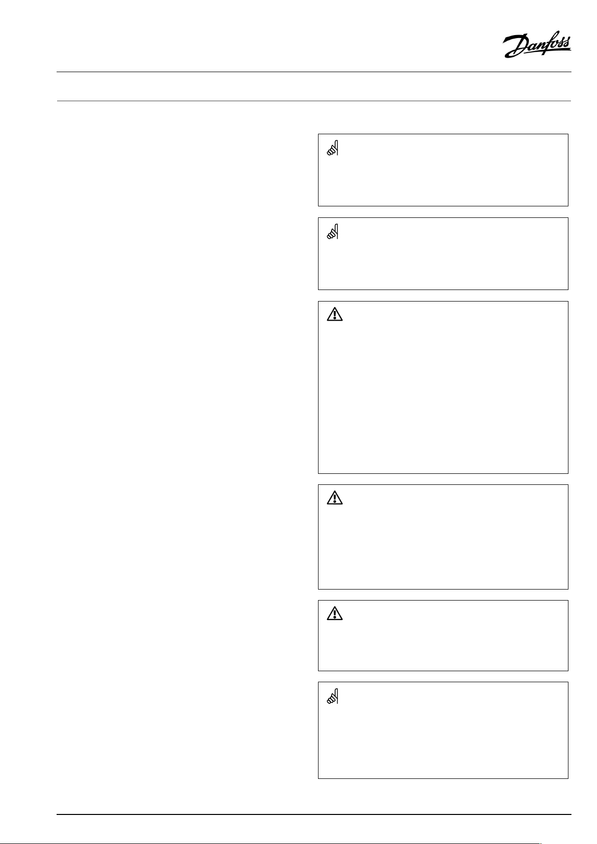
Dimensions(mm):
Withinsulation:
Weight(approx.):95kg
G1”(int.thread)
G1”(int.thread)
G¾”(int.thread)
H890xW1460xD400
Thepipeplacementcandeviatefromtheshowndrawing.Pleasenote
themarkingsonthestation.
4|©Danfoss|2019.01
VI.LZ.K2.02/LUK42463
Page 5
OperatingGuideTermixCompact28VVX-FI
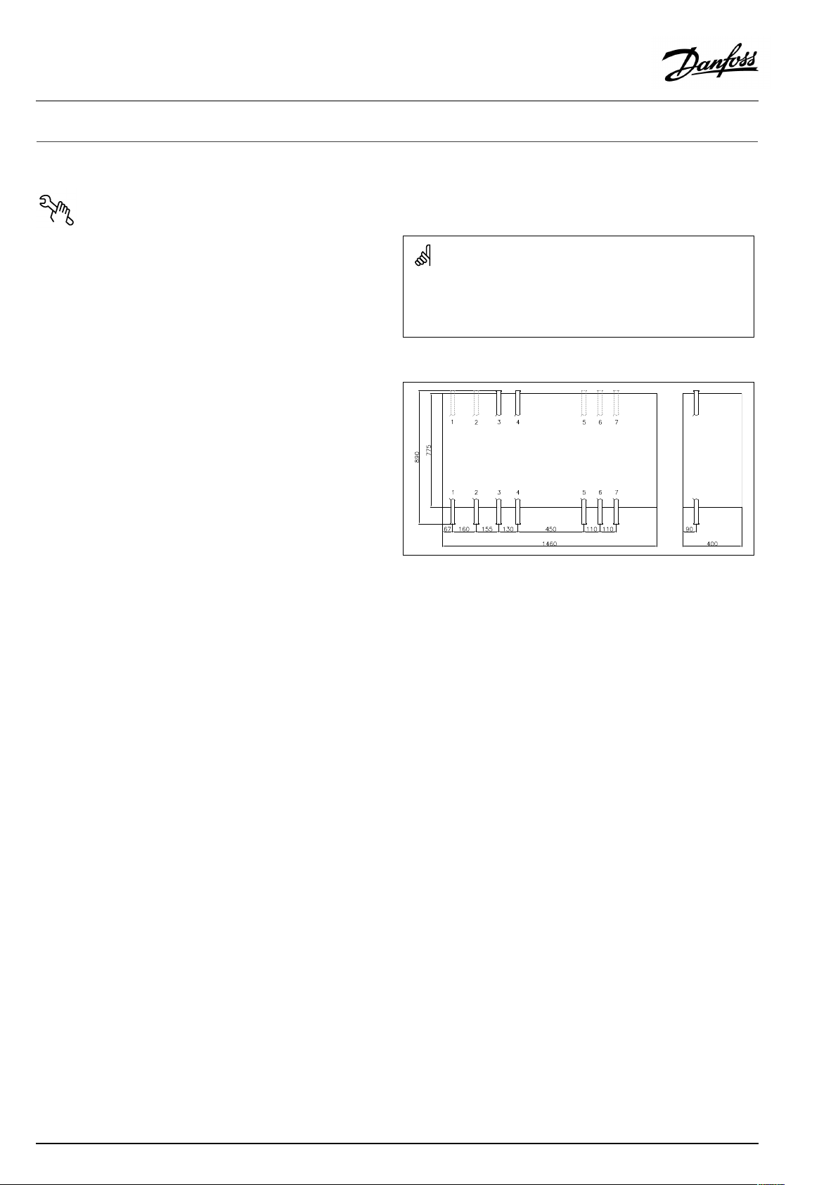
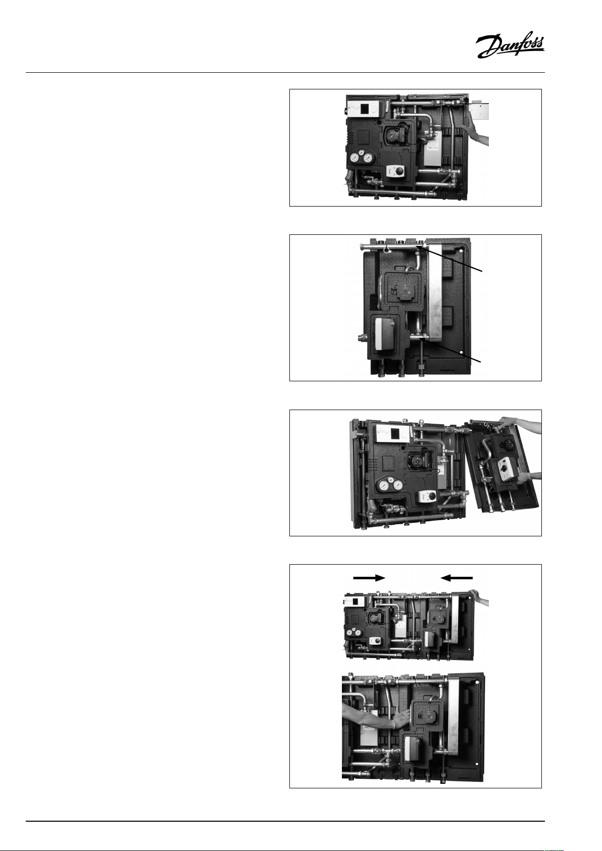
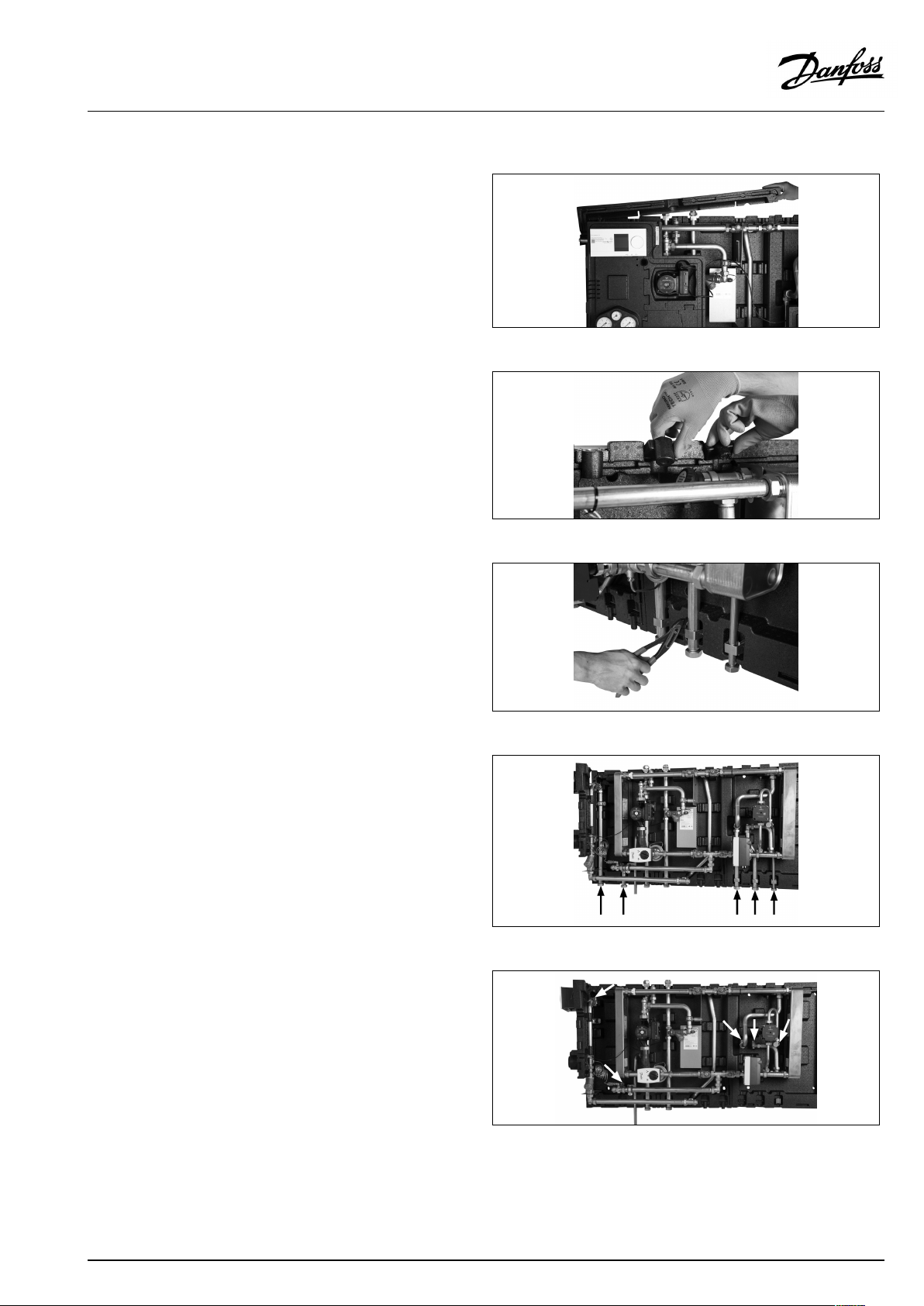
Removethefront.
Removetheotherblocksandthewhitepolystyrene.
Attachthemountingrailtothewall.
Liftthestation’sheatingsection.
VI.LZ.K2.02/LUK42463
©Danfoss|2019.01|5
Page 6
OperatingGuideTermixCompact28VVX-FI
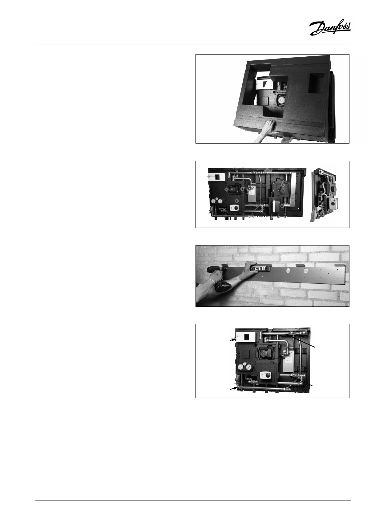
Mountthestationasfartotheleftontherailaspossible.
Liftthestation’sinstantaneousdomestichotwaterpart.
Mounttheinstantaneousdomestichotwaterpartonthe
right-handsideofthefittings.
Pushthetwopartstogether.Thetwomountingplatesmustclick
togetherintheoverlap.
6|©Danfoss|2019.01
VI.LZ.K2.02/LUK42463
Page 7
OperatingGuideTermixCompact28VVX-FI
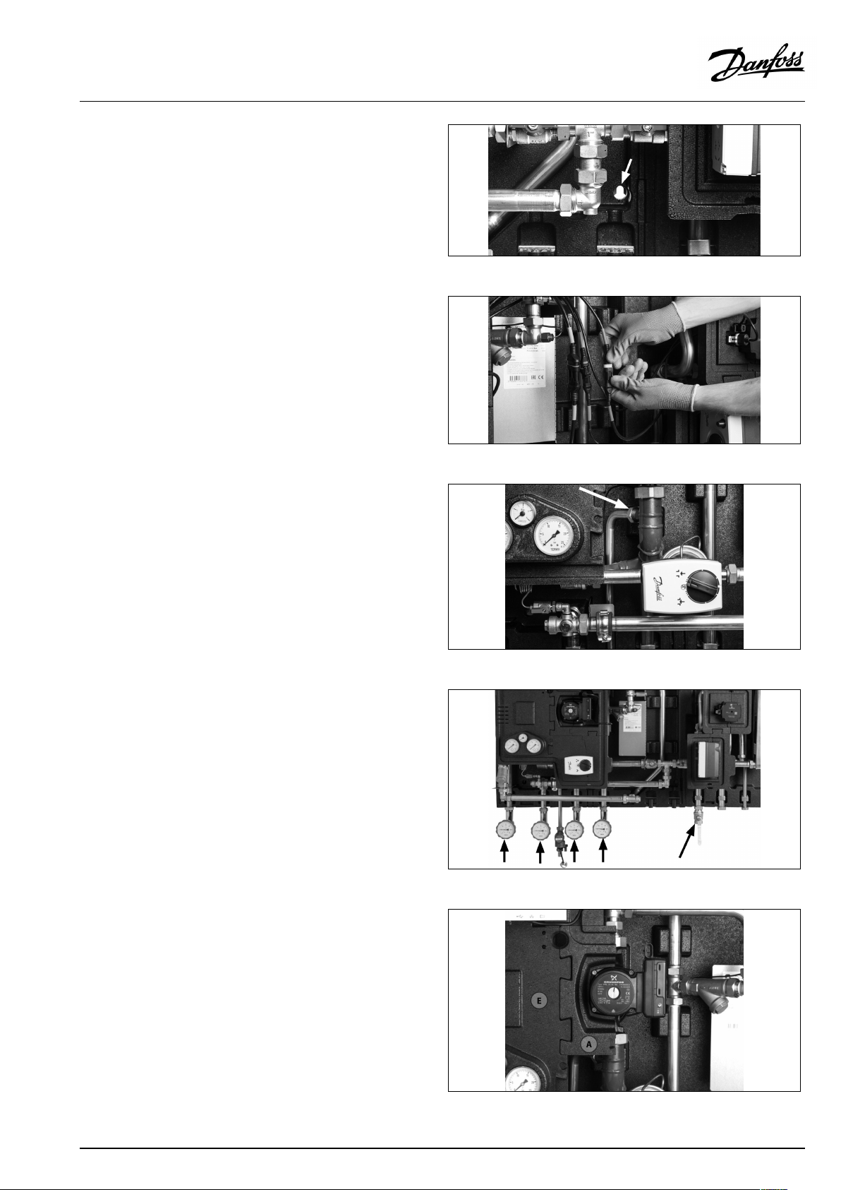
Attachthestationtothewallintheholesonthemountingplate.
Assemblethepowerconnectoronthehotwaterpartofthestation.
Forproperfunctionality,connectorsmustbepairedbycolour.
Installthesafetyvalve.
Installtheballvalves.
MountblockA(CifitistheMagnapump)ontheleft-handsideof
thepump.AttachblockEtoblockA/C,andattachittothepipe
abovethepumpbyclickingitinplace.
VI.LZ.K2.02/LUK42463
©Danfoss|2019.01|7
Page 8
OperatingGuideTermixCompact28VVX-FI
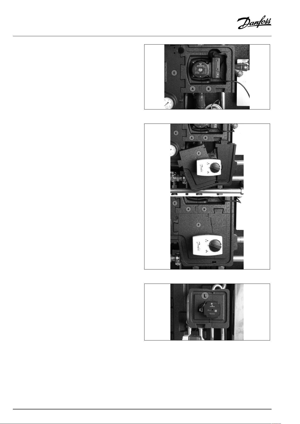
MountblockB(DifitistheMagnapump)ontheright-handsideof
thepump.
MountblockF(GforVM2valve).Theblockishingedandcanbe
drawnaroundthevalve.AttachtheblocktoblockB/DandE.
MountblockL.Theblockishingedandcanbepulledaroundthe
UPM3pump.
8|©Danfoss|2019.01
VI.LZ.K2.02/LUK42463
Page 9
OperatingGuideTermixCompact28VVX-FI
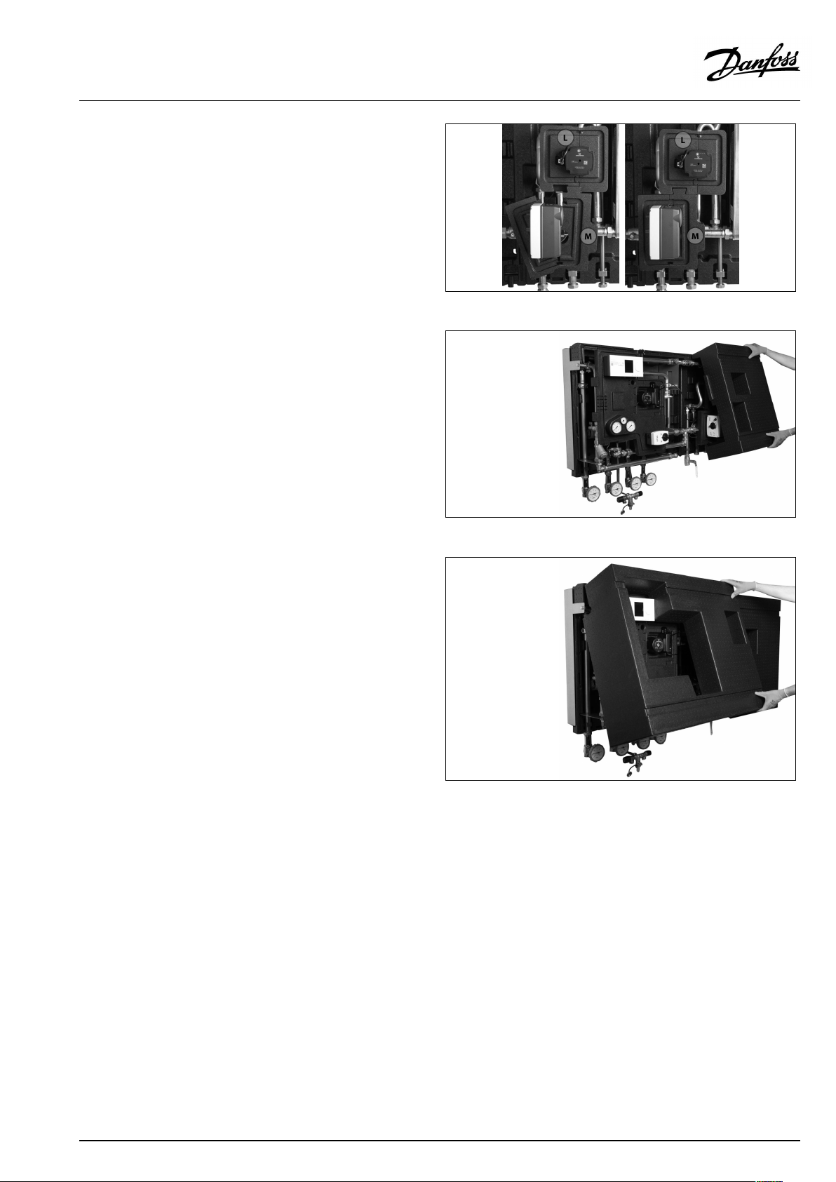
MountblockM.Theblockishingedandcanbedrawnaroundthe
valve.AttachtheblocktoblockL.
Mountthesmallfrontcover.
Mountthelargefrontcover.
VI.LZ.K2.02/LUK42463
©Danfoss|2019.01|9
Page 10
OperatingGuideTermixCompact28VVX-FI
4.1.1InstallingtheCompactstation
Mounting:
Adequatespace
Pleaseallowadequatespacearoundthesubstationformounting
andmaintenancepurposes.
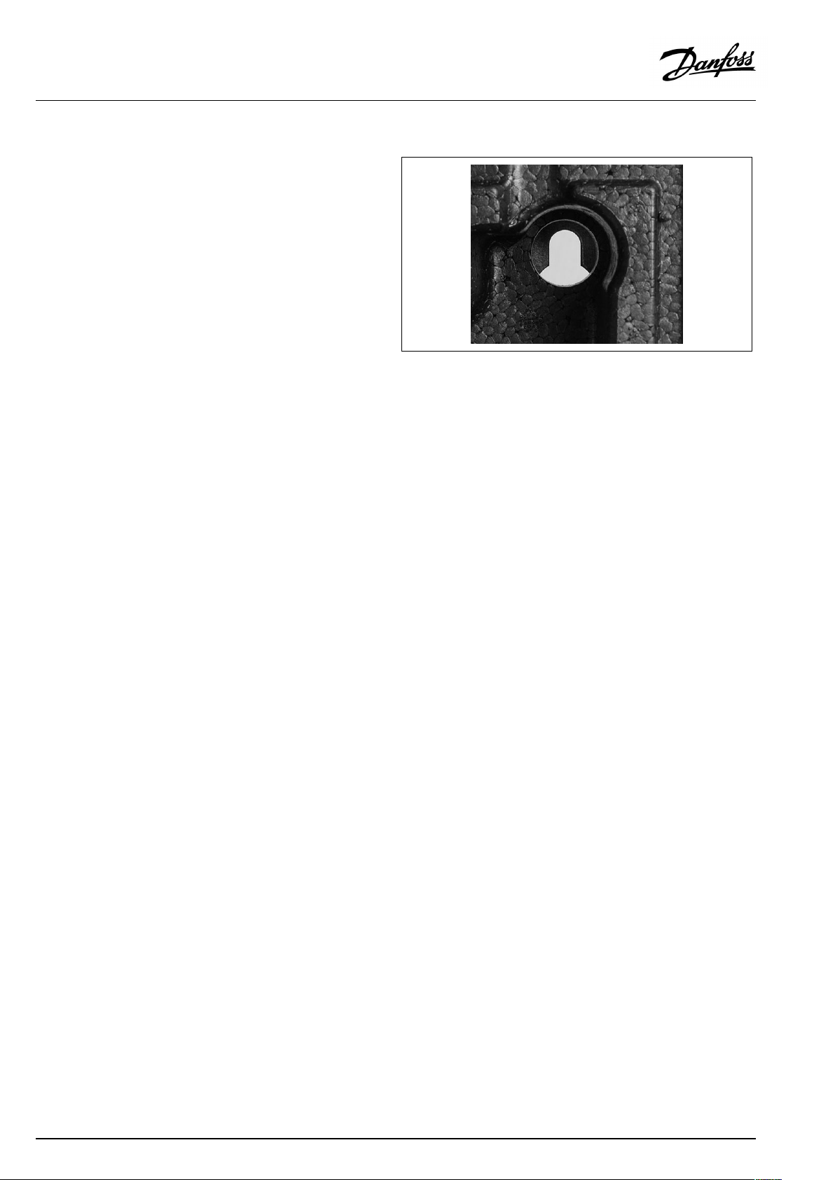
Orientation
Thestationmustbemountedsothatcomponents,keyholes
andlabelsareplacedcorrectly.Ifyouwishtomountthestation
differentlypleasecontactyoursupplier.
Drillings
Wheresubstationsaretobewall-mounted,drillingsareprovided
inthebackmountingplate.Floormountedunitshavesupport.
Labelling
Eachconnectiononthesubstationislabelled.
Beforeinstallation:
Cleanandrinse
Priortoinstallation,allsubstationpipesandconnectionsshouldbe
cleanedandrinsed.
Tightening
Duetovibrationduringtransport,allsubstationconnectionsmust
becheckedandtightenedbeforeinstallation.
Unusedconnections
Unusedconnectionsandshut-offvalvesmustbesealedwitha
plug.Shouldtheplugsrequireremoval,thismustonlybedoneby
anauthorizedservicetechnician.
Installation:
Strainer
Ifastrainerissuppliedwiththestationitmustbefittedaccording
toschematicdiagram.Pleasenotethatthestrainermaybe
suppliedloose.
Connections
Internalinstallationanddistrictheatingpipesconnectionsmustbe
madeusingthreaded,flangedorweldedconnections.
Keyholeformounting.
10|©Danfoss|2019.01
VI.LZ.K2.02/LUK42463
Page 11
OperatingGuideTermixCompact28VVX-FI
4.1.2Pipeconnectionsup
Removethetopblock.
Removethepipeplugsatthetopofthestation.
RemoveU-clamps.
Removepipes.
Anglesandteesareturnedsothatpipescanbeinstalledfrom
above.
VI.LZ.K2.02/LUK42463
©Danfoss|2019.01|11
Page 12

OperatingGuideTermixCompact28VVX-FI
Installthepipes.Districtheatingsupplypipestobeinterchanged.
FitU-clamps.
Fitthepipeplugsatthebottomofthestation.
Fitthetopblock.
12|©Danfoss|2019.01
VI.LZ.K2.02/LUK42463
Page 13

OperatingGuideTermixCompact28VVX-FI
4.2Start-up
Start-up,Indirectheating
Filling:
1:Firstfill
Whencarryingoutfirstfill,theheatexchangermustbeslowlyfilled
withwateruntilitreachesworkingpressure.
2:Pressuregauge
TheHEpressuregaugeindicatesthepressureoftheHEsystem.This
instructionmustbefollowedstrictly,toavoiddangeroussituations.
3:Supplyhose
AballvalvewithplugisinstalledintheHEreturnline.Tofillthe
system,theballvalvemustfirstbeclosed,theplugremovedand
asupplyhoseconnected.Onre-openingtheballvalve,system
fillcancommence.
4:Pre-pressure
Whenfillingthesystemwithwater,thepressuregaugeshouldbe
observedclosely.Theexpansionvesselissuppliedpre-pressurised
to0.5bar.Thepre-pressurerequiredateachsubstationwill
dependonsystemhead(thedistancebetweenthelowestand
highestpointinthesystem),forexample:
5:Fillingstop
Fillingmuststopwhenthepressuregaugeshowsapressure
approximately1-2barhigherthanthepre-pressuresetting.The
ballvalveisthenclosed,thehoseremovedandtheplugputback
in.
Re-tightenconnections
Afterwaterhasbeenaddedtothesystemandthesystemhasbeen
putintooperation,re-tightenALLconnections.
Pump
Thepumpmustbeswitchedoffduringsystemfill.
Height(m)Pressure(bar)
0–50,5
5–101,0
10–15
1,5
15–202,0
Start-up:
1:Pumpspeed
Setthepumptohighestspeedbeforestart-up.
2:Startpump
Startthepumpandheatthroughthesystem.
3:Openshut-offvalves
Theshut-offvalvesshouldthenbeopenedandtheunitobserved
asitentersservice.Visualcheckingshouldconfirmtemperatures,
pressures,acceptablethermalexpansionandabsenceofleakage.
Iftheheatexchangeroperatesinaccordancewithdesign,itcanbe
puttoregularuse.
4:Ventsystem
Switchoffthepumpandventtheinstallationaftertheradiators
havebeenwarmedup.
5:Adjustpumpspeed
Setthepumptothelowestspeedconsistentwithcomfortand
electricityconsumption.
Normallythechange-overswitchissetinthemidposition(default).
Howeverforsystemswithunderfloorheatingorsinglepipeloop
systems,itmaybenecessarytoturnthechange-overswitch
upwards.
Higherpumpspeedsareonlyusediftheheatingrequirement
increases.
VI.LZ.K2.02/LUK42463
©Danfoss|2019.01|13
Page 14

OperatingGuideTermixCompact28VVX-FI
Underfloorheating:
Pumpstopfunction
Ifthesubstationisusedinconnectionwithunderfloorheating,the
circulationpumpmustbeconnectedtothepumpstopfunctionin
theunderfloorheatingcontroller.Thepumpmustbestoppedif
allunderfloorheatingcircuitsareclosed.
Warranty
Ifthisisnotpossible,thenflowmustbecontinuedthroughthe
by-pass.Failingthis,thepumpwillbeatriskofseizureandany
remainingwarrantywillbewithdrawn.
Summeroperation:
Switchoffpump
Insummerthecirculationpumpmustbeswitchedoffandthe
shut-offvalvetoHEsupplyclosed.
Runningpumpbi-weekly
Itisrecommendedtostartupthecirculationpump(for2minutes)
onceamonthduringsummer;theshut-offvalveoftheHEsupply
mustbeshut.
Electroniccontroller
Mostelectroniccontrollerswillstartupthepumpautomatically
(pleasenotemanufacturer´sinstructions).
14|©Danfoss|2019.01
VI.LZ.K2.02/LUK42463
Page 15

OperatingGuideTermixCompact28VVX-FI
4.3Electricalconnections
Beforemakingelectricalconnections,pleasenotethe
following:
Safetynotes
Pleasereadtherelevantpartsofthesafetynotes.
230V
Thesubstationmustbeconnectedto230VACandearth.
Potentialbonding
Potentialbondingshouldbecarriedoutaccording
to60364-4-41:2007andIEC60364-5-54:2011.
Bondingpointonthemountingplatebelowrightcornermarked
withearthsymbol.
Disconnection
Thesubstationmustbeelectricallyconnectedsothatitcanbe
disconnectedforrepairs.
Outdoortemperaturesensor
Outdoorsensorsshouldbemountedsoastoavoidexposureto
directsunlight.Theyshouldnotbeplacedclosetodoors,windows
orventilationoutlets.
Theoutdoorsensormustbeconnectedtothestationonthe
terminalblockundertheelectroniccontrol.
Authorizedelectrician
Electricalconnectionsmustbemadebyanauthorizedelectricianonly.
Localstandards
Electricalconnectionsmustbemadeinaccordancewithcurrent
regulationsandlocalstandards.
VI.LZ.K2.02/LUK42463
©Danfoss|2019.01|15
Page 16

OperatingGuideTermixCompact28VVX-FI
5.0Design
5.1Design
Yoursubstationmightlookdifferentthanthesubstationshown.
Designdescription
A
Heatexchanger,HE
B
Heatexchanger,DHW
F
Electroniccontroller
4
Safetyvalve,HE
9
Strainer
16|©Danfoss|2019.01
10
Circulatorpump
11
Domestichotwaterpump
14
Sensorpocket,energymeter
20
Filling/drainvalve
25
Pressuregaugewithballvalve
26
Pressuregauge,HE
27AActuator,HE
27BActuator,DHW
48
Airvent,manual
VI.LZ.K2.02/LUK42463
Page 17

OperatingGuideTermixCompact28VVX-FI
5.2Schematicdiagram
DH
Supply
DH
Return
Yoursubstationmightlookdifferentthantheschematicdiagramshown.
Schematicdescription
A
Heatexchanger,HE
B
Heatexchanger,DHW
F
Electroniccontroller
X
Plugconnections
1
Ballvalve
2
Singlecheckvalve
4
Safetyvalve
9
Strainer
10
Circulatorpump
11
Domestichotwaterpump
14
Sensorpocket,energymeter
16
Outdoorsensor
18
Thermometer
19
Surfacesensor
20
Filling/drainvalve
24
Deliveredloosewithunit
25
Pressuregaugewithballvalve
26
Pressuregauge
27
Actuator
30
Flowcontrollerwithintegratedcontrolvalve
40
Immersionsensor
48
Airvent,manual
HE
Supply
HE
Return
DHW
DCW
HWC
DHSupply:DistrictHeatingSupply
DHReturn:DistrictHeatingReturn
HESupply:HeatingSupply
HEReturn:HeatingReturn
DHW:
HWC:
DCW:
5.2.1Technicalparameters
Nominalpressure:
Max.DHsupplytemperature:
Min.DCWstaticpressure:
Brazingmaterial(HEX):
Heatexchangerstestpressure:30bar
Soundlevel:≤55dB
Domestichotwater
Hotwatercirculation
Domesticcoldwater
PN16
110°C
0.5bar
Copper
VI.LZ.K2.02/LUK42463
©Danfoss|2019.01|17
Page 18

OperatingGuideTermixCompact28VVX-FI
6.0Controls
6.1Heatingcircuit
6.1.1Differentialpressurecontroller
Thedifferentialpressurecontrollersmoothsoutthefluctuationsin
pressurearrivingfromthedistrictheatingnetwork.Theoperating
pressureinthesubstationisthusheldsteady.
6.1.2HEtemperaturecontrol
TheHEflowtemperatureintheheatingcircuitiscontrolledbythe
HEtemperaturecontroller.
6.1.3Flowcontrollerwithintegratedcontrolvalve
Thecontrollerisaself-actingflowcontrollerwithintegratedcontrol
valve.Thecontrollercloseswhensetmax.flowisexceededand
canbeusedincombinationwithDanfosselectricalactuatorswith
orwithoutsafetyfunction.Springreturnmotorcanbeusedas
safetyfunctionbypowerfailure.
18|©Danfoss|2019.01
VI.LZ.K2.02/LUK42463
Page 19

OperatingGuideTermixCompact28VVX-FI
6.1.4Electric2–waymotorizedvalve
Actuatorswithorwithoutsafetyfunctionareavailablefor3-point
controls.Spring-returnactuatorscanbeusedtoprovidesafety
shut-offintheeventofpowerfailure.
6.1.5Electroniccontrol
Substationswithelectroniccontrolmustbesetinaccordancewith
manufacturer´sinstructions.
Wheretheroomtemperatureiscontrolledbyradiatorthermostats,
itisrecommendedthatthermostatsbesetforminimum
temperatureineachroom.
6.1.6Outsidetemperaturesensor
Outdoorsensorsshouldbemountedsoastoavoidexposureto
directsunlight.Theyshouldnotbeplacedclosetodoors,windows
orventilationoutlets.
VI.LZ.K2.02/LUK42463
©Danfoss|2019.01|19
Page 20

OperatingGuideTermixCompact28VVX-FI
6.1.7Circulatorpump
TheUPML,UPMXLcirculatorpumpsaredesignedforcirculating
liquidsinheatingsystemswithvariableflows,internallycontrolled
withthreeproportionalpressurecurvesandthreeconstant
pressure/powercurvestobeselectedviauserinterface.
EuP2015Ready.
TheMAGNA3circulatorpumpsaredesignedforcirculatingliquids
inheatingsystemswithvariableflowswhereyouwanttooptimise
thesettingofthepumpdutypoint,thusreducingenergycosts.
EuP2015Ready.
6.1.8GrundfosUPML/UPMXLinstructions
PP=Proportionalpressure(fastflash)
CP=Constantpressure(slowflash)
20|©Danfoss|2019.01
VI.LZ.K2.02/LUK42463
Page 21

OperatingGuideTermixCompact28VVX-FI
6.1.9HEpressuregauge
TheHEpressuregaugeindicatesthepressureoftheHEsystem.
VI.LZ.K2.02/LUK42463
©Danfoss|2019.01|21
Page 22

OperatingGuideTermixCompact28VVX-FI
6.2DHWtemperaturecontrol
DHWtemperaturecontrol
TherearevarioustypesofDHWtemperaturecontrolusedin
Danfosssubstations.
DHWtemperatureshouldbeadjustedto45-50°C,asthisprovides
optimalutilisationofDHwater.AtDHWtemperaturesabove55°C,
thepossibilityoflimescaledepositsincreasessignificantly.
6.2.1Flowcontrollerwithintegratedcontrolvalve
Thecontrollerisaself-actingflowcontrollerwithintegratedcontrol
valve.Thecontrollercloseswhensetmax.flowisexceededand
canbeusedincombinationwithDanfosselectricalactuatorswith
orwithoutsafetyfunction.Springreturnmotorcanbeusedas
safetyfunctionbypowerfailure.
6.2.2Electric2–waymotorizedvalve
Actuatorswithorwithoutsafetyfunctionareavailablefor3-point
controls.Spring-returnactuatorscanbeusedtoprovidesafety
shut-offintheeventofpowerfailure.
22|©Danfoss|2019.01
VI.LZ.K2.02/LUK42463
Page 23

OperatingGuideTermixCompact28VVX-FI
6.2.3Domestichotwaterpump
Important!
Itisnecessarytomountadomestichotwatercirculationpumpon
thewaterheatertoavoidregulationproblems.
Thecirculationpumpcannotbeswitchedoff,sincethiswillresult
inregulationproblems.(noflowatthesensor).
VI.LZ.K2.02/LUK42463
©Danfoss|2019.01|23
Page 24

OperatingGuideTermixCompact28VVX-FI
6.3Other
6.3.1Safetyvalve
Thepurposeofthesafetyvalveistoprotectthesubstationfrom
excessivepressure.
Theblow-offpipefromthesafetyvalvemustnotbeclosed.The
blow-offpipeoutletshouldbeplacedsothatitdischargesfreely
anditispossibletoobserveanydrippingfromthesafetyvalve.
Itisrecommendedtochecktheoperationofsafetyvalvesat
intervalsof6months.Thisisdonebyturningthevalveheadin
directionindicated.
6.3.2Strainer
Strainersshouldbecleanedregularlybyauthorizedpersonnel.The
frequencyofcleaningwoulddependonoperatingconditionsand
themanufacturer’sinstructions.
24|©Danfoss|2019.01
VI.LZ.K2.02/LUK42463
Page 25

OperatingGuideTermixCompact28VVX-FI
6.3.3Fittingpiece
Thesubstationisequippedwithafittingpieceforenergymeter.
Assemblyofenergymeters:
1:Closeballvalves
ClosetheballvalvesonDHSupplyandDHReturn,ifthereiswater
onthesystem.
2:Loosennuts
Loosenthenutsonthefittingpiece.
3:Removefittingpiece
Removethefittingpieceandreplaceitwiththeenergymeter.Do
notforgetthegaskets.
4:Tightenconnections
Aftermountingoftheenergymeterremembertocheckand
tightenallthreadedconnections.
Sensorpocket,energymeter
Thesensorsoftheenergymeterismountedinthesensorpockets.
VI.LZ.K2.02/LUK42463
©Danfoss|2019.01|25
Page 26

OperatingGuideTermixCompact28VVX-FI
6.4Maintenance
Thesubstationrequireslittlemonitoring,apartfromroutine
checks.Itisrecommendedtoreadtheenergymeteratregular
intervals,andtowritedownthemeterreadings.
RegularinspectionsofthesubstationaccordingtothisInstruction
arerecommended,whichshouldinclude:
Strainers
Cleaningofstrainers.
Meters
Checkingofalloperatingparameterssuchasmeterreadings.
Temperatures
Checkingofalltemperatures,suchasDHsupplytemperatureand
DHWtemperature.
Connections
Checkingallconnectionsforleakages.
Safetyvalves
Theoperationofthesafetyvalvesshouldbecheckedbyturning
thevalveheadintheindicateddirection.
Venting
Checkingthatthesystemisthoroughlyvented.
Authorizedpersonnelonly
Assembly,start-upandmaintenanceworkmustbeperformedby
qualifiedandauthorizedpersonnelonly.
Inspectionsshouldbecarriedoutminimumeverytwoyears.
SparepartscanbeorderedfromDanfoss.Pleaseensurethatany
enquiryincludesthesubstationserialnumber.
26|©Danfoss|2019.01
VI.LZ.K2.02/LUK42463
Page 27

OperatingGuideTermixCompact28VVX-FI
7.0Troubleshooting
7.1Troubleshootingingeneral
Intheeventofoperatingdisturbances,thefollowingbasicfeatures
shouldbecheckedbeforecarryingoutactualtroubleshooting:
•thesubstationisconnectedtoelectricity,
•thestrainerontheDHsupplypipeisclean,
•thesupplytemperatureoftheDHisatthenormallevel
(summer,atleast60°C-winter,atleast70°C),
•thedifferentialpressureisequaltoorhigherthanthenormal
(local)differentialpressureintheDHnetwork–ifindoubt,ask
theDHplantsupervisor,
•pressureonthesystem-checktheHEpressuregauge.
Authorizedpersonnelonly
Assembly,start-upandmaintenanceworkmustbeperformedby
qualifiedandauthorizedpersonnelonly.
VI.LZ.K2.02/LUK42463
©Danfoss|2019.01|27
Page 28
OperatingGuideTermixCompact28VVX-FI
7.2TroubleshootingDHW
ProblemPossiblecauseSolution
ToolittleornoDHW.
Taptemperaturetoohigh;DHWtapload
toohigh.
Temperaturedropduringtapping.
Thermostaticcontrolvalvedoesnotclose
Strainerinsupplyorreturnlineclogged.Cleanstrainer(s).
DHWcirculationpumpoutoforderorwith
toolowsetting.
Defectiveorcloggednon-returnvalve.
Noelectricity.Check.
Wrongsettingofautomaticcontrols,ifany.Toadjustanelectroniccontrollerfor
Scalingoftheplateheatexchanger.
Defectivemotorizedvalve.Check(usemanualfunction)–replace.
Defectivetemperaturesensors.
Defectivecontroller.
DCWisbeingmixedwiththeDHW,e.g.ina
defectivethermostaticmixingvalve.
Defectiveorcloggednon-returnvalveon
circulationvalve.
Thermostaticvalveadjustedtoatoohigh
level.
Scalingoftheplateheatexchanger.
LargerDHWflowthanthesubstationhas
beendesignedfor.
TemperaturedifferencebetweenDH
supplyandDHWsetpointtoolow.
Checkcirculationpump.
Replace–clean.
DHW,pls.noteenclosedinstructionsfor
electroniccontroller.
Replace–rinseout.
Check–replace.
Check–replace.
Check–replace. Hotwaterinsometapsbutnotinall.
Replace–clean.
Check–set.
Replace–rinseout.
ReduceDHWflow.
Lowerthesetpointtemperatureorincrease
theDHsupplytemperature.
28|©Danfoss|2019.01
VI.LZ.K2.02/LUK42463
Page 29
OperatingGuideTermixCompact28VVX-FI
7.3TroubleshootingHE
ProblemPossiblecauseSolution
Toolittleornoheat.StrainercloggedinDHorHEcircuit
Unevenheatdistribution.Airpocketsinthesystem.Venttheinstallationthoroughly.
DHsupplytemperaturetoohigh.
DHsupplytemperaturetoolow.
(radiatorcircuit).
ThefilterintheenergymeteronDHcircuit
clogged.
Defectiveorwronglyadjusteddifferential
pressurecontroller.
Sensordefective–orpossiblydirtinthe
valvehousing.
Automaticcontrols,ifany,wronglysetor
defective-possiblypowerfailure.
Pumpoutofoperation.Checkifthepumpisreceivingpowerand
Thepumpissetattoolowspeedof
rotation.
Pressuredrop–thepressuredropon
theradiatorcircuitshowslowerthan
recommendedoperatingpressure.
Airpocketsinthesystem.Venttheinstallationthoroughly.
Limitingofthereturntemperatureadjusted
toolow.
Defectiveradiatorvalves.
Unevenheatdistributioninbuilding
becauseofincorrectlysetbalancingvalves,
orbecausetherearenobalancingvalves.
Diameterofpipetosubstationtoosmallor
branchpipetoolong.
Wrongsettingofthermostatorof
automaticcontrols,ifany.
Defectivecontroller.Thecontrollerdoes
notreactasitshouldaccordingtothe
instructions.
Defectivesensoronself-actingthermostat.
Wrongsettingofautomaticcontrols,ifany.
Defectivecontroller.Thecontrollerdoes
notreactasitshouldaccordingtothe
instructions.
Defectivesensoronself-actingthermostat.
Wrongplacement/fittingofoutdoor
temperaturesensor.
Strainerclogged.Cleangate/strainer.
Cleangate/strainer(s).
Cleanthefilter(afterconsultingtheDH
plantoperator).
Checktheoperationofthedifferential
pressurecontroller–cleanthevalveseatif
required.
Checktheoperationofthethermostat–
cleanthevalveseatifrequired.
Checkifthesettingofthecontroller
iscorrect–seeseparateinstructions.
Checkthepowersupply.Temporary
settingofmotorto“manual”control–see
instructionsonautomaticcontrols.
thatitturns.Checkifthereisairtrappedin
thepumphousing–seepumpmanual.
Setthepumpathigherspeedofrotation.
Fillwateronthesystemandcheckthe
functioningofthepressureexpansion
vesselifrequired.
Adjustaccordingtoinstructions.
Check–replace.
Adjust/installbalancingvalves.
Checkpipedimensions.
Adjustautomaticcontrols,–see
instructionsforautomaticcontrols.
Callautomaticcontrolsmanufactureror
replacetheregulator.
Replacethermostat–orsensoronly.
Adjustautomaticcontrols–seeinstructions
forautomaticcontrols.
Callinautomaticcontrolsmanufactureror
replacecontroller.
Replacethermostat–orsensoronly.
Adjustlocationofoutdoortemperature
sensor.
VI.LZ.K2.02/LUK42463
©Danfoss|2019.01|29
Page 30

OperatingGuideTermixCompact28VVX-FI
ToohighDHreturntemperature.
Noiseinsystem.
Heatloadtoohigh.
Toosmallheatingsurface/toosmall
radiatorscomparedtothetotalheating
requirementofthebuilding.
Poorutilizationofexistingheatingsurface.
Defectivesensoronself-actingthermostat.
Thesystemissinglepipeloop.
Pumppressuretoohigh.Adjustpumptoalowerlevel.
Airinsystem.
Defectiveorincorrectlysetradiatorvalve(s).
Singlepipeloopsystemsrequirespecial
one-piperadiatorvalves.
Dirtinthemotorizedvalveorinthe
differentialpressurecontroller.
Defectivemotorizedvalve,sensoror
automaticcontroller.
Electroniccontrollernotadjustedcorrectly.Adjustaccordingtoinstructions.
Pumppressuretoohigh.Adjustpumptoalowerlevel.
Defectivemotorizedvalve,sensoror
electroniccontroller.
Increasetotalheatingsurface.
Makesuretheheatisdistributedevenly
acrossthefullheatingsurface–openall
radiatorsandkeeptheradiatorsinthe
systemfromheatingupatthebottom.It
isextremelyimportanttokeepthesupply
temperaturetotheradiatorsaslowas
possible,whilemaintainingareasonable
levelofcomfort.
Thesystemshouldfeatureelectronic
controlsaswellasreturnsensors.
Ventthesystem.
Check–set/replace.
Check–cleanout.
Check–replace.
Check–replace.
30|©Danfoss|2019.01
VI.LZ.K2.02/LUK42463
Page 31

OperatingGuideTermixCompact28VVX-FI
7.4Disposal
Disposal
Thisproductshouldbedismantledanditscomponents
sorted,ifpossible,invariousgroupsbeforerecycling
ordisposal.
Alwaysfollowthelocaldisposalregulations.
VI.LZ.K2.02/LUK42463
©Danfoss|2019.01|31
Page 32

OperatingGuideTermixCompact28VVX-FI
32|©Danfoss|2019.01
VI.LZ.K2.02/LUK42463
Page 33

OperatingGuideTermixCompact28VVX-FI
33|©Danfoss|2019.01
VI.LZ.K2.02/LUK42463
Page 34

OperatingGuideTermixCompact28VVX-FI
34|©Danfoss|2019.01
VI.LZ.K2.02/LUK42463
Page 35

OperatingGuideTermixCompact28VVX-FI
8.0Declaration
8.1Declarationofconformity
Category0withelectricalequipment
VI.LZ.K2.02/LUK42463
©Danfoss|2019.01|35
Page 36

OperatingGuideTermixCompact28VVX-FI
36|©Danfoss|2019.01
VI.LZ.K2.02/LUK42463
 Loading...