

Page 1
Installation Instruction
Cable to cable Splice
Heat shrink technology connection system
Page 2
Installation Instruction
Cable to cable Splice - Heat shrink technology connection system
Table of contents
1 Overview � � � � � � � � � � � � � � � � � � � � � � � � � � � � � � � � � � � � � � � � � � 2
2 Certications / Approvals� � � � � � � � � � � � � � � � � � � � � � � � � � � � � � � � � � � � 3
3 Technical data � � � � � � � � � � � � � � � � � � � � � � � � � � � � � � � � � � � � � � � � � � � 3
4 Safety � � � � � � � � � � � � � � � � � � � � � � � � � � � � � � � � � � � � � � � � � � � � � � � � 4
5 Kit contents � � � � � � � � � � � � � � � � � � � � � � � � � � � � � � � � � � � � � � � � � � � � 5
6 Installation � � � � � � � � � � � � � � � � � � � � � � � � � � � � � � � � � � � � � � � � � � � � � 6
Required tools / equipment . . . . . . . . . . . . . . . . . . . . . . . . . . . . . . . . . . . . . 6
Cautions and warnings . . . . . . . . . . . . . . . . . . . . . . . . . . . . . . . . . . . . . . . .6
Preparation of trace heaters . . . . . . . . . . . . . . . . . . . . . . . . . . . . . . . . . . . . . 7
Trace heater to trace heater connection . . . . . . . . . . . . . . . . . . . . . . . . . . . . . 11
7 Troubleshooting � � � � � � � � � � � � � � � � � � � � � � � � � � � � � � � � � � � � � � � � 11
Cold lead cable to trace heater connection . . . . . . . . . . . . . . . . . . . . . . . . . . . 17
Installation of the end seal . . . . . . . . . . . . . . . . . . . . . . . . . . . . . . . . . . . . . 22
8 Troubleshooting � � � � � � � � � � � � � � � � � � � � � � � � � � � � � � � � � � � � � � � � 25
9 Safety � � � � � � � � � � � � � � � � � � � � � � � � � � � � � � � � � � � � � � � � � � � � � � � 26
10 Sécurité et advertissements � � � � � � � � � � � � � � � � � � � � � � � � � � � � � � � � � 27
1 Overview
This manual introduces the installation and operation of Danfoss heat shrink splice technology. The
connection is established using splice lugs and sealed with heat shrink tubes. Catalog No.: 088L0006.
The trace heating system uses a self-regulating trace heater. It features a temperature-dependent
resistive heating element that regulates and limits the heat according to the ambient temperature. If
the ambient temperature rises, the power output of the trace heater is reduced. This self-regulating
property prevents overheating which would cause damage to the trace heater. Even crossing or overlapping with other trace heaters (or other portions of the same trace heater) are possible.
The heating system is set up as a xed equipment heating system for pipes in ordinary areas. Thanks to
the parallel design the trace heater can be cut and installed to any required length (mind the maximum
heating circuit length according to system’s design guide).
It is suitable for the following self-regulating trace heaters:
• Danfoss PX Pipe Trace Heating System
• Danfoss RX-C Roof and Gutter De-Icing System
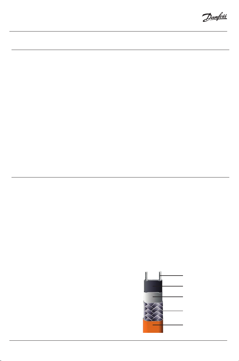
bus wire
heating matrix
insulation jacket
The following terms describe the parts of the trace heater
within these instructions:
grounding braid
outer jacket
2 | © Danfoss | 2022.02
AN396730292442en-US0103
Page 3

Installation Instruction
Cable to cable Splice - Heat shrink technology connection system
2 Certications / Approvals
Heat shrink technology connection system for Danfoss PX/RX trace heaters.
3 Technical data
Ambient temperature range -67 to +185 °F / -55 to +85° C
Operation temperature range -67 to +185 °F / -55 to +85° C
Min. installation temperature -4 °F / -20 °C
Max. circuit load 24 A
Ingress protection NEMA Type 4X
Protection classication N/A - for use in ordinary locations only!
AN396730292442en-US0103
© Danfoss | 2022.02 | 3
Page 4

Installation Instruction
4 Safety
Cable to cable Splice - Heat shrink technology connection system
Safety
For safe installation and operation of the cold applied
connection system the technical requirements and
instructions given in this manual must be followed.
WARNING
Risk of re or electrical shock. Follow these guidelines to
avoid personal injury or material damage.
• All electrical systems and installations must comply
with Danfoss requirements and be installed in
accordance with the relevant electrical codes and any
other applicable national and local codes.
• The US and Canadian electrical codes require ground
fault protection to be provided for all trace heating
circuits.
• Install the connection system and trace heaters
carefully.
• Use the trace heater and connection system in
accordance with the intended purpose and strictly
comply with the operational data specied in section
Technical Data.
• The bending radius of the trace heater must be at least
1” (25 mm).Do not bend on the narrow axis.
• Any defective component of the kit must be replaced
before installation.
• To avoid short circuits, do not connect the trace heater
bus wires together.
• Keep all components and the trace heaters dry before
and during installation.
• Beware of hot surfaces when using the heat gun.
• Keep these instructions for future reference.If
applicable, leave them with the end user.
• De-energize before installation or servicing.
• Use only original accessories.
NOTICE
The following instructions are provided in English only.
Refer to www.danfoss.com for the French version.
Sécurité
An de garantir la sécurité lors de l’installation et de
l’utilisation du système de connexion à liaison froide, il est
impératif de respecter les exigences ainsi que les consignes
techniques mentionnées dans le présent manuel.
AVERTISSEMENT
Risque d’incendie ou d’électrocution. Suivez ces consignes
pour éviter toute blessure ou dommage matériel.
• Tous les systèmes et installations électriques doivent
satisfaire aux exigences imposées par la société
Danfoss et doivent être installés conformément aux
normes électriques en vigueur ainsi qu’aux autres
prescriptions nationales et locales applicables.
• Les normes électriques américaines et canadiennes
imposent une protection contre les défauts à la terre
pour tous les circuits de traçage électrique.
• Notez que le guide de conception fourni avec chaque
cable chauant contient des informations importantes
additionalles qu’il convient de respecter en plus du
present manuel.
• La pose du système de connexion et des câbles
chauants doit être réalisée avec le plus grand soin.
• Utilisez le câble chauant et le système de
connexion adaptés à l’usage prévu et répondant aux
caractéristiques de fonctionnement spéciées à la
section Caractéristiques techniques.
• Le rayon de courbure du câble chauant ne doit pas
être inférieur à 1” (25 mm).Ne pas courber le câble
chauant sur la tranche.
• Tout élément défectueux dans le kit doit être remplacé
avant l’installation.
• Pour éviter un court-circuit, ne jamais raccorder
ensemble les deux conducteurs du câble chauant.
• Conservez tous les éléments et les câbles chauants
au sec avant et pendant l’installation.
• Soyez prudent lors de l’utilisation du pistolet à air
chaud, certaines surfaces peuvent devenir brûlantes.
• Conservez ces instructions pour un usage ultérieur.Le
cas échéant, remettez-les à l’utilisateur nal.
• Mettre hors tension avant toute installation ou
opération de maintenance.
• Utilisez exclusivement des pièces et accessoires
d’origine.
AVIS
Les instructions qui suivent sont fournies en anglais
uniquement. Veuillez vous référer au site www.danfoss.com
pour la version française.
4 | © Danfoss | 2022.02
AN396730292442en-US0103
Page 5
Installation Instruction
Cable to cable Splice - Heat shrink technology connection system
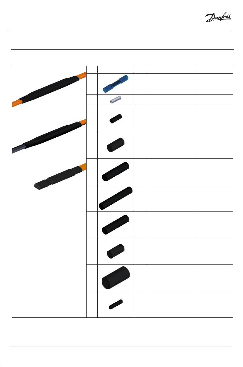
5 Kit contents
The following table lists the kit contents for the Danfoss heat shrink technology connection system:
No. Component Qty. Designation Dimensions
Bus wire splice lug
Heat shrink technology
connection system for
Danfoss PX / RX trace heaters
1 3 x
2 4 x Ferrule -
3 4 x
4 2 x
5 1 x
6 1 x
7 1 x
8 1 x
9 1 x
10 2 x
with heat shrink
tube
Heat shrink tube for
bus wires
Outer heat shrink
tube for bus wires
Connection covering
heat shrink tube
Final covering heat
shrink tube
Outer protection
heat shrink tube
Heat shrink tube for
end-termination
Outer heat shrink
tube for end-termi-
nation
Protection heat
shrink tube for
end-termination
-
Length:
1 3/8" / 35 mm
Diameter:
3/16” / 4,8 mm
Length:
3/4” / 19 mm
Diameter:
3/8” / 9,5 mm
Length:
4 1/2” / 115 mm
Diameter:
1/2” / 12 mm
Length:
7” / 175 mm
Diameter:
3/4” / 19 mm
Length:
8" / 200 mm
Diameter
3/4" / 19 mm
Length:
3/4” / 19 mm
Diameter:
1/2” / 12 mm
Length:
3 1/8" / 80 mm
Diameter:
3/4” / 19 mm
Length:
2 3/8” / 60 mm
Diameter:
3/4” / 19 mm
AN396730292442en-US0103
© Danfoss | 2022.02 | 5
Page 6
Installation Instruction
6 Installation
Cable to cable Splice - Heat shrink technology connection system
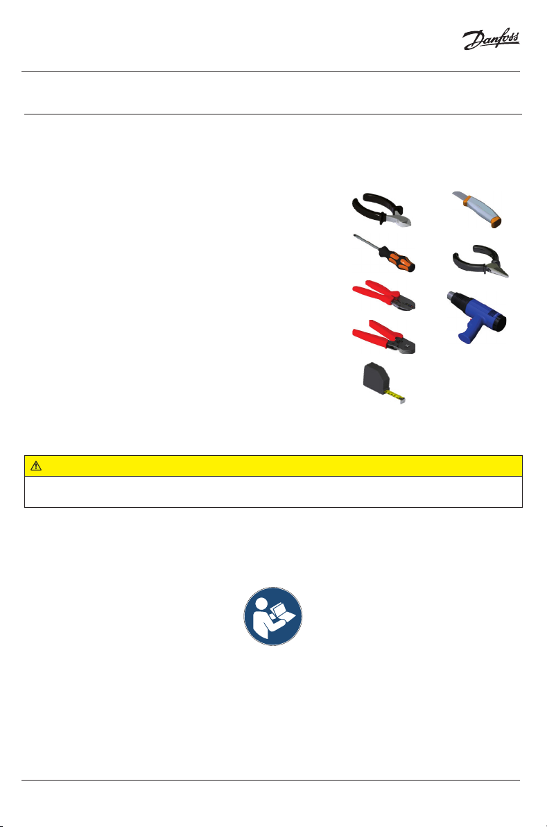
Required tools / equipment
The following tools and equipment are required for installation of the connection system:
• Wire cutters
• Flat screwdriver
• Crimping pliers 97 52 37 KNIPEX or equivalent
• Square-crimp crimping pliers
• Tape measure
• Utility knife
• Needle-nose pliers (2x)
• Heat gun
2 x
Cautions and warnings
WARNING:
Risk of re or electrical shock. De-energize all power circuits before installation or servicing. Always
use ground fault equip-ment protection with the heat tracing system.
• Double-check that all power circuits are de-energized before you begin your work.
1
2
• Make sure that you do not exceed the maximum heating circuit length for the trace heater type you
use. Refer to the design guide of the heating system.
6 | © Danfoss | 2022.02
AN396730292442en-US0103
Page 7
Installation Instruction
Preparation of trace heaters
WARNING:
Risk of short cuts and/or material damage. Keep the trace heater ends dry before and during installation. Observe the design guide of the trace heating system.
Cable to cable Splice - Heat shrink technology connection system
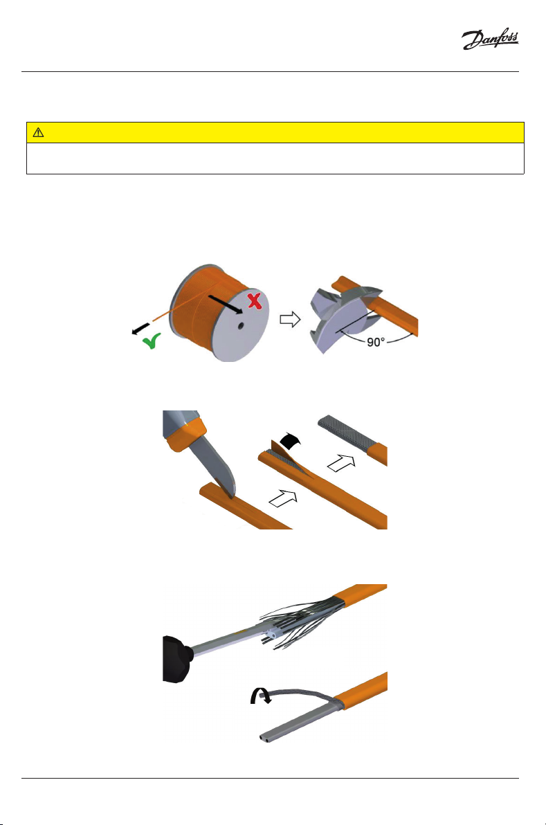
Unroll the required trace heater in a straight line and cut to the cor-rect length. Cut o the trace
heater ensuring a straight cut.
Do not bend or pinch the trace heater, or pull it over sharp edges.
Remove 2 3/8" (60 mm) of the outer jacket on the end of the trace heater.
Carefully separate the strands of the grounding braid of the insulation jacket.
Twist the grounding braid in order to form a pigtail.
3
4
5
AN396730292442en-US0103
© Danfoss | 2022.02 | 7
Page 8
Installation Instruction
Cable to cable Splice - Heat shrink technology connection system
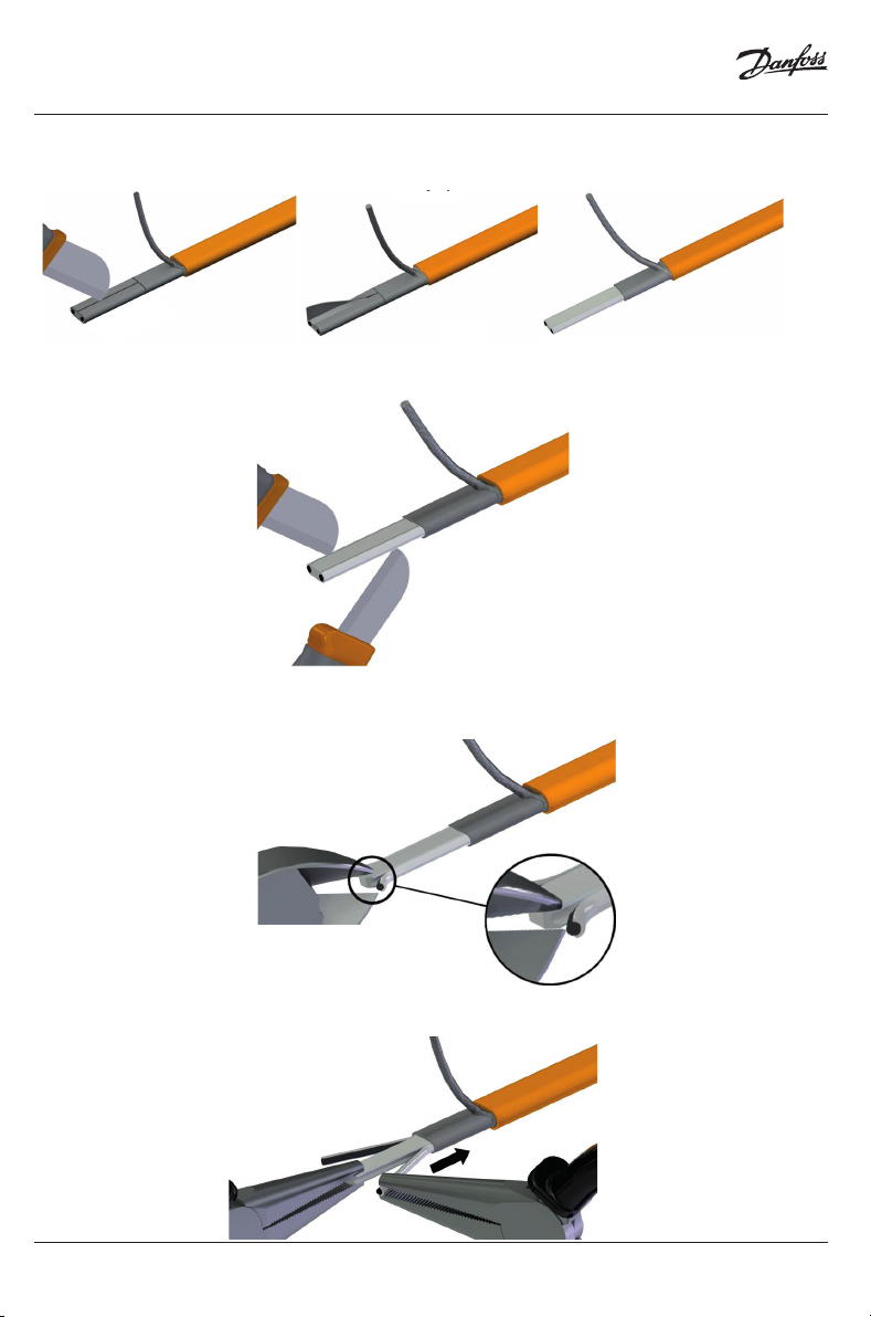
Remove 1 1/2" (40 mm) of the insulating jacket.
Make a small cut over and under each bus wire. Take care not to damage the bus wires.
Carefully make an incision into the edges of the heating matrix. Take care not to damage the bus
wires.
6
7
8
Pull o the bus wires while holding the heating matrix.
8 | © Danfoss | 2022.02
9
AN396730292442en-US0103
Page 9
Installation Instruction
Cable to cable Splice - Heat shrink technology connection system
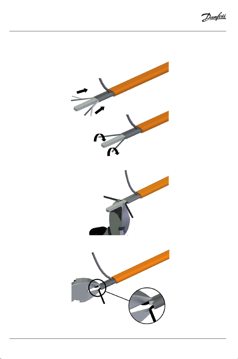
Remove any heating matrix that sticks to the bus wires.
Twist the bus wires.
Remove the remaining heating matrix. Take care not to damage the bus wires.
10
11
Cut in a triangle (¼” (5 mm)) between the bus wires.
AN396730292442en-US0103
12
© Danfoss | 2022.02 | 9
Page 10

Installation Instruction
Cable to cable Splice - Heat shrink technology connection system
CAUTION
Risk of burns. Beware of hot surfaces when using the heat gun.
ATTENTION
Risque de brûlures. Faites attention aux surfaces chaudes en utilisant le décapeur thermique.
Slide the bus wire heat shrink tubes (no. 4) all the way onto the bus wires.
Shrink the tubes at a temperature of 275 °F / 135 °C.
NOTICE
For acheiving a tube's temperature of 135 °C, the heat gun may be set to 250 °C setpoint (depends on
Manufacturer / Model) and may be held at a distance of approximately 10 mm to the heat shrink tubes.
Take care for moving circumferently to acheive perfect shrink process on the entire tubes.
All tubes are equipped with glue, which ist melt by the heat shrinking. Observe the glue is squeezing
out on both ends of the tubes and on full circumference.
:
:
13
14
Slide the outer heat shrink tube (no. 5) over the end of the trace heater.
Leave a gap of 1/4" (5 mm) to the outer jacket.
Shrink the tube at a temperature of 275 °F / 135 °C.
While still hot, compress the tube between the bus wires using pliers and hold for 5 seconds.
Repeat steps 3-14 for both trace heaters�
10 | © Danfoss | 2022.02
AN396730292442en-US0103
Page 11

Installation Instruction
Trace heater to trace heater connection
Slide the outer protection heat shrink tube (no. 8) the nal covering heat shrink tube (no. 7) and
the connection covering heat shrink tube (no. 6) onto the rst trace heater.
Cable to cable Splice - Heat shrink technology connection system
15
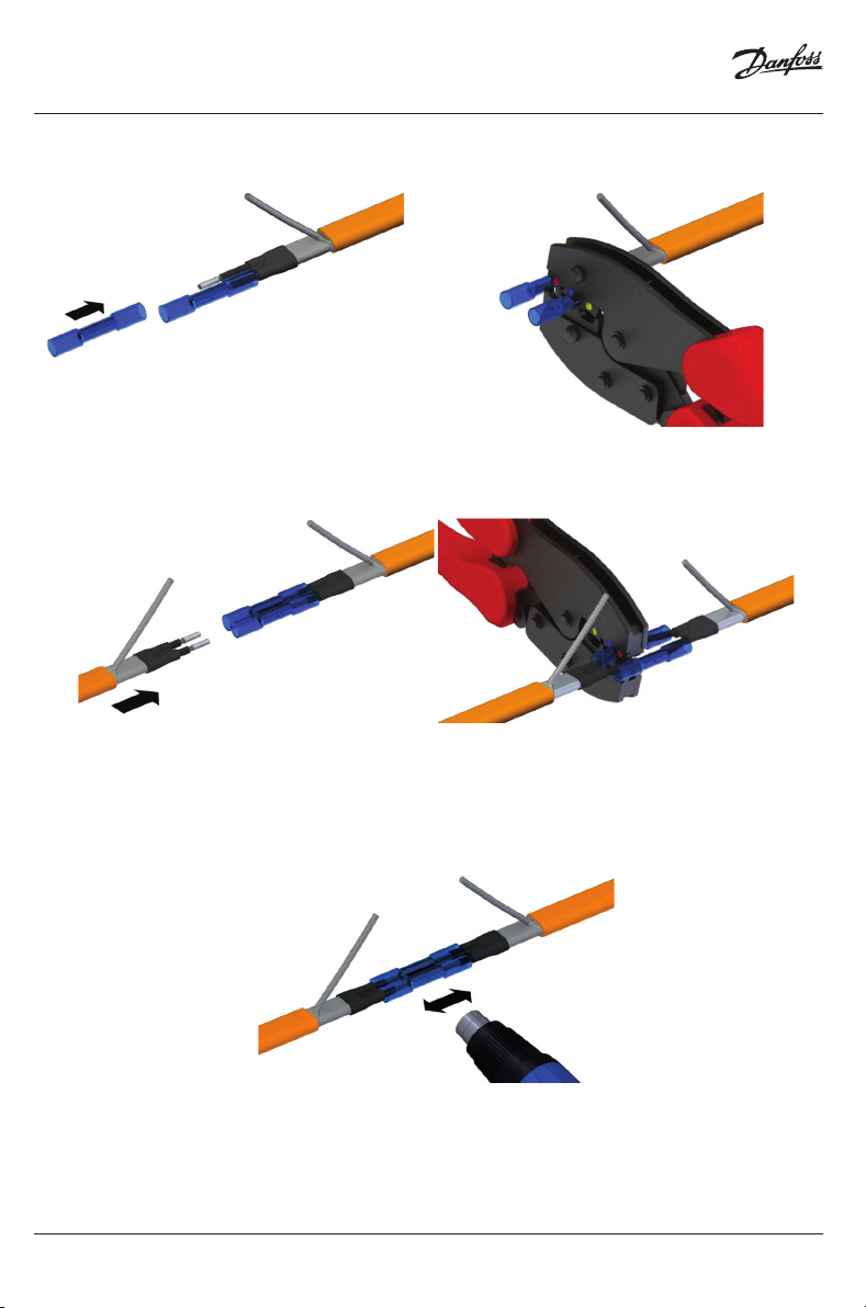
Slide a ferrule (no. 3) onto both of the bus wires.
Crimp on the ferrules using square-crimp crimping pliers.
16
17
Repeat steps 16-17 for both trace heaters�
AN396730292442en-US0103
© Danfoss | 2022.02 | 11
Page 12
Installation Instruction
Cable to cable Splice - Heat shrink technology connection system
Slide the bus wire splice lugs (no. 1) all the way onto the bus wires and crimp them on.
Now, slide the bus wires of the second trace heater all the way into the bus wire splice lugs
and crimp them on.
Shrink the red heat shrink tubes of the bus wire splice lugs at a temperature of 275 °F / 135 °C
until the adhesive oozes out.
If one of the outer heat shrink tubes (no. 5) opens up while shrinking, compress it again using pliers
and hold for 5 seconds.
18
19
20
12 | © Danfoss | 2022.02
AN396730292442en-US0103
Page 13

Installation Instruction
Cable to cable Splice - Heat shrink technology connection system
Slide the connection covering heat shrink tube (no. 6) onto the crimp connection. Make sure
to leave 3/8” / 10 mm of space between the heat shrink tube and the outer jacket.
Shrink the tube at a temperature of 275 °F / 135 °C.
Shorten the twisted shielding braid on both sides to 2 1/2" (65 mm).
21
22
AN396730292442en-US0103
© Danfoss | 2022.02 | 13
Page 14

Installation Instruction
Cable to cable Splice - Heat shrink technology connection system
Slide the splice lug (no. 1) all the way onto the twisted grounding braid of one of the trace
heaters.
Now, slide the twisted grounding braid of the other trace heater into the other end of the splice lug.
Crimp on the splice lug on both sides using the at crimping pliers.
Shrink the tube at a temperature of 275 °F / 135 °C.
Slide the nal covering heat shrink tube (no. 7) onto the connection.
Shrink the tube at a temperature of 275 °F / 135 °C.
Repeat the steps with the Outer protection heat shrink tube (no. 8)
23
24
14 | © Danfoss | 2022.02
AN396730292442en-US0103
Page 15

Installation Instruction
Preparation of the cold lead cable
Remove 3" (75 mm) of the outer jacket on the end of the cold lead cable.
Cable to cable Splice - Heat shrink technology connection system
3"
25
Remove 5/8" (15 mm) of the insulation of the bus wires and the grounding conductor.
5/8"
26
© Danfoss | 2022.02 | 15AN396730292442en-US0103
Page 16

Installation Instruction
Cold lead cable to trace heater connection
Slide the outer protection heat shrink tube (no.8) the nal covering heat shrink tube (no. 7)
and the connection covering heat shrink tube (no. 6) onto the trace heater.
Cable to cable Splice - Heat shrink technology connection system
27
Slide a ferrule (no. 3) onto both of the bus wires.
28
16 | © Danfoss | 2022.02
AN396730292442en-US0103
Page 17

Installation Instruction
Cable to cable Splice - Heat shrink technology connection system
Crimp on the ferrules using square-crimp crimping pliers.
Slide the bus wire splice lugs (no. 1) all the way onto the bus wires and crimp them on.
29
30
© Danfoss | 2022.02 | 17AN396730292442en-US0103
Page 18
Installation Instruction
Cable to cable Splice - Heat shrink technology connection system
Now, slide the bus wires of the cold lead cable all the way into the bus wire splice lugs and
crimp them on.
Shrink the blue heat shrink tubes of the bus wire splice lugs at a temperature of 275 °F / 135 °C
until the adhesive oozes out.
If the outer heat shrink tube (no. 5) opens up while shrinking, compress it again using pliers and hold
for 5 seconds.
Slide the connection covering heat shrink tube (no. 6) onto the crimp connection. Make sure to
leave ⁄” / 10 mm of space between the heat shrink tube’s ends and the outer jacket.
Shrink the tube at a temperature of 275 °F / 135 °C.
31
32
33
18 | © Danfoss | 2022.02
AN396730292442en-US0103
Page 19

Installation Instruction
Cable to cable Splice - Heat shrink technology connection system
Shorten the twisted shielding braid to 2 1/2" (65 mm).
2 1/2"
Slide the splice lug (no. 1) all the way onto the twisted grounding braid of one of the trace
heaters.
Now, slide the twisted grounding braid of the other trace heater into the other end of the splice lug.
Crimp on the splice lug on both sides using the at crimping pliers.
Shrink the tube at a temperature of 275 °F / 135 °C.
34
35
© Danfoss | 2022.02 | 19AN396730292442en-US0103
Page 20

Installation Instruction
Cable to cable Splice - Heat shrink technology connection system
Slide the nal covering heat shrink tube (no. 7) onto the connection.
Shrink the tube at a temperature of 275 °F / 135 °C.
Repeat the steps with the Outer protection heat shrink tube (no. 8).
36
20 | © Danfoss | 2022.02
AN396730292442en-US0103
Page 21

Installation Instruction
Cable to cable Splice - Heat shrink technology connection system
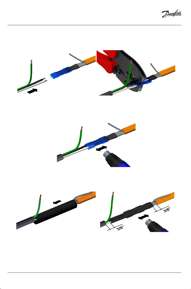
Installation of the end seal
Cut the trace heater o straight.
Remove 1 1/4" (30 mm) of the outer jacket on the trace heater.
37
Remove the exposed grounding braid. Make sure that the insulation jacket is not damaged.
Cut in a triangle (3/8" (5 mm)) between the bus wires.
Put the inner heat shrink tube for the end-termination (length: 3/4" (19 mm);
diameter: 1/2" (12 mm) over the end of the trace heater.
Leave an overlap of 3/8" (10 mm).
Beginning at the end of the cable, shrink the tube at a temperature of 275 °F / 135 °C.
38
39
© Danfoss | 2022.02 | 21AN396730292442en-US0103
Page 22

Installation Instruction
Cable to cable Splice - Heat shrink technology connection system
While still hot, compress the end of the tube using pliers and hold for 5 seconds.
NOTICE
For acheiving a tube's temperature of 135 °C, the heat gun may be set to 250 °C setpoint (depends
on Manufacturer / Model) and may be held at a distance of approximately 10 mm to the heat shrink
tubes. Take care for moving circumferently to acheive perfect shrink process on the entire tubes.
All tubes are equipped with glue, which ist melt by the heat shrinking. Observe the glue is squee-
zing out on both ends of the tubes and on full circumference.
Now, put the outer heat shrink tube (length: 3 1/8" (80 mm); diameter: 3/4" (19 mm)) over the end
of the trace heater.
Make sure that it overlaps the bared part of the trace heater for 3/4" (19 mm).
Beginning at the end of the cable, shrink the tube at a temperature of 275 °F / 135 °C.
Fold over the overlapping end of heat shrink tube 3/8" (10 mm).
Slightly press the end using pliers.
40
41
22 | © Danfoss | 2022.02
AN396730292442en-US0103
Page 23

Installation Instruction
Cable to cable Splice - Heat shrink technology connection system
Now, put the rst protection heat shrink tube (length: 2 1/3" (60 mm); diameter: 3/4" (19 mm)
over the end of the trace heater.
Leave a gap to the outer heat shrink tube of 3/4" (19 mm).
Beginning at the end of the trace heater, shrink the tube at a temperature of 275 °F / 135 °C.
Fold over the overlapping end of the heat shrink tube 3/8" (10 mm).
Slightly press the end using pliers.
Now, put the second protection heat shrink tube
(length: 2 1/3" (60 mm); diameter: 3/4" (19mm)) over the end of the trace heater.
Leave a gap to the very rst heat shrink tube of 3/8" (10 mm).
Beginning at the end of the trace heater, shrink the tube at a temperature of 275 °F / 135 °C.
42
© Danfoss | 2022.02 | 23AN396730292442en-US0103
Page 24

Installation Instruction
Cable to cable Splice - Heat shrink technology connection system
8 Troubleshooting
Problem Possible cause Remedy
Trace heater remains cold No power supply
Trace heater or cold lead cable not
properly connected
Control unit adjusted incorrectly
Automatic circuit breaker
disengages
Automatic circuit breaker
defective
Automatic circuit breaker has
wrong tripping characteristics,
e. g. “B” instead of “C”
Nominal circuit breaker size is
insucient
Maximum heating circuit length
has been exceeded
End seal has not been installed|
Short circuit
Humidity inside the connection
system or end seal
Ground fault protection
Trace heater damaged
is disengaged
Moisture in the junction box
Ground fault protection defective
Check the supply line
Connect the trace heater and
cold lead cable according to the
installation instructions
Adjust the control unit according
to the installation instructions
Replace the automatic circuit
breaker
Install an automatic circuit
breaker with Type-C tripping
characteristics
Install an automatic circuit breaker
with higher capacity (Observe
the maximum amperage of all
components of the trace heating
circuit!)
Split the heating circuit into
separate circuits
Install the end seal according to
the installation instructions
Identify the cause and remedy the
fault (e. g. ensure that tape tails are
not twisted)
Replace the connection system /
end seal
Replace the trace heater at the
point where it is damaged
Dry the junction box.
Be sure that the conduit drain is
installed and breathing properly
Replace the ground fault
protection device(s)
24 | © Danfoss | 2022.02
AN396730292442en-US0103
Page 25

Installation Instruction
Cable to cable Splice - Heat shrink technology connection system
9 Safety
For safe installation and operation of the cold applied connection system the technical requirements and instructions given
in this manual must be followed.
WARNING
Risk of re or electrical shock.Follow these guidelines to avoid personal injury or material damage.
• All electrical systems and installations must comply with Danfoss requirements and be installed in accordance with
the relevant electrical codes and any other applicable national and local codes.
• The US and Canadian electrical codes require ground fault protection to be provided for all trace heating circuits.
• Install the connection system and trace heaters carefully.
• Note that the design guide that comes with each trace heater contains further important information and must be
followed in addition to this manual.
• Use the trace heater and connection system in accordance with the intended purpose and strictly comply with the
operational data specied in section Technical Data.
• The bending radius of the trace heater must be at least 1” (25 mm).Do not bend on the narrow axis.
• Any defective component of the kit must be replaced before installation.
• To avoid short circuits, do not connect the trace heater bus wires together.
• Keep all components and the trace heaters dry before and during installation.
• Beware of hot surfaces when using the heat gun.
• Keep these instructions for future reference.If applicable, leave them with the end user.
• De-energize before installation or servicing.
• Use only original accessories.
Preparation of the trace heater
WARNING
Risk of re or electrical shock.De-energize all power circuits before installation or servicing. Always use ground fault
equipment within the heat tracing system.
• Double-check that all power circuits are de-energized before you begin your work.
• Make sure that you do not exceed the maximum heating circuit length for the trace heater type you
use.Refer to the system manual of the heating system.
WARNING
Risk of electrical shock and material damage.The gland body and grommet for PX/RX trace heaters are slightly dierent.
Make sure to use the cable gland kit that ts the trace heater you use.
WARNING
Risk of burns.Beware of hot surfaces when using the heat gun.
AN396730292442en-US0103
© Danfoss | 2022.02 | 25
Page 26

Installation Instruction
Cable to cable Splice - Heat shrink technology connection system
10 Sécurité et advertissements
An de garantir la sécurité lors de l’installation et de l’utilisation du système de connexion par tech nique de
thermorétraction Danfoss, il est impératif de respecter les exigences techniques ainsi que les consignes mentionnées dans
le présent manuel.
AVERTISSEMENT
Risque d’incendie ou d’électrocution. Suivez ces consignes pour éviter toute blessure ou dommage matériel.
• Tous les systèmes et installations électriques doivent satisfaire aux exigences imposées par la socié té Danfoss et
doivent être installés conformément aux normes électriques en vigueur ainsi qu’aux autres prescriptions nationales et
locales applicables.
• Les normes électriques américaines et canadiennes imposent une protection contre les défauts à la terre pour tous les
circuits de traçage électrique.
• La pose du système de connexion et des câbles chauants doit être réalisée avec le plus grand soin.
• Utilisez le câble chauant et le système de connexion adaptés à l’usage prévu et répondant aux caractéristiques de
fonctionnement spéciées à la section Caractéristiques techniques.
• Le rayon de courbure du câble chauant ne doit pas être inférieur à 1” (25 mm). Ne pas courber le câble chauant sur
la tranche.
• Tout élément défectueux dans le kit doit être remplacé avant l’installation.
• Pour éviter un court-circuit, ne jamais raccorder ensemble les deux conducteurs du câble chauant.
• Conservez tous les éléments et les câbles chauants au sec avant et pendant l’installation.
• Le câble de liaison froide doit être conforme aux exigences locales et être constitué de ls AWG 16 au minimum.
• Soyez prudent lors de l’utilisation du pistolet à air chaud, certaines surfaces peuvent devenir brû lantes.
• Chaque circuit chauant doit être clairement identié par un moyen permanent mentionnant le nom du fabricant, le
type de circuit, sa puissance et sa tension.
• N’employez jamais de ruban adhésif en vinyle, même en complément de ce kit.
• Conservez ces instructions pour un usage ultérieur. Le cas échéant, remettez-les à l’utilisateur nal.
• Mettre hors tension avant toute installation ou opération de maintenance.
• Utilisez exclusivement des pièces et accessoires d’origine Danfoss.
Avertissements et mises en garde
AVERTISSEMENT
Risque d’incendie ou de choc électrique. Éteignez tous les circuits d’alimentation avant l’installation ou l’entretien. Toujours
utiliser un équipement de défaut à la terre dans le système de traçage thermique.
• Vériez bien que tous les circuits électriques sont hors tension avant de débuter votre travail.
• Veillez à ne pas dépasser la longueur de circuit de traçage maximale autorisée pour le type de câble
chauant utilisé. Consultez à ce sujet le guide de conception du système de traçage.
AVERTISSEMENT
Risque d’électrocution et/ou de dommages matériels.Le corps du presse-étoupe et le passe-l destinés aux câbles
chauants PX/RX sont légèrement diérents.Prenez donc garde á bien utiliser le corps du presse-étoupe et le passe-l
adaptés au cäble chauant utilisé.
AVERTISSEMENT
Risque de brülure.Soyez prudent lors de l’utilisation du pistolet á ait chaud, certaines surfaces peuvent devenir brülantes.
26 | © Danfoss | 2022.02
AN396730292442en-US0103
Page 27

Installation Instruction
Cable to cable Splice - Heat shrink technology connection system
© Danfoss | 2022.02 | 27AN396730292442en-US0103
Page 28

Danfoss
11655 Crossroads Circle
Baltimore, MD 21220 USA
Phone: 1-888-DANFOSS (326-3677)
Fax: 416-352-59 81
lx.danfoss.com
28 | © Danfoss | 2022.02
088L8015 & AN396730292442en-US0103
 Loading...