

Page 1

MAKING MODERN LIVING POSSIBLE
Basic™ Heating Systems
DANFOSS HEATING SOLUTIONS Handbook
Page 2

Handbook Basic™ Heating Systems
2
VGCTB202 © Danfoss 10/2009
Page 3

Handbook Basic™ Heating Systems
Index
Page
Underfloor heating with heated screed as liquid or cement screed . . . . . . . . . . . . . . . . . . . . . 4
Basic heating systems . . . . . . . . . . . . . . . . . . . . . . . . . . . . . . . . . . . . . . . . . . . . . . . . . . 4
Advantages . . . . . . . . . . . . . . . . . . . . . . . . . . . . . . . . . . . . . . . . . . . . . . . . . . . . . . . . . 4
Relevant standards for underfloor heating . . . . . . . . . . . . . . . . . . . . . . . . . . . . . . . . . . . . . 5
Minimum thermal resistance of insulation
under floor heating systems from EN 1264, Part 4. . . . . . . . . . . . . . . . . . . . . . . . . . . . . . . . . 5
BasicRail . . . . . . . . . . . . . . . . . . . . . . . . . . . . . . . . . . . . . . . . . . . . . . . . . . . . . . . . . . . 5
BasicClip . . . . . . . . . . . . . . . . . . . . . . . . . . . . . . . . . . . . . . . . . . . . . . . . . . . . . . . . . . . 5
BasicGrip. . . . . . . . . . . . . . . . . . . . . . . . . . . . . . . . . . . . . . . . . . . . . . . . . . . . . . . . . . . 5
Basic insulation overlap panels. . . . . . . . . . . . . . . . . . . . . . . . . . . . . . . . . . . . . . . . . . . . . 6
Floor constructions . . . . . . . . . . . . . . . . . . . . . . . . . . . . . . . . . . . . . . . . . . . . . . . . . . . . 6
Thermal resistance . . . . . . . . . . . . . . . . . . . . . . . . . . . . . . . . . . . . . . . . . . . . . . . . . . . . 7
Basic perimeter insulation . . . . . . . . . . . . . . . . . . . . . . . . . . . . . . . . . . . . . . . . . . . . . . . . 8
Tanking for liquid screed. . . . . . . . . . . . . . . . . . . . . . . . . . . . . . . . . . . . . . . . . . . . . . . . . 8
BasicRail - types of installation . . . . . . . . . . . . . . . . . . . . . . . . . . . . . . . . . . . . . . . . . . . . 8
Application sheet - BasicRail, Room with floor meeting window. . . . . . . . . . . . . . . . . . . . . . . 9
BasicClip and BasicGrip - types of installation . . . . . . . . . . . . . . . . . . . . . . . . . . . . . . . . . . . 9
Application sheet - BasicClip, Conservatory . . . . . . . . . . . . . . . . . . . . . . . . . . . . . . . . . . . . 10
Application sheet - BasicGrip, Conservatory. . . . . . . . . . . . . . . . . . . . . . . . . . . . . . . . . . . . 11
Advice on installing BasicGrip . . . . . . . . . . . . . . . . . . . . . . . . . . . . . . . . . . . . . . . . . . . . . 12
Too ls . . . . . . . . . . . . . . . . . . . . . . . . . . . . . . . . . . . . . . . . . . . . . . . . . . . . . . . . . . . . . 13
Installation times . . . . . . . . . . . . . . . . . . . . . . . . . . . . . . . . . . . . . . . . . . . . . . . . . . . . . 14
Heated screed . . . . . . . . . . . . . . . . . . . . . . . . . . . . . . . . . . . . . . . . . . . . . . . . . . . . . . . 14
Danfoss screed additives . . . . . . . . . . . . . . . . . . . . . . . . . . . . . . . . . . . . . . . . . . . . . . . . 14
Installation . . . . . . . . . . . . . . . . . . . . . . . . . . . . . . . . . . . . . . . . . . . . . . . . . . . . . . . . . 15
Screed joints . . . . . . . . . . . . . . . . . . . . . . . . . . . . . . . . . . . . . . . . . . . . . . . . . . . . . . . . 15
Movement gap strips for BasicRail and BasicClip . . . . . . . . . . . . . . . . . . . . . . . . . . . . . . . . . 15
Important! Before and after installation of screed. . . . . . . . . . . . . . . . . . . . . . . . . . . . . . . . . .
16+Heating up screed . . . . . . . . . . . . . . . . . . . . . . . . . . . . . . . . . . . . . . . . . . . . . . . . . . 16
Active load and height of screed . . . . . . . . . . . . . . . . . . . . . . . . . . . . . . . . . . . . . . . . . . . 16
Categories of loaded areas, in accordance with EN 1991 . . . . . . . . . . . . . . . . . . . . . . . . . . . . 17
Minimum nominal thickness in mm for active loads in heated screed with Basic heating systems. . 17
After installation . . . . . . . . . . . . . . . . . . . . . . . . . . . . . . . . . . . . . . . . . . . . . . . . . . . . . . 17
Information for finished floors . . . . . . . . . . . . . . . . . . . . . . . . . . . . . . . . . . . . . . . . . . . . . 18
Thermal resistance R
of different finishes fully bonded to the floor . . . . . . . . . . . . . . . . 18
finished flo or
Output tables, BasicRail heating system . . . . . . . . . . . . . . . . . . . . . . . . . . . . . . . . . . . . . . . 19
Output tables, BasicClip and BasicGrip heating systems . . . . . . . . . . . . . . . . . . . . . . . . . . . . 27
VGCTB202 © Danfoss 10/2009
3
Page 4

Handbook Basic™ Heating Systems
Underfloor heating with
heated screed as liquid
or cement screed
Basic heating systems
Advantages
Underfloor heating, with its low supply temperature, has many advantages. It runs maintenancefree, is energy saving and ensures comfortable
room temperatures.
Rooms with underfloor heating allow greater
freedom for interior design. The Danfoss FH pipes
enclosed in cement or liquid screed give off
The Danfoss underfloor heating systems with
heated screed - Basic heating systems - are low
temperature underfloor heating systems suitable
for all new buildings. They can be installed in all
rooms and floors of blocks of flats or in business
premises.
The grey Danfoss composite pipes are installed,
according to worked out distances, using
BasicClip, BasicGrip or BasicRail on insulation
panels giving the pipe lay-out. The water flowing
though the composite or PE-RT pipes gently
warms the screed which works as heating
element. It is possible to lay all common floor
• Low energy saving temperature
• Cost eective, no additional costs
• 100% impervious to air, no heat exchanger
necessary
• Comfortable, clean and healthy air
• Greater freedom of interior design, more living
space for whole family
• Maintenance-free
comfortable warmth without any drafts, - creating
a dustfree, hygenic environment.
coverings on top of Danfoss underfloor heating,
except perhaps heavy exotic carpets or special
engineered wood flooring which would need
extra calculations when planning the system.
Since low water temperatures are required to
achieve the required room temperatures, Danfoss
underfloor heating systems are ideal for use with
boilers, solar energy and heat pumps. This means
that producers of energy saving heat will find an
ideal partner in underfloor heating.
Relevant standards for
underfloor heating
The following regulations and EN Standards
should be observed when planning and installing
floor heating:
EN 1991 Action on structures
EN 1264 Underfloor Heating, Systems and
Components
DIN 4109 Sound Insulation in the Building
Industry
ISO EN 140-8 Measurement of sound insulation
in buildings and building elements
EN 13813 Screed Material and Floor Screeds
Local building regulations.
Professional information on interface co-ordination
when planning heated underfloor construction
(ref: BVF).
For underfloor heating the EN 1264, part 4
standards are applicable.
Three Danfoss basic constructions are possible:
A, B and C.
They meet the minimum insulation requirements
in relation to use and position in the house.
4
VGCTB202 © Danfoss 10/2009
Page 5

Handbook Basic™ Heating Systems
Minimum thermal
resistance of insulation
under floor heating
systems from EN 1264,
part4
BasicRail
Construction A B C
Heated room
below
Thermal
resistance
(m K/W)
* When groundwater table is < 5 m this value should be raised!
The composite pipes are clipped onto the BasicRail
self-adhesive clip rails at regular distances.
The maximum of 2 m between the clip rails should
only be applied when using cement screed.
When using liquid screed a maximum distance of
1m should be observed. Because of the fluid
consistency of liquid screed it could run under
the pipes and can push them upwards.
0.75 1.2 5 1.2 5 1.5 2
Unheated or
occasionally
heated room
below or
room on
ground floor*
Outside air temperature below construction
Design
outside
temperature
Td > 0° C
In accordance with EN 1264 Danfoss FH pipes
should be laid more than
• 50 mm away from vertical construction, such as
walls
• 200 mm from chimneys and open re places,
open and walled-up shafts, as well as lift shafts
Design
outside
temperature
0° C > Td ≥ -5° C
Design
outside
temperature
-5° C > Td ≥ -15° C
BasicClip
BasicGrip
The BasicClip System is a tacker system where the
pipes are tacked onto the insulation with u-shaped
tacker pins. The insulation overlap panels are
supplied as 2 x 1 m pre-folded panels. The foil
clad panels give a perfect grip for the barbs in
the EPS and under the foil.
The grid pattern on the panel foil is 50 mm which
allows the different laying distances to be kept :
100 and 150 mm for Edge Zones, and 200, 250
and 300 mm for Comfort Zones.
Any additional insulation should be laid under
the BasicClip overlap panels.
The BasicGrip panel system consists of deeply
drawn foil with studs that allow perfect laying of
pipes.
With their size of 1 x 1 m, the panels are easy to
lay and can be installed by just one person.
The panels can be cut with the usual cutter knife.
The studded panels facilitate correct pipe
distances. Laying the pipes diagonally is possible
without additional grips. It is safe to walk on the
strong foam studded panels.
When using the BasicGrip panel without thermal
insulation the deeply drawn foil is correspondingly
thicker.
The laying distance is calculated in multiples of
50 mm, so that possible pipe distances in the
Edge Zone are 100 and 150 mm and in the
Comfort Zone 200, 250 and 300 mm are achieved.
Any additional insulation should be laid under
the BasicGrip panels.
BasicClip insulation overlap panels are available
in 2 variations:
• with 35 mm thermal and impact sound
insulation EPS
• with 20 mm thermal and impact sound
insulation EPS
For optimum installation of the system an
expansion profile is available to overcome
expansion gaps and door thresholds.
The system is suitable for liquid (CAF) and
cement screeds (CT).
BasicGrip panels are available in 3 variations:
• with 35 mm thermal and impact sound
insulation EPS
• with 11 mm thermal insulation EPS
• without insulation
For optimum installation of the system, the
following additional products are on offer:
• An expansion prole to overcome expansion
gaps and door thresholds
• Door and manifold panels with varying
insulation thickness
• PE –String to seal perimeter insulation when
using liquid screed
The system is suitable for liquid (CAF) and
cement screeds (CT).
VGCTB202 © Danfoss 10/2009
5
Page 6

Handbook Basic™ Heating Systems
Basic insulation overlap
panels
Floor constructions
The individual components of the overlap
insulation panels are bonded and consist of the
Continuous sound impact insulation also has to
be installed.
following layers:
• Bonded multi-layer foil with 5 cm grids to
facilitate exact pipe laying
• A thermal and impact sound insulation layer
made of polystyrene
What type of insulation is used, depends on the
type of floor and the building. If the concrete is
even and free of other installations, a single layer
of insulation is sucient. In 90% of all new
buildings heating, sanitation and electrical
services are installed which require double layer
insulation.
For height adjustment, thermal insulation, e.g.
EPS 035 DEO 20 mm is laid between the pipe
channels and gaps around the pipes are filled
with Danfoss Dry Levelling Compound.
Finally, the Basic insulation overlap panels are
installed. The surface of these 2 m2 (1 + 1 m2
foldable) insulation panels are very strong, safe
to walk on, and form a very good surface for
BasicClip and BasicRail heating systems.
The strong foil is a technically perfect base for
cement and liquid screeds.
A: Floor construction above rooms of equal use/ temperature; Minimum thermal resistance
R
= 0.75 m2K/W
min
Construction with insulation panels 20/35 mm plus additional insulation:
Insulation panels 20/35 mm
R = 0.44 m2K/W; R = 0.77 m2K/W
20 20 20 20 35 35 35 35 mm
+ + + + + + + +
EPS DEO λ =0.040 W/mK 20 - mm
EPS DEO λ=0.035 W/mK 20 - mm
PUR λ=0.030 W/mK 20 - mm
PUR λ =0.025 W/mK 20 - mm
Total thermal resistance R 0.94 1.01 1. 11 1.27 0.77 0.77 0.77 0.77 m K/W
Total insulation thickness 40 40 40 40 35 35 35 35 mm
B: Floor construction above occasionally or permanently unheated rooms, cellars or ground-
floor (ground water table > 5 m); minimum thermal resistance R
= 1.25 m2 K/W
min
Construction with insulation panels 20/35 mm plus additional insulation :
Insulation 20/35 mm
R = 0.44 m2K/W; R = 0.77 m2K/W
20 20 20 20 35 35 35 35 mm
+ + + + + + + +
EPS DEO λ = 0.040 W/mK 40 20 mm
EPS DEO λ = 0.035 W/mK 30 20 mm
PUR λ = 0 .030 W/mK 30 20 mm
PUR λ = 0.025 W/mK 30 20 mm
Total thermal resistance R 1.4 4 1. 30 1.44 1.6 4 1.27 1.34 1.43 1.57 m K/W
Total insulation thickness 60 50 50 50 55 55 55 55 mm
C: Construction for floors against outside air; minimum thermal resistance R
= 2.0 m2 K/W
min
Construction with insulation panels 20/35 mm plus additional insulation:
Insulation 20/35 mm
R = 0.44 m2K/W; R = 0.77 m2K/W
20 20 20 20 35 35 35 35 mm
+ + + + + + + +
EPS DEO λ = 0.040 W/mK 70 50 mm
EPS DEO λ = 0.035 W/mK 60 50 mm
PUR λ = 0 .030 W/mK 50 40 mm
PUR λ = 0.025 W/mK 40 40 mm
Total thermal resistance R 2 .19 2 .16 2 .11 2.04 2.02 2.2 2.1 2.37 m K/W
Total insulation thickness 90 80 70 60 85 85 75 75 mm
λ = Thermal conductivity in W/mK.
6
VGCTB202 © Danfoss 10/2009
Page 7

Handbook Basic™ Heating Systems
Thermal resistance
R
Insulation
Insulation thickness in (mm)
Thermal resistance in (W/mK)
[
d
=
λ
Other combinations are possible to achieve
certain built-up heights. The following table
indicates the thermal resistance of the different
insulations, dependent on their thickness.
EPS 045 DES EPS 040 DEO EPS 035 DEO PUR λ = 0.03
Thickness
[mm]
10 0.22 10 0.25 10 0.29 10 0.33 10 0.40
]
15 0.33 15 0.38 15 0.43 15 0.50 15 0.60
20 0.44 20 0.50 20 0. 57 20 0.67 20 0.80
25 0.56 25 0.63 25 0.71 25 0.83 25 1. 00
30 0. 67 30 0.75 30 0.86 30 1.00 30 1. 20
35 0.78 35 0.88 35 1.0 0 35 1.17 35 1. 40
40 0.89 40 1. 00 40 1 .14 40 1. 33 40 1. 60
45 1. 00 45 1.13 45 1. 29 45 1. 50 45 1. 80
50 1 .11 50 1. 25 50 1.43 50 1.67 50 2.00
55 1.2 2 55 1. 38 55 1. 57 55 1.8 3 55 2.20
60 1. 33 60 1. 50 60 1.7 1 60 2.00 60 2.40
65 1. 44 65 1. 63 65 1. 86 65 2 .17 65 2.60
70 1. 56 70 1.75 70 2.00 70 2.33 70 2.80
75 1.67 75 1. 88 75 2 .14 75 2.50 75 3.00
80 1.78 80 2.00 80 2.29 80 2.67 80 3.20
85 1. 89 85 2.13 85 2.43 85 2.83 85 3.40
90 2.00 90 2.25 90 2.57 90 3.00 90 3.60
95 2 .11 95 2.38 95 2.71 95 3 .17 95 3.80
100 2.22 100 2.50 100 2.86 100 3.33 10 0 4.00
105 2.33 105 2.63 105 3.00 105 3.50 10 5 4.20
110 2.44 11 0 2.75 11 0 3.14 110 3.67 11 0 4.40
115 2.56 115 2.88 115 3.29 115 3.83 115 4.60
120 2.67 120 3.00 120 3.43 120 4.00 120 4.80
125 2.78 125 3.13 125 3.57 125 4.17 125 5.00
130 2.89 130 3.25 130 3 .71 13 0 4. 33 130 5.20
135 3.00 135 3.38 135 3.86 135 4.50 135 5.40
140 3. 11 140 3.50 14 0 4.00 14 0 4.67 140 5.60
145 3.22 145 3.63 145 4 .14 145 4.83 145 5.80
150 3. 33 150 3.75 150 4.29 15 0 5.00 15 0 6.00
155 3.44 155 3.88 155 4.43 155 5 .17 155 6.20
160 3.56 16 0 4.00 16 0 4.57 16 0 5.33 160 6.40
165 3.67 165 4.13 165 4.71 165 5.50 165 6.60
170 3.78 170 4.25 170 4.86 17 0 5.67 17 0 6.80
175 3.89 17 5 4.38 17 5 5.00 175 5.83 175 7. 00
180 4.00 18 0 4.50 18 0 5.14 180 6.00 180 7. 2 0
185 4. 11 18 5 4.63 185 5.29 185 6 .17 18 5 7. 4 0
190 4.22 190 4.75 190 5.43 190 6. 33 190 7. 6 0
195 4.33 195 4.88 19 5 5.57 195 6.50 19 5 7. 80
200 4.44 200 5.00 200 5.71 200 6.67 200 8.00
R
insulation
[m K/W ]
Thickness
[mm]
R
[m K/W ]
insulation
Thickness
[mm]
The final layer should always be the Basic
insulation overlap panels 20/35 mm to guarantee
a stable base for further installation.
W/mK PUR λ = 0.025 W/mK
R
[m K/W ]
insulation
Thickness
[mm]
R
insulation
[m K/W ]
Thickness
[mm]
R
insulation
[m K/W ]
VGCTB202 © Danfoss 10/2009
7
Page 8

Handbook Basic™ Heating Systems
Basic perimeter
insulation
Tanking for
liquid screed
BasicRail
- types of installation
The Basic Perimeter insulation 150 mm consists of
8 mm PE-Foam. The double-sided adhesive tape
on the back allows it to be easily attached to the
wall. The adhesive tape on the room side of the
foil attaches the perimeter insulation to the
insulation panels.
In accordance with EN 1264 the perimeter
insulation can be compressed by 5 mm and thus,
When using liquid screed the insulation joints
should be taped over to accept screed with a
very thin consistency.
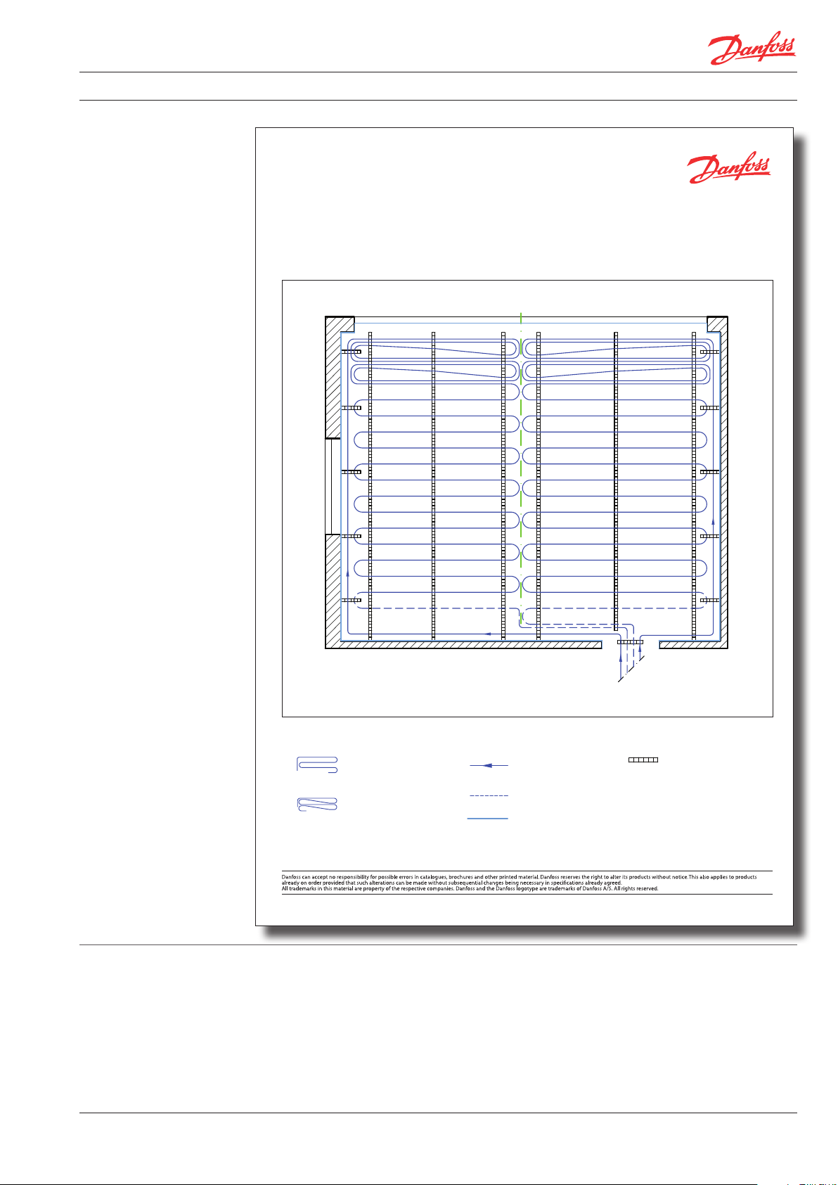
The heating circuits are laid in meander form,
which is an advantage when first installing the
pipes in the edge zones of the room (Edge Zone)
and then taking them to the centre of the room
(Comfort Zone): the warmer temperatures of the
heating circuit arrive at the outer zones (higher
floor temperature), and the cooled down water
heats the central zone (lower floor temperature).
together with the insulation panels, forms the
required tank for the screed as well as thermal
and sound bridges.
When using a double layer of insulation, the
additional insulation should be laid first. Should
their thickness exceed 5 cm, the perimeter
insulation is installed on top of the additional
insulation.
To achieve higher output around the edges or in
front of windows, you can lay the pipes in double
pattern.
Please see recommended layout patterns in
Danfoss application sheets.
8
VGCTB202 © Danfoss 10/2009
Page 9
Handbook Basic™ Heating Systems
Legend
FH Composite pipe
CC CZ 2 = 250 mm
Flow
BasicRail
Distances bet ween rails:
Liquid screed 1.00 m
Cement screed 1.50 - 2.0 0 m
FH Composite pipe
CC EZ 1 = 88 mm
Return
Perimeter insulation
Application Sheet
BasicRail
Room with floor meeting window
Danfoss HES VA.CT.H1.02 © Danfoss 11/2008 1
Heating circuit 1
Heating circuit 2
Application sheet
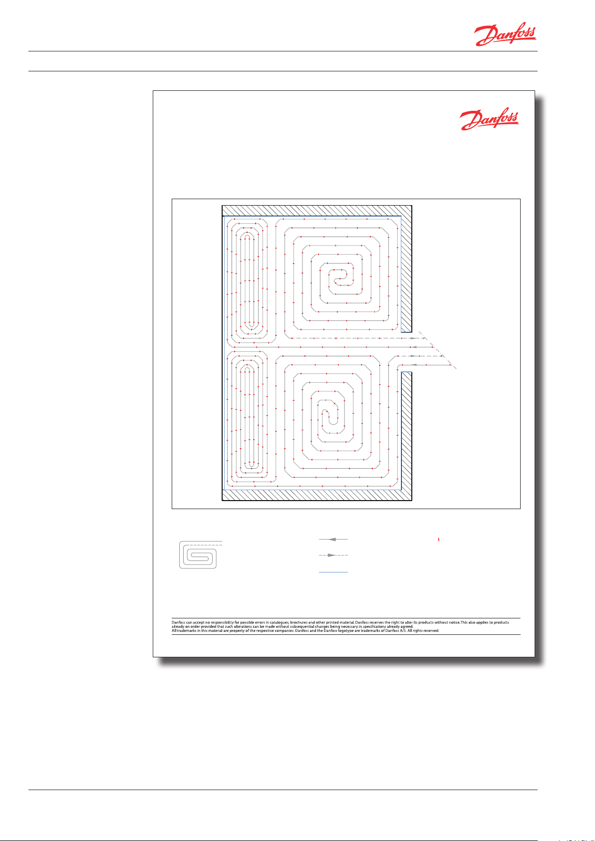
BasicClip and BasicGrip
- types of installation
The Danfoss wet systems BasicGrip and BasicClip
are laid in spiral form.
The Danfoss composite pipe is laid in spiral form
starting from the edge, leading to the centre of
the room. The pipe distance is twice that of the
calculated pipe spacing. The pipe is then led out
of the centre between the installed pipes.
The advantage is that pipes of higher temperature are next to those of lower temperature, thus
VGCTB202 © Danfoss 10/2009
producing an even surface temperature (higher
output).
Edge Zone: if a higher heat output is required,
the pipes in the Edge Zone (up to 1 m from wall)
can be laid closer, thus producing a higher
surface temperature.
9
Page 10
Handbook Basic™ Heating Systems
Legend
Pipe layout EZ 100
CC = 100 mm
Supply BasicClip clip,
2 clips per meter
Return
Pipe layout CZ 200
CC = 200 mm
Perimeter insulation
Application Sheet
BasicClip
Conservatory
Danfoss HES VA.EK.B1.02 © Dan foss 11/2008 1
Heating circuit 1
Heating circuit 2
Application sheet
10
VGCTB202 © Danfoss 10/2009
Page 11
Handbook Basic™ Heating Systems
Legend
Pipe layout EZ 100
CC = 100 mm
Supply BasicGrip panel
Size: 1 x 1 m
Return
Pipe layout CZ 200
CC = 200 mm
Perimeter insulation
Application Sheet
BasicGrip
Conservatory
Danfoss HES VA.EL. A1.02 © Danfoss 11/2008 1
Heating circuit 1
Heating circuit 2
Application sheet
VGCTB202 © Danfoss 10/2009
11
Page 12

Handbook Basic™ Heating Systems
A B C D E G H1
H2 I J K L
- Floor Construction
Advice on installing
BasicGrip
1: Begin installing in left hand corner. In order to
achieve a tight join at the wall, cut off both
overlaps on the first BasicGrip panel.
2: For panels B to G, cut off overlaps against the
wall.
Cut off overlaps
3: Shorten H1 according to room calculations and
also cut off overlap on wall side.
4: Start the next row with the remaining part (H2).
12
VGCTB202 © Danfoss 10/2009
Page 13

Handbook Basic™ Heating Systems
- Floor Construction
Tools
Pipe cutter
Danfoss pipe cutter incl. corrugated pipe
cutter for trimming the Danfoss composite
pipes 16 x 2.00 / 20 x 2.25 mm and the Danfoss
protective pipe.
Pipe cutter
Danfoss universal pipe cutter for trimming
composite pipes up to 32 x 3.00 mm and the
Danfoss clip rail.
Bevelling tool
Danfoss bevelling tool for calibrating and
bevelling the Danfoss composite pipes.
The handle is removable, so the tool can be
attached to rechargeable drills (< 500 r/min).
Dimensions of 16 - 20 mm allow inner and outer
bevels which facilitates installation
Pipe bending springs
Danfoss pipe bending springs are able to form
radiuses of up to 4 x D.
Press tool
Danfoss press tool is, together with the inserts,
suitable for pressing of Danfoss composite
pipes with dimensions of 16 and 20 mm.
Pipe dispensing wheel
Danfoss pipe dispensing wheel is indispensable
for one-man installations. It holds the coiled
pipe, is compact and easy to transport, and will
fit into narrow spaces.
Measurement base
Points marked out to measure the residual
moisture in the screed without damaging the
pipes.
VGCTB202 © Danfoss 10/2009
13
Page 14

Handbook Basic™ Heating Systems
Installation times
Heated screed
Installation Times for Basic Heating Systems *
Article / Unit
Installation of manifold without cabinet 55.00 Unit
Installation of manifold with cabinet 75.00 Unit
Installation of additional insulation without perimeter insulation, each layer 2.50 m
Installation of insulation overlap panels 20 mm / 35 mm incl. perimeter insulation 2.50 m
C-C = 88 mm type of installation 1 (pipe layout, connection to manifold) 11. 3 0 m
C-C = 120 mm type of installation 2 (pipe layout, connection to manifold) 8.40 m
C-C = 200 mm type of installation 1 (pipe layout, connection to manifold) 5.00 m
C-C = 250 mm type of installation 2 (pipe layout, connection to manifold) 4.00 m
C-C = 300 mm type of installation 3 (pipe layout, connection to manifold) 3.50 m
* 06/2004 Values based on practical experience.
Only heated screed should be used. The Danfoss
screed additive should be used when installing
cement screed. The screed additive Normal CT F4
has the effect of increasing thermal conductivity
as well as allowing the screed to retain more heat.
Both contribute to an even distribution of heat
within the room and guarantee better resistance
to pressure and more flexibility.
Liquid screed should be prepared as heated
screed. To achieve a very thin cement screed, the
Danfoss Screed Additive Special should be used.
It achieves an even better resistance to pressure
and more flexibility, as well as a higher thermal
conductivity.
Mastic asphalt is not suitable for Basic underfloor
heating systems. The outer sleeve of the
composite pipe is not resistant to the higher
temperatures of this form of screed.
The mean heating water temperature must not
exceed 55˚ C when using cement and Anhydrite
screeds.
Minutes
per unit
Unit
Danfoss screed additives
14
Normal:
The screed additive is added to the screed and
not the water.
• Required quantity per m2: 215 g
• Height of heated screed: 70 mm
• Screed quality: CT F4
• Volume of can: 10 kg
Mixing cement screed in connection with
underfloor heating.
Mortar-mix:
• 50 kg cement CEM I 32.5 R
• 250 kg gravel sand 0/8 mm (approx. 30-36
shovels full)
• 16-18 litres water
• 500 g (0.5 litre) Danfoss screed additive
Mixing instructions using a forced action mixer:
• 10 shovels full of gravel sand (approx. 30 litres)
• 50 kg cement CEM I 32.5 R
• 10 litres water
• 0.5 litres Danfoss screed additive
• 20-26 shovels full of gravel sand (approx. 110
litres)
• 6-8 litres water
• Mortar consistency of moist soil to malleable,
minimum mixing time 1 min.
VGCTB202 © Danfoss 10/2009
Special:
The screed additive Special is suitable when low
height screed is required. This synthetically
modified additive is added by the specialist
screeder.
• Required quantity per m2: 1820 g
• Height of heated screed: 65 mm
• Screed quality: CTF 5
• Volume of can: 10 kg
Page 15

Handbook Basic™ Heating Systems
10 m
2
10 m
2
40 m
2
10 m
2
15 m
2
30 m
2
Installation
Screed joints
Fresh screed mortar should be poured along the
length of the composite pipes and should be well
tamped. It must be protected from frost.
Screed should be installed at room temperatures
of above 5° C, and any draft should be avoided.
Fix certain points as measuring point to ascertain
residual moisture.
Floating screeds expand and contract depending
on temperature, particularly heated screeds. To
compensate for this, screed is divided into
geometric fields. The perimeter insulation allows
for some of the expansion, and movement gap
strips between the fields allow for movement
and avoid cracks (5 mm minimum expansion).
Movement gaps have to be allowed for on room
edges and between large and multi-angular
areas (e.g. L- or Z-shaped). The proportion of
width to length should not exceed 1:2.
Joints in the building should be mirrored in the
screed. The size of the areas should not exceed
40 m2 with a maximum length of 8 m.
Unusual area shapes exposed to higher temperatures tend to crack easily, so careful planning of
expansion joints is advisable.
The type of finished floor also determines the
layout of the screed areas. Screed temperature is
higher when carpet is laid but with tiles the
difference in temperature between upper and
lower surface of the screed is significantly higher,
which means these constructions tend to crack
more easily.
When composite pipes cross a screed joint, the
pipes should be protected with a movement gap
strip against expansion and shear stress.
This occurs when two adjacent screed slabs move
towards each other (expansion, buckling of the
embedded pipes), or move across each other
(shearing), or even do both.
There should be no heating pipes within a
distance of 10 cm (Ø20 cm) around that point.
The 40 cm long pipe sleeves absorb any movement of the screed and the composite pipe
remains permanently protected.
Movement gap strips for
BasicRail and BasicClip
Basic movement gap strip consists of a 2 m
long movement gap strips to install joints with
double-sided adhesive strip and a 100 mm high
The sleeves are pushed into the profile and
appropriate holes for the pipe channels are cut
into the movement joint.
perimeter insulation strip.
Pipe sleeves
• 40 cm long
• to protect crossing pipes
Installation
Before pouring the screed, the movement gap
strips are installed. The movement gap strips are
first attached to the given positions on the plan
(in agreement with the screeder and floor finisher).
They are attached to the insulation using the
double-sided tape. Afterwards a section of
perimeter insulation is inserted into the slot.
Pipes going through the movement joint should
be protected with an outer sleeve.
VGCTB202 © Danfoss 10/2009
15
Page 16

Handbook Basic™ Heating Systems
Important!
Before and after
installation of screed
• Heated screed is installed after pipe layout, insulations and joint gap strips are fixed.
• Before the screed is installed the building/room
must be completely plastered, windows and
doors must be firmly closed to avoid the screed
drying too fast and thus possibly causing cracks
or even other damage in the building.
• Before screeding, check again that screed areas
and heating circuits are co-ordinated and the
movement gap joints are not interrupted. If the
Danfoss composite pipes cross movement joints
they should be protected.
• When screeding, the pipes must be under
pressure so that possible problems are noticed
and can be rectified.
• Screed should be installed at temperatures
above 5° C (risk of frost).
Table to show when to lay the finished floor (according to moisture content)
Finished floor
Ceramic tiles or thickbed
natural-/ concrete stones thinbed
Textile finish vapour permeable
e.g. carpet vapour proof
Elastic finishes e.g. PVC, Linoleum, rubber 1.8 % 0.3 %
• Should a sudden unexpected frost occur after
screeding, care must be taken not to let the
temperature fall below 5° C. If it is possible to
turn on the Danfoss underfloor heating the flow
temperature must not exceed 25° C.
• Heating up should follow the Danfoss heating
up protocol. It is important to check the residual
moisture before laying the finished floor; this
would be done by the professional laying the
finished floor.
• The perimeter insulation remains in place and is
only cut to the appropriate height after the floor
is finished.
Approved moisture
content when cement
screed is used
3.0 % not applicable
2.0 % 0.3 %
3.0 % 1.0 %
1.8 % 0.3 %
Approved moisture
content when Anhydrite
screed is used
Heating up of screed
Active load and
height of screed
Engineered timber floor, laminates 1.8 % 0.3 %
The heating up of the screed should be carried
out according to the Heating Up Protocol.
After 7 days it is possible to walk on the cement
screed, but only after 21 days should the heating
up take place.
For Anhydride or Calcium Sulphate based screed
heating up can begin after 7 days, or according to
manufacturers’ recommendation. During heating
up, the automatic control should be off and the
supply temperature should be adjusted manually. All joints should be checked and any solid
matter should be removed from the joints. For
the first three days, the flow temperature should
be kept at 25° C, after that the maximum supply
temperature should be run for four days, and the
heating circuits should be turned off. While
cooling down the heated screed should be
protected from draft and rapid cooling. The
Depending on use, the floor construction will
have to meet different demands. These are
defined in EN 1991: Action on Structures.
floorer should now measure the residual
moisture and decide whether the final floor can
be laid.
It must be noted here, that during the first year,
because of residual moisture in new buildings,
the heating temperature should be higher than
normal. This additional moisture should dry out
during the first heating period. The heating up
process does not guarantee to achieve the
required moisture level of the screed. An
additional heating up operation may be necessary to establish whether the final floor can be
laid.
Commissioning of the underfloor heating after
the floor has been finished should be decided by
the final flooring firm.
16
VGCTB202 © Danfoss 10/2009
Page 17

Handbook Basic™ Heating Systems
Categories of
loaded areas,
in accordance
with EN 1991
The Danfoss construction sheets describe the
approved type of use. Depending on active and
constructions other than home and office
buildings.
point load, EN 1991 is also applicable for
qK
Category Use Examples
A1
Areas for
domestic and
A2 Stairs 2.0 - 4.0 2.0 - 4.0
residential
activities
A3 Balconies 2.5 - 4.0 2.0 - 3.0
B Office areas 2.0 - 3.0 1.5 - 4.5
C1
C2
Areas where
people may
congregate
(with the
C3
exception of
areas defined
under category
A, B, D)
C4
C5
D1
Shopping areas
D2 Areas in department stores 4.0 - 5.0 3.5 - 7. 0
Floors 1.5 - 2.0 2.0 - 3.0
Areas with tables , e.g. areas in schools, cafés, restaurants,
dining halls, reading rooms, receptions
Areas with fixed seats, e.g. areas in churches, theatres or
cinemas, conference rooms, lecture halls, assembly halls,
waiting rooms, railway waiting rooms
Areas without obstacles for moving people, e.g. areas in
museums, exhibition rooms etc. and access areas in public
administration buildings, hotels, hospitals, railway station
forecour ts
Areas with possible physical activities, e.g. dance halls,
gymnastic rooms, stages
Areas susceptible to large crowds, e.g. in buildings for
public events like concert halls, sports halls including
stands, terraces and access areas and railway platforms
Areas in general retail shops 4.0 - 5.0
(Active
load)
kN/m
2.0 - 3.0 3.0 - 4.0
3.0 - 4.0
3.0 - 5.0 4.0 - 7.0
4.5 - 5.0 3.5 - 7. 0
5.0 - 7.5 3.5 - 4.5
QK
(Point
load)
kN
2.5 - 7.0
(note 3)
3.5 - 7.0
(note 3)
Minimum nominal
thickness in mm for
active loads in heated
screed with Basic
heating systems
After installation
Note 1: Depending on their anticipated uses, areas likely to be categorised as C2, C3, C4 may be categorised as C5 by
decision of the client and/or National annex.
Note 2: The National annex may provide sub categories to A, B, C1 to C5, D1 and D2.
Note 3: Recommended values are highlighted. For categories C2 and D1 the recommended value is 4.0.
Different active loads are accomodated in the
thickness of the heated screed.
< 2 kN/m < 3 kN/m 5 kN/m
Point load below
2 kN/m
CT F4 with screed additive Normal 65 85 90 95
CAF F4 60 70 80 85
CT F5 with screed additive Special 60* 75 80 85
CAF F5 50* 65 70 75
Compactibility of insulation: max. 5 mm max. 3 mm.
Point load below
3 kN/m
Point load below
4 kN/m
*For insulation thickness < 40 mm the screed can be reduced by 5 mm .
When the installation is completed the individual
heating circuits are filled with water via the fill
and drain on the manifold.
The pressure test follows, which in winter can
also be done with pressurised air.
The project manager/architect is ready to sign
the hand-over protocol.
the manufacturer’s information needs to be
followed).
After starting the heat source, the individual heat
circuits are set via the valves.
Then the actuators are screwed onto the return
valves and connected via the Danfoss wiring
centre to the room thermostats.
Now the screed has to be installed quickly and
heated up according to protocol (for liquid screed
VGCTB202 © Danfoss 10/2009
17
Page 18

Handbook Basic™ Heating Systems
Information for
finished floors
The following floor finishes can be laid on
underfloor heating if they meet the thermal
resistance requirements of R
are approved by the manufacturer :
≤ 0.15 m2 K/W and
λ,B
• Ceramic tiles
• Natural worked stone
• Elastic nishes (PVC)
• Textile nishes (carpets)
• Engineered timber oor and laminates
It is important to adhere to the manufacturers'
advice.
The adhesives for stone tiles or ceramic finishes
used in the the thinbed method must be
appropriate for underfloor heating and for the
load bearing.
If the floor is laid using the thickbed method, the
heating up and response times are much greater
due to a higher build up.
Elastic and textile floor finishes should be fully
glued down. When laying textile floor finishes, it
is possible to use adhesives that allow a later
removal of the floor.
Natural products, such as engineered timber
floors or other timber products, adjust to their
environment which can cause contraction. This
does not mean a faulty floor. Depending on the
wood, expansion and contraction vary, but this
can be minimised by keeping an even temperature.
When installing engineered timber floors or
laminates, the thermal resistance data should be
provided as well as data for possible air gaps and
additional carpets.
It may be necessary to fill gaps between dry floor
elements before laying the finished floor.
Thermal resistance
R
finished floor
finishes fully bonded
of different
to the floor
Finished floor surface Thermal resistance: R
Natural stone 0.009
Ceramic tiles 0.01
PVC 0. 012
Linoleum 0. 015
Mosaic engineered timber - oak 0.044
Cork 0.062
Standard EN-1264 value 0.10 0
Carpet 0.10 8
Strip flooring - oak 0.122
Laminates 0.044
Multi-layer engineered timber (Parquett) 0.050 - 0.080
Maximum recommendation 0.15 0
[m K/W]
λ,B
18
VGCTB202 © Danfoss 10/2009
Page 19

Handbook Basic™ Heating Systems
Output table,
BasicRail heating
systems
Thermal resistance of the finished floor covering:
R
m2 K/W 0.00 (e.g. tiles).
λ,B
Differential temperature (σ K) 5.
Heat output on the basis of EN 1264.
Cement screed
Room
C-C 8.8
Mean heating
water temperature
θ
m
temperature
θ
i
Cement screed
θ
C-C 12
Surface
temperature
F
Cement screed
θ
VA 20
Surface
temperature
F
Cement screed
θ
VA 25
Surface
temperature
F
Cement screed
θ
°C °C W/m °C W/m °C W/m °C W/m °C W/m °C
30 15 101. 0 24 .1 92 .1 23.4 73.6 21.8 63.9 21.0 55.7 20.3
30 18 80.4 25.4 73.3 24.8 58.5 23.5 50.8 22.9 44.3 22.3
30 20 66.6 26.2 60.7 25.7 48.5 24 .7 42.1 24 .1 36.7 23.6
30 22 52.6 27. 0 47. 9 26.6 38.3 25.8 33.2 25.3 29.0 24.9
30 24 38.3 2 7.8 34.9 2 7. 5 27. 9 26.8 24.2 26.5 2 1.1 26.2
35 15 13 5. 3 26.8 123 .4 25.9 98.5 23.9 85.6 22.8 74. 6 21.9
35 18 11 4. 8 28.2 10 4.6 2 7.4 83.5 25.6 72.6 24.7 63.3 23.9
35 20 101.0 29 .1 92 .1 28.4 73.6 26.8 63.9 26.0 55.7 25.3
35 22 8 7. 3 30.0 79.6 29.3 63.5 28.0 55.2 2 7. 2 48 .1 26.6
35 24 73.5 30.8 67. 0 30.3 53.5 29 .1 46.5 28.5 40.5 28.0
40 15 169. 4 29.5 15 4.5 28.4 12 3. 3 25.9 10 7.1 24.6 93.4 23.5
40 18 149.0 30.9 135 .8 29.9 108 .4 2 7.7 94.2 26.5 82 .1 25.5
40 20 135 .3 31. 8 12 3. 4 30.9 98.5 28.9 85.6 27. 8 74. 6 26.9
40 22 121 .6 32.7 110 . 9 31.9 88.5 30.1 76.9 2 9.1 67. 1 28.3
40 24 107. 9 33.6 98.4 32.9 78.6 31. 2 68.2 30.4 59.5 29.6
45 15 203.5 32.2 18 5.6 30.8 14 8. 2 27. 9 12 8. 7 26.3 112 . 2 25.0
45 18 18 3.1 33.6 166 .9 32.3 13 3.3 29.7 115 . 8 28.3 101.0 2 7.1
45 20 16 9.4 34.5 15 4. 5 33.4 123 . 3 30.9 1 07. 1 29.6 93.4 28.5
45 22 15 5.8 35.5 142 .0 34.4 113 . 4 3 2.1 98.5 30.9 85.9 29.8
45 24 142 .1 36.4 129 .6 35.4 103. 5 33. 3 89.9 32.2 78.4 31. 2
50 15 2 3 7.6 34.8 216. 6 33.2 173 .0 29.8 150 .2 28.0 131 .0 26.5
50 18 2 17. 2 36.2 19 8. 0 34.7 15 8.1 31.6 1 37. 3 30.0 119 . 8 28.6
50 20 203.5 3 7. 2 18 5.6 35.8 14 8. 2 32.9 12 8. 7 31.3 112 . 2 30.0
50 22 18 9.9 3 8.1 17 3.1 36.8 138 .2 34 .1 12 0.1 32.6 104 .7 31.4
50 24 176 .3 39 .1 160 .7 37. 8 12 8. 3 35.3 111. 5 33.9 97. 2 32.8
55 15 2 71.6 3 7. 3 2 47. 7 35.5 19 7.7 31.7 171. 8 29.7 149 .8 28.0
55 18 251. 2 38.8 22 9.1 37.1 182. 9 33.6 158 .9 31.7 138 .5 30 .1
55 20 23 7. 6 39. 8 216 .6 38.2 173 .0 34.8 15 0. 2 33.0 13 1.0 31. 5
55 22 224.0 40.7 204.2 39. 2 163 .0 36.0 141. 6 34.3 12 3. 5 32.9
55 24 210. 3 41.7 191. 8 40.3 153 .1 37. 3 13 3.0 35.7 11 6 .0 34.3
VA 30
Surface
temperature
F
Surface
temperature
Cement screed
θ
F
Maximum floor surface temperature in accordance with EN 1264: Edge Zone 1.00 m
Comfort Zone
Bathrooms
VGCTB202 © Danfoss 10/2009
35 °C
29 °C
33 °C
19
Page 20

Handbook Basic™ Heating Systems
- Installation
Output table,
BasicRail heating
systems
Thermal resistance of the finished floor covering:
R
m2 K/W 0.00 (e.g. tiles).
λ,B
Differential temperature (σ K) 5.
Heat output on the basis of EN 1264.
Liquid Screed
Room
C-C 8.8
Mean heating
temperature
Liquid screed
C-C 12
Surface
temperature
Liquid screed
VA 20
Surface
temperature
Liquid screed
VA 25
Surface
temperature
Liquid screed
water temperature
θ
θ
m
i
θ
F
θ
F
θ
F
θ
°C °C W/m °C W/m °C W/m °C W/m °C W/m °C
30 15 117.1 25.4 10 6.4 24.5 84.3 22.7 73.0 21.8 63.2 20.9
30 18 93. 2 26.4 84.7 25.7 67. 0 24.3 5 8.1 23.5 50.3 22.8
30 20 7 7.1 27.1 70.1 26.5 55.5 25.3 48 .1 24.6 41. 6 2 4.1
30 22 60.9 2 7.7 55.4 2 7.3 43.8 26.3 38.0 25.7 32.9 25.3
30 24 44.4 28.3 40.3 27. 9 32.0 2 7. 2 27. 7 26.8 23.9 26.5
35 15 15 6. 8 28.5 142 .5 2 7.4 112. 8 25.0 9 7. 7 23.8 84.6 22.7
35 18 13 3.0 29.7 12 0. 8 28.7 95.7 26.6 82.9 25.6 71.7 24.7
35 20 11 7.1 30.4 106 .4 29.5 84.3 27. 7 73.0 26.8 63.2 25.9
35 22 101.2 31.1 91.9 30.3 72.8 28.7 63.0 2 7.9 54.6 27. 2
35 24 85.2 31.8 77. 4 31 .1 61. 3 29.8 5 3.1 2 9.1 45.9 28.4
40 15 196 .3 31. 6 178 .4 30.2 141. 3 2 7. 3 12 2. 3 25.8 105.9 24.5
40 18 172.6 32.8 15 6. 8 31 .5 12 4. 2 29.0 1 07. 6 27. 6 93.1 26.4
40 20 156 .8 33. 5 142 .5 32.4 112 . 8 30.0 9 7.7 28.8 84.6 27. 7
40 22 140 .9 34.3 12 8. 0 33.3 101. 4 31.1 8 7. 8 30.0 76. 0 29.0
40 24 12 5. 0 35.0 11 3. 6 3 4.1 90.0 32.2 77. 9 31.2 67. 4 30.3
45 15 235.9 34.6 214 .3 33.0 169.7 29.6 147. 0 27. 8 12 7. 2 26.2
45 18 212 .2 35.8 192 .8 34.3 152 .7 31.2 132 .2 29.6 114 . 4 28.2
45 20 19 6. 3 36.6 178 .4 35.2 141. 3 32 .3 12 2. 3 30.8 10 5.9 29.5
45 22 18 0.5 3 7. 4 16 4.0 3 6.1 129 .9 33.4 112 . 5 32.0 9 7.4 30.8
45 24 164. 7 38.2 149 .6 3 7. 0 118 . 5 34.5 102.6 33.2 88.8 3 2.1
50 15 275.3 3 7. 6 250.2 35.7 19 8.1 31.7 17 1.6 29.7 148 .5 2 7. 9
50 18 251. 6 38.8 228.7 3 7.1 181.1 33.4 156 .8 31. 5 135. 7 29.9
50 20 235.9 39.6 214 .3 38.0 169. 7 34.6 1 47. 0 32.8 12 7. 2 31. 2
50 22 220.1 40.4 19 9.9 38.9 15 8. 3 35.7 13 7.1 34.0 118 . 7 32.5
50 24 204.2 41.2 185 .6 39.8 14 7.0 36.8 12 7. 3 35. 2 11 0. 2 33.8
55 15 314 .8 40.5 286.0 38.4 226.5 33.9 19 6.1 31.6 169. 8 29.6
55 18 2 91.1 41. 8 264.5 39.8 209. 5 35.6 181. 4 33.5 15 7.0 31.6
55 20 275.3 42.6 250.2 40.7 19 8.1 36.7 17 1.6 34.7 148 .5 32.9
55 22 259.5 43.4 235. 8 41. 6 186 .8 3 7.9 161.7 35.9 140 .0 34.2
55 24 243.7 44.2 2 21.5 42. 5 17 5.4 39.0 151.9 3 7. 2 131. 5 35.5
VA 30
Surface
temperature
F
Surface
temperature
Liquid screed
θ
F
20
Maximum floor surface temperature in accordance with EN 1264: Edge Zone 1.00 m
Comfort Zone
Bathrooms
VGCTB202 © Danfoss 10/2009
35 °C
29 °C
33 °C
Page 21

Handbook Basic™ Heating Systems
Output table,
BasicRail heating
systems
Thermal resistance of the finished floor covering:
R
m2 K/W 0.05 (e.g. engineered timber floor /
λ,B
synthetic fibre).
Differential temperature (σ K) 5.
Heat output on the basis of EN 1264.
Liquid Screed
Room
C-C 8.8
Mean heating
temperature
Liquid screed
C-C 12
Surface
temperature
Liquid screed
VA 20
Surface
temperature
Liquid screed
VA 25
Surface
temperature
Liquid screed
water temperature
θ
θ
m
i
θ
F
θ
F
θ
F
θ
°C °C W/m °C W/m °C W/m °C W/m °C W/m °C
30 15 81. 7 22.5 75.5 22.0 62.3 20.8 55.0 20.2 48.7 19.7
30 18 65.0 24 .1 60 .1 23.7 49.5 22.8 43.8 22.2 38.8 21.8
30 20 53.8 2 5.1 49.7 24.8 41. 0 24.0 36.2 23.6 32.1 23.2
30 22 42.5 2 6.1 39.3 25.8 32.4 25.2 28.6 24.9 25.4 24.6
30 24 31. 0 2 7.1 28.6 26.9 23.6 26.4 20.8 26.2 18. 5 25.9
35 15 10 9.4 24.8 101.1 24 .1 83.4 22.6 73.6 21.8 65.3 21.1
35 18 92.8 26.4 85.7 25.8 70.7 24.6 62.4 23.9 55.4 23.3
35 20 81. 7 27. 5 75.5 27. 0 62.3 25.8 55.0 25.2 48.7 24.7
35 22 70.6 28.6 65.2 28 .1 53.8 27.1 47. 5 26.6 42 .1 26 .1
35 24 59. 4 29.6 54.9 29.2 45.3 28.4 40.0 2 7.9 35.4 2 7. 5
40 15 1 37. 0 2 7. 0 12 6. 6 26 .1 104 .4 24.4 92.2 23.4 81.7 22.5
40 18 120. 5 28.7 111 . 3 2 7. 9 91.8 26.3 81.0 25.4 71. 8 24.7
40 20 109. 4 29. 8 101.1 2 9.1 83.4 2 7. 6 73.6 26.8 65.3 26 .1
40 22 98.4 30.9 90.8 30.2 74.9 28.9 66.2 28.2 58.7 27. 5
40 24 8 7. 3 32.0 80.6 31.4 66.5 30.2 58.7 29.5 52 .1 29.0
45 15 16 4.6 29.2 15 2.0 28.2 125 .4 26 .1 11 0. 7 24.9 98.2 23.8
45 18 14 8.1 30.9 13 6. 8 30.0 112 . 8 28.0 99.6 2 7.0 88.3 26.0
45 20 13 7.0 32.0 12 6. 6 31.1 10 4.4 29.4 92.2 28.4 81.7 2 7. 5
45 22 12 6. 0 33 .1 11 6. 4 32. 3 96.0 30.7 84.8 29.7 75 .1 28.9
45 24 115 . 0 34.2 10 6.2 33.5 8 7. 6 32 .0 77. 3 31.1 68.6 30.4
50 15 192 .2 31 .3 1 77. 5 30.2 146 .4 2 7. 7 129. 3 26.4 114 . 6 25.2
50 18 175 .6 33.0 162 .2 32.0 133 .8 29.7 11 8. 2 28.5 104 .7 27. 4
50 20 16 4.6 34.2 15 2. 0 33.2 12 5.4 3 1.1 11 0 .7 29.9 98.2 28.8
50 22 15 3.6 35.3 141.9 34.4 117. 0 32.4 103. 3 31.3 91.6 30.3
50 24 142.6 36.4 131. 7 35.6 108 .6 33.7 95.9 32.7 85.0 31. 8
55 15 219.7 33.4 202.9 3 2.1 16 7. 4 29.4 147. 8 27. 8 131. 0 26.5
55 18 203.2 35 .1 1 87. 7 33.9 15 4. 8 31.4 136 .7 30.0 121. 2 28.7
55 20 19 2. 2 36.3 17 7. 5 35.2 14 6.4 32.7 12 9. 3 31.4 11 4. 6 30.2
55 22 181.2 3 7.4 167. 3 36.4 138 .0 34 .1 12 1.9 32.8 108 .0 31.7
55 24 17 0.1 38.6 1 57.1 37. 6 12 9. 6 35.4 11 4. 5 34.2 101.5 3 3.1
VA 30
Surface
temperature
F
Surface
temperature
Liquid screed
θ
F
Maximum floor surface temperature in accordance with EN 1264: Edge Zone 1.00 m
Comfort Zone
Bathrooms
VGCTB202 © Danfoss 10/2009
35 °C
29 °C
33 °C
21
Page 22

Handbook Basic™ Heating Systems
Output table,
BasicRail heating
systems
Thermal resistance of the finished floor covering:
R
m2 K/W 0.05 (e.g. engineered timber floor /
λ,B
synthetic fibre).
Differential temperature (σ K) 5.
Heat output on the basis of EN 1264.
Cement screed
Room
C-C 8.8
Mean heating
water temperature
θ
m
temperature
θ
i
Cement screed
θ
C-C 12
Surface
temperature
F
Cement screed
θ
VA 20
Surface
temperature
F
Cement screed
θ
VA 25
Surface
temperature
F
Cement screed
θ
°C °C W/m °C W/m °C W/m °C W/m °C W/m °C
30 15 73.3 21.8 67. 8 21. 3 56.2 20.3 49.9 19.8 44.4 19 .3
30 18 58.3 23.5 53.9 23 .1 44.7 22.3 39.7 21.9 35.4 21.5
30 20 48.3 24.6 44.6 24. 3 37. 0 23.6 32.9 23.3 29.3 22.9
30 22 38 .1 25.7 35.3 25.5 29.2 24.9 26.0 24.6 2 3.1 24.4
30 24 2 7. 8 26.8 25.7 26.6 21.3 26.2 18.9 26.0 16. 8 25.8
35 15 9 8.1 23.8 90.7 23.2 75. 2 21.9 66.8 21.2 59.5 20.6
35 18 83.2 25.6 77. 0 2 5.1 63.8 24.0 56.7 23.4 50.5 22.8
35 20 73.3 26.8 6 7.8 26.3 56.2 25.3 49.9 24.8 44.4 24.3
35 22 63.3 2 7.9 58.5 2 7. 5 48.5 26.7 43 .1 26.2 38.4 25.8
35 24 53. 3 29.1 49. 3 28.7 40.9 28.0 36.3 27. 6 32.3 2 7. 2
40 15 122 .8 25.8 113 . 6 2 5.1 94.2 23.5 83.7 22.7 74. 5 21.9
40 18 10 8.0 2 7. 6 99.9 2 7.0 82.8 25.6 73.6 24.8 65.5 24 .1
40 20 98 .1 28.8 90.7 28.2 75.2 26.9 66.8 26.2 59.5 25.6
40 22 88.2 30.0 81.5 29.5 67. 6 28.3 60 .1 2 7.7 53.5 2 7.1
40 24 78.2 31.2 72.4 30.7 60.0 29.7 53.3 29 .1 4 7.4 28.6
45 15 147. 6 2 7. 8 13 6. 5 26.9 113 .1 2 5.1 10 0.6 24.0 89. 5 2 3.1
45 18 132 .7 29.6 12 2. 8 28.8 101.8 2 7.1 90.5 26.2 80.5 25.4
45 20 12 2. 8 30.8 113 . 6 30 .1 94.2 28.5 83.7 27. 7 74. 5 26.9
45 22 112 .9 32 .0 104 .5 31. 4 86.6 29.9 7 7. 0 29 .1 68.5 28.4
45 24 103.0 33.2 95.3 32.6 79.0 31. 3 70.2 30.5 62.5 29.9
50 15 17 2. 3 29.8 15 9.3 28.7 132 .1 26.6 11 7.4 25.4 10 4.5 24.4
50 18 1 57. 4 31. 6 145 .6 30.7 120 .7 28.7 1 07. 3 27. 6 95.5 26.6
50 20 147. 6 32.8 136 .5 31.9 113 .1 3 0.1 10 0.6 29.0 89.5 28 .1
50 22 137. 7 34.0 12 7. 3 33.2 105 .6 31. 5 93.8 30.5 83.5 29.6
50 24 12 7. 8 35. 2 11 8. 2 34.5 98.0 32. 8 87.1 31.9 7 7. 5 31.1
55 15 19 6.9 31.7 182 .2 30.5 151.0 28 .1 134 .2 26.8 11 9. 4 25.6
55 18 18 2.1 33.5 168 .5 32.5 13 9.6 30.2 124 .1 29.0 11 0. 5 27. 8
55 20 17 2. 3 34.8 159 .3 33.7 13 2.1 31.6 117. 4 30.4 10 4.5 29.4
55 22 16 2.4 36.0 150 .2 35.0 124 .5 33.0 11 0 .7 31.9 98.5 30.9
55 24 152 .5 37. 2 141.1 36.3 116 . 9 34.4 103 .9 33.3 92.5 32.4
VA 30
Surface
temperature
F
Surface
temperature
Cement screed
θ
F
22
Maximum floor surface temperature in accordance with EN 1264: Edge Zone 1.00 m
Comfort Zone
Bathrooms
VGCTB202 © Danfoss 10/2009
35 °C
29 °C
33 °C
Page 23

Handbook Basic™ Heating Systems
Output table,
BasicRail heating
systems
Thermal resistance of the finished floor covering:
R
m2 K/W 0.10 (e.g. carpet).
λ,B
Differential temperature (σ K) 5.
Heat output on the basis of EN 1264.
Liquid screed
Room
C-C 8.8
Mean heating
temperature
Liquid screed
C-C 12
Surface
temperature
Liquid screed
VA 20
Surface
temperature
Liquid screed
VA 25
Surface
temperature
Liquid screed
water temperature
θ
θ
m
i
θ
F
θ
F
θ
F
θ
°C °C W/m °C W/m °C W/m °C W/m °C W/m °C
30 15 62.7 20.9 58.7 20.5 49.8 19. 8 44.9 19. 3 40.6 19.0
30 18 49.9 22.8 46.7 22.5 39.6 21. 9 35.7 21.5 32.3 21.2
30 20 41. 3 24.0 38.7 23.8 32 .8 23.3 29.6 23.0 26.7 22.7
30 22 32.6 25.3 30.5 25 .1 25.9 24.6 23.4 24.4 21.1 24.2
30 24 23.8 26.4 22.3 26.3 18.9 26.0 17. 0 25.8 15. 4 25.6
35 15 84.0 22.7 78.6 22.2 66.6 21.2 60 .1 20.7 54.3 20.2
35 18 71. 2 24.6 66.7 24.2 56.5 23.4 51.0 22.9 4 6.1 22.4
35 20 62.7 25.9 58.7 25.5 49.8 24.8 44.9 24.3 40.6 24.0
35 22 54.2 27. 2 50.7 26.9 43.0 26.2 38.8 25.8 35.0 25.5
35 24 45.6 28.4 42.7 28.2 36.2 27. 6 32.6 27. 3 29.5 2 7. 0
40 15 10 5.1 24.4 98.4 23.9 83.5 22.6 75.2 21. 9 68.0 21. 3
40 18 92.4 26.4 86.5 25.9 73.4 24.8 66.2 24.2 59.8 23.6
40 20 84.0 27. 7 78.6 27. 2 66.6 26.2 60 .1 25.7 54.3 25.2
40 22 75.5 29.0 70.6 28.6 59.9 2 7. 6 54.0 2 7.1 48.8 26.7
40 24 67. 0 30.2 62.7 29.9 53.2 2 9.1 4 7.9 28.6 43.3 28.2
45 15 12 6. 3 26 .1 11 8. 2 25.5 100 .3 24.0 90.4 23.2 81.7 22.5
45 18 11 3. 6 2 8.1 10 6.3 2 7. 5 90.2 26.2 81.3 25.5 73.5 24.8
45 20 105 .1 29.4 98.4 28.9 83.5 27. 6 75.2 26.9 68.0 26.3
45 22 96.7 30.7 90.5 30.2 76.7 2 9.1 69.2 28.4 62.5 2 7.9
45 24 88.2 32.0 82.6 31. 6 70.0 30.5 63 .1 29.9 57.1 29.4
50 15 147. 4 2 7. 8 13 8. 0 2 7.1 117. 1 25.4 105 .5 24.4 95.4 23.6
50 18 134 .8 29.8 12 6.1 2 9.1 10 7.0 27. 6 96.4 26.7 8 7. 2 25.9
50 20 12 6. 3 31 .1 11 8. 2 30.5 100. 3 29.0 90.4 28.2 81.7 27. 5
50 22 117. 8 32.4 11 0. 3 31.8 93.6 30.5 84.3 29.7 76. 2 29.0
50 24 109.4 33.8 102 .4 33.2 86.8 31.9 78.3 31.2 70.8 30.6
55 15 16 8.6 29.5 15 7. 8 28.6 133. 8 26.7 12 0. 6 25.7 10 9.1 24.7
55 18 15 5.9 31. 5 145.9 30.7 12 3. 8 28.9 111. 6 27. 9 100.9 27. 1
55 20 14 7.4 32.8 138 .0 32 .1 117.1 30.4 10 5.5 29.4 95.4 28.6
55 22 139. 0 3 4.1 13 0.1 33.4 11 0 . 3 31 .8 99.5 31.0 89.9 30.2
55 24 130 .5 35. 5 122 . 2 34.8 103. 6 33. 3 93.4 32.5 84.4 31.7
VA 30
Surface
temperature
F
Surface
temperature
Liquid screed
θ
F
Maximum floor surface temperature in accordance with EN 1264: Edge Zone 1.00 m
Comfort Zone
Bathrooms
VGCTB202 © Danfoss 10/2009
35 °C
29 °C
33 °C
23
Page 24

Handbook Basic™ Heating Systems
Output table,
BasicRail heating
systems
Thermal resistance of the finished floor covering:
R
m2 K/W 0.10 (e.g. carpet).
λ,B
Differential temperature (σ K) 5.
Heat output on the basis of EN 1264.
Cement screed
Room
C-C 8.8
Mean heating
water temperature
θ
m
temperature
θ
i
Cement screed
θ
C-C 12
Surface
temperature
F
Cement screed
θ
VA 20
Surface
temperature
F
Cement screed
θ
VA 25
Surface
temperature
F
Cement screed
θ
°C °C W/m °C W/m °C W/m °C W/m °C W/m °C
30 15 5 7. 7 20.5 53.9 20 .1 46 .1 19. 4 41. 8 19.1 3 7. 7 18 .7
30 18 45.9 22.4 42.9 22.2 36.7 21. 6 33.2 21.3 30.0 21. 0
30 20 38.0 23.7 35.5 23.5 30.3 23.0 2 7. 5 22.8 24.9 22.5
30 22 30.0 25.0 28 .1 24.8 24.0 24. 5 21. 7 24.2 19. 6 24.0
30 24 21. 9 26.3 20.5 26.1 17. 5 25.8 15. 8 25.7 14. 3 25.5
35 15 7 7. 2 22 .1 72.2 21.7 61 .7 20.8 55.9 20.3 50.5 19.8
35 18 65.5 24 .1 61. 3 23.8 52.3 23.0 47. 4 22.6 42 .9 22.2
35 20 5 7. 7 25.5 53.9 25 .1 46 .1 24.4 41. 8 2 4.1 37. 7 23.7
35 22 49.8 26.8 46.6 26.5 39.8 25.9 3 6.1 25.6 32.6 25.2
35 24 41.9 28 .1 39.2 27. 8 33.5 2 7. 3 30.4 2 7.0 2 7. 5 26.8
40 15 96.7 23.7 90.4 23.2 77. 2 22 .1 70.0 21. 5 63.3 20.9
40 18 85.0 25.8 79.5 25.3 67. 9 24.3 61. 6 23.8 55.6 23.3
40 20 7 7. 2 27. 1 72.2 26.7 61.7 25.8 55.9 25.3 50.5 24.8
40 22 69.4 28.5 64.9 28 .1 55.4 2 7. 3 50.3 26.8 45.4 26.4
40 24 61 .6 29.8 57. 6 29.4 49.2 28.7 44.6 28.3 40.3 27. 9
45 15 116 .1 25.3 108 .6 24.7 92.8 23.4 84 .1 22.7 76.0 22.0
45 18 104 .5 27. 4 9 7. 7 26.8 83.5 25.6 75.7 25.0 68.4 24.4
45 20 96.7 28.7 90.4 28.2 7 7.2 27.1 70.0 26.5 63.3 25.9
45 22 88.9 30 .1 83.2 29.6 71.0 28.6 64.4 28.0 58.2 27. 5
45 24 81.1 31. 4 75.9 31. 0 64.8 30.1 58.7 29.5 53 .1 29 .1
50 15 13 5.6 26.9 126 .8 26.2 108.3 24.7 98.2 23.8 88.7 23 .1
50 18 12 3.9 28.9 11 5. 9 28.3 99.0 26.9 89.7 26.2 81.1 25.4
50 20 116 .1 30.3 10 8.6 29.7 92.8 28.4 84 .1 27. 7 76.0 27. 0
50 22 108 .4 31.7 101. 4 31.1 86.6 29.9 78.5 29.2 70.9 28.6
50 24 10 0.6 33.0 9 4.1 32. 5 80.4 31. 4 72.8 30.7 65.8 30.2
55 15 155.0 28.4 145. 0 2 7.6 12 3. 8 25.9 11 2. 3 25.0 101. 5 24 .1
55 18 143 .3 30.5 13 4.1 29.7 11 4. 5 28.2 103.8 27. 3 93.8 26.5
55 20 135. 6 31 .9 126 .8 31. 2 10 8.3 29.7 98.2 28.8 88.7 28 .1
55 22 12 7.8 33.2 119 .6 32.6 102 .1 31. 2 92.6 30.4 83.7 29.7
55 24 120 .0 34.6 11 2. 3 34.0 95.9 32.7 86.9 31. 9 78.6 31.2
VA 30
Surface
temperature
F
Surface
temperature
Cement screed
θ
F
Maximum floor surface temperature in accordance with EN 1264: Edge Zone 1.00 m
Comfort Zone
Bathrooms
24
VGCTB202 © Danfoss 10/2009
35 °C
29 °C
33 °C
Page 25

Handbook Basic™ Heating Systems
Output table,
BasicRail heating
systems
Thermal resistance of the finished floor covering:
R
m2 K/W 0.15 (e.g. terry velvet / engineered
λ,B
timber, solid timber planks).
Differential temperature (σ K) 5.
Heat output on the basis of EN 1264.
Cement screed
Room
C-C 8.8
Mean heating
water temperature
θ
m
temperature
θ
i
Cement screed
θ
C-C 12
Surface
temperature
F
Cement screed
θ
VA 20
Surface
temperature
F
Cement screed
θ
VA 25
Surface
temperature
F
Cement screed
θ
°C °C W/m °C W/m °C W/m °C W/m °C W/m °C
30 15 4 7. 6 19.6 4 4.9 19 .3 3 9.1 18 .8 35.8 18. 5 33.0 18. 3
30 18 3 7.8 21. 7 35.7 21.5 31.1 2 1.1 28.5 20.9 26.3 20.7
30 20 31. 3 23 .1 29.6 23.0 25.7 22.6 23.6 22.4 21.7 22.2
30 22 24.7 24.5 23.4 24.4 20.3 24 .1 18. 6 24.0 17. 2 23.8
30 24 18 .0 25.9 17. 0 25.8 14. 8 25.6 13. 6 25.5 12. 5 25.4
35 15 63.7 21. 0 60 .1 20.7 52.3 20.0 4 7.9 19 .6 44.2 19.3
35 18 54.0 23.1 51.0 22.9 44.4 22.3 40.7 22.0 3 7. 5 21. 7
35 20 4 7. 6 24.6 44.9 24.3 39.1 23.8 35.8 23.5 33.0 23.3
35 22 41.1 26.0 38.8 25.8 33.8 25.4 30.9 2 5.1 28.5 24.9
35 24 34.6 2 7.4 32.6 27. 3 28.4 26.9 26.0 26.6 24.0 26.5
40 15 79.7 22.3 75.2 21.9 65.5 2 1.1 60.0 20.7 55.3 20.3
40 18 70 .1 24.5 66.2 24.2 5 7.6 23.5 52.8 23.0 48.6 22.7
40 20 63.7 26.0 60 .1 25.7 52.3 25.0 47. 9 24.6 44.2 24.3
40 22 5 7. 2 27. 4 54.0 27.1 47. 0 26.5 43 .1 26.2 39.7 25.9
40 24 50.8 28.9 4 7.9 28.6 41. 7 28 .1 38.2 27. 8 35.2 2 7. 5
45 15 95.8 23.7 90.4 23.2 78.7 22.2 72.1 21.7 66.4 21. 2
45 18 86.2 25.9 81.3 25.5 70.8 24.6 64.9 24 .1 59.8 23.6
45 20 79.7 27. 3 75.2 26.9 65.5 26 .1 60.0 25.7 55. 3 25.3
45 22 73.3 28.8 69.2 28.4 60.3 27. 7 55.2 2 7. 2 50.9 26.9
45 24 66.9 30.2 63.1 29.9 55.0 29.2 50.4 28.8 46.4 28.5
50 15 111. 8 25.0 105. 5 24.4 91.9 23.3 84.2 22.7 7 7. 6 22 .1
50 18 102. 2 27. 2 96.4 26.7 84.0 25.7 7 7. 0 25.1 70.9 24.6
50 20 95.8 28.7 90.4 28.2 78.7 27. 2 72 .1 26.7 66.4 26.2
50 22 89.4 3 0.1 84.3 29.7 73.4 28.8 67. 3 28.3 62.0 27. 8
50 24 82.9 31. 6 78.3 31. 2 68.2 30.4 62.5 29.9 5 7. 5 29.4
55 15 127. 8 26.2 12 0. 6 25.7 10 5.1 24.4 96.3 23.7 88.7 23 .1
55 18 11 8 . 2 28.5 111. 6 27. 9 97. 2 26.8 89.0 2 6.1 82.0 25.5
55 20 111 .8 30.0 105.5 29.4 91.9 28.3 84.2 27. 7 7 7.6 27.1
55 22 10 5.4 31. 4 99.5 31. 0 86.6 29.9 79.4 29.3 73 .1 28.8
55 24 99.0 32.9 93.4 32.5 81.4 31. 5 74. 5 30.9 68.7 30.4
VA 30
Surface
temperature
F
Surface
temperature
Cement screed
θ
F
Maximum floor surface temperature in accordance with EN 1264: Edge Zone 1.00 m
Comfort Zone
Bathrooms
VGCTB202 © Danfoss 10/2009
35 °C
29 °C
33 °C
25
Page 26

Handbook Basic™ Heating Systems
Output table,
BasicRail heating
systems
Thermal resistance of the finished floor covering:
R
m2 K/W 0.15 (e.g. terry velvet / engineered
λ,B
timber, solid timber planks).
Differential temperature (σ K) 5.
Heat output on the basis of EN 1264.
Liquid screed
Room
C-C 8.8
Mean heating
temperature
Liquid screed
C-C 12
Surface
temperature
Liquid screed
VA 20
Surface
temperature
Liquid screed
VA 25
Surface
temperature
Liquid screed
water temperature
θ
θ
m
i
θ
F
θ
F
θ
F
θ
°C °C W/m °C W/m °C W/m °C W/m °C W/m °C
30 15 51.1 19. 9 48.3 19. 6 41. 9 19 .1 38.2 18. 8 35.1 18. 5
30 18 40.7 22.0 38.4 21.8 33.3 21. 3 30.4 21.0 2 7.9 20.8
30 20 33.7 23.3 31.8 23.2 27. 6 22.8 25.2 22.6 2 3.1 22.4
30 22 26.6 24.7 2 5.1 24.6 21. 8 24.3 19 .9 24 .1 18. 2 23.9
30 24 19 .4 26.0 18. 3 25.9 15. 9 25.7 14. 5 25.6 13. 3 25.4
35 15 68.4 21.4 64.7 21.1 56 .1 20.3 51.1 19.9 47. 0 19. 5
35 18 5 8.1 23.5 54.8 23.2 4 7.6 22.6 43.4 22.2 39.8 21.9
35 20 51.1 24.9 48.3 24.6 41. 9 24 .1 38.2 23.8 35.1 23.5
35 22 44.2 26.3 41. 7 26 .1 36.2 25.6 33.0 25.3 30.3 25.0
35 24 37. 2 2 7. 7 35.1 2 7.5 30.5 2 7.1 2 7. 8 26.8 25.5 26.6
40 15 85.7 22.8 81.0 22.4 70.3 21. 5 64.0 21. 0 58.8 20.6
40 18 75.4 25.0 71. 2 24.6 61. 8 23.8 56.3 23.3 51.7 22.9
40 20 68.4 26.4 64.7 26.1 56 .1 25.3 51.1 24.9 4 7. 0 24. 5
40 22 61. 5 27. 8 5 8.1 2 7. 5 50.4 26.8 46.0 26.4 42.2 2 6.1
40 24 54.6 29.2 51.6 28.9 44.8 28.3 40.8 28.0 37. 5 2 7. 7
45 15 103 .0 24.2 9 7. 3 23.8 84.4 22.7 76 .9 22 .1 70.6 21.6
45 18 92.6 26.4 87. 5 26.0 75.9 25.0 69.2 24.4 63.5 24.0
45 20 85.7 2 7.8 81. 0 27. 4 70.3 26.5 64.0 26.0 58.8 25.6
45 22 78.8 29.2 74 .5 28.9 64.6 28.0 58.9 2 7.6 5 4.1 27. 1
45 24 71.9 30.7 6 7. 9 30.3 58.9 29.6 53.7 29 .1 49.3 28.7
50 15 12 0. 2 25.6 113 . 6 2 5.1 98.5 23.9 89.8 23.2 82.5 22.6
50 18 109. 9 27. 8 103 .8 27. 3 9 0.1 26.2 8 2.1 25.5 75.4 25.0
50 20 103 .0 29.2 9 7. 3 28.8 84.4 27. 7 76.9 2 7.1 70.6 26.6
50 22 96 .1 30.7 90.8 30.2 78.7 29.2 71. 8 28.7 65.9 28.2
50 24 89.2 32 .1 84.2 31.7 7 3.1 30.8 66.6 30.2 61. 2 29.8
55 15 137. 4 27. 0 129 .8 26.4 112 . 7 25.0 102. 7 24. 2 94.3 23.5
55 18 127. 1 29.2 120 .1 28.6 104 .2 27. 3 94.9 26.6 8 7. 2 25.9
55 20 120. 2 30.6 11 3. 6 3 0.1 98.5 28.9 89.8 28.2 82.5 2 7.6
55 22 113 . 3 32 .1 1 07. 0 31. 6 92.9 30.4 84.6 29.7 7 7.7 29.2
55 24 130 .5 35. 5 122 . 2 34.8 103. 6 33. 3 93.4 32.5 84.4 31.7
VA 30
Surface
temperature
F
Surface
temperature
Liquid screed
θ
F
26
Maximum floor surface temperature in accordance with EN 1264: Edge Zone 1.00 m
Comfort Zone
Bathrooms
VGCTB202 © Danfoss 10/2009
35 °C
29 °C
33 °C
Page 27

Handbook Basic™ Heating Systems
Output table,
BasicClip and BasicGrip
heating systems
Thermal resistance of the finished floor covering:
R
m2 K/W 0.00 (e.g. tiles).
λ,B
Differential temperature (σ K) 5.
Heat output on the basis of EN 1264.
Liquid screed
Room
C-C 10
Mean heating
temperature
Liquid screed
water temperature
θ
θ
m
i
θ
°C °C W/m °C W/m °C W/m °C W/m °C W/m °C
30 15 11 2. 8 25.0 97. 9 23.8 84.3 22.7 73.0 21.8 63.2 20.9
30 18 89.7 26.2 7 7. 9 25.2 67. 0 24.3 5 8.1 23.5 50.3 22.8
30 20 74. 3 26.9 64.5 26.0 55.5 25.3 4 8.1 24.6 41.6 24 .1
30 22 58.7 27. 5 51.0 26.9 43.8 26.3 38.0 25.7 32.9 25.3
30 24 42. 8 28.2 37.1 27. 7 32.0 2 7. 2 27. 7 26.8 23.9 26.5
35 15 151.0 28 .1 131.1 26.5 112 . 8 25.0 9 7.7 23.8 84.6 22.7
35 18 12 8.1 29.3 111 . 2 2 7. 9 95.7 26.6 82.9 25.6 71.7 24.7
35 20 112 . 8 30.0 97. 9 28.8 84.3 27. 7 73.0 26.8 63.2 25.9
35 22 9 7. 4 30.8 84.6 29.7 72.8 28.7 63.0 27. 9 54.6 27. 2
35 24 82.0 31.5 71.2 30.6 61. 3 29.8 5 3.1 2 9.1 45.9 28.4
40 15 18 9.1 31.1 164 .2 29 .1 141. 3 2 7. 3 12 2. 3 25.8 105 .9 24.5
40 18 16 6.3 32. 3 144 .4 30.6 124 .2 29.0 1 07. 6 2 7. 6 93 .1 26.4
40 20 151.0 3 3.1 131. 1 31. 5 11 2. 8 30.0 9 7.7 28.8 84.6 27. 7
40 22 135 .7 33.9 117. 9 32.4 101. 4 31.1 8 7. 8 30.0 76. 0 29.0
40 24 12 0. 4 34.7 10 4.6 33.4 90.0 32.2 7 7. 9 31 .2 6 7. 4 30.3
45 15 2 2 7. 2 34.0 19 7. 2 31.7 169 .7 29.6 14 7.0 27. 8 12 7. 2 26.2
45 18 204.3 35.2 1 77. 4 33.2 152 .7 31. 2 132 .2 29.6 114 . 4 28.2
45 20 189.1 3 6.1 16 4.2 3 4.1 141 .3 32.3 12 2. 3 30.8 10 5.9 29.5
45 22 17 3. 9 36.9 151. 0 35 .1 12 9.9 33.4 11 2. 5 32.0 9 7. 4 30.8
45 24 158 .6 37. 7 1 37. 7 36.0 118 . 5 34.5 102.6 33.2 88.8 32 .1
50 15 265.2 36.8 230.3 34.2 19 8.1 31. 7 171 .6 29.7 14 8.5 27. 9
50 18 242.4 3 8.1 210. 5 35.7 181 .1 33.4 15 6. 8 31.5 135 .7 29.9
50 20 2 2 7. 2 39.0 19 7. 2 36.7 169. 7 34.6 1 47. 0 32.8 12 7.2 31.2
50 22 2 12.0 39.8 184 .0 3 7.7 15 8. 3 35.7 13 7.1 34.0 118 . 7 32.5
50 24 19 6. 7 40.6 170 . 8 38.6 14 7. 0 36.8 12 7. 3 35. 2 11 0. 2 33.8
55 15 303.2 39.7 263.3 36.7 226.5 33.9 19 6.1 31.6 169. 8 29.6
55 18 280.4 41. 0 243.5 38.2 209.5 35.6 181. 4 33.5 157. 0 31.6
55 20 265.2 41. 8 230.3 39. 2 19 8.1 36.7 17 1.6 34.7 148 .5 32.9
55 22 250.0 42.7 2 17.1 40.2 186 .8 3 7.9 161.7 35.9 14 0.0 34.2
55 24 234.8 43.5 203.8 41. 2 175 .4 39.0 151.9 37. 2 131.5 35.5
C-C 15
Surface
temperature
F
Liquid screed
θ
C-C 20
Surface
temperature
F
Liquid screed
θ
C-C 25
Surface
temperature
F
Liquid screed
θ
C-C 30
Surface
temperature
F
Surface
temperature
Liquid screed
θ
F
Maximum floor surface temperature in accordance with EN 1264: Edge Zone 1.00 m
Comfort Zone
Bathrooms
VGCTB202 © Danfoss 10/2009
35 °C
29 °C
33 °C
27
Page 28

Handbook Basic™ Heating Systems
Output table,
BasicClip and BasicGrip
heating systems
Thermal resistance of the finished floor covering:
R
m2 K/W 0.00 (e.g. tiles).
λ,B
Differential temperature (σ K) 5.
Heat output on the basis of EN 1264.
Cement screed
Room
C-C 10
Mean heating
water temperature
θ
m
temperature
θ
i
Cement screed
θ
°C °C W/m °C W/m °C W/m °C W/m °C W/m °C
30 15 96.4 23.7 84.2 22.7 73.6 21.8 63.9 21.0 55.7 20.3
30 18 76.7 25.1 6 7.0 24.3 58.5 23.5 50.8 22.9 44.3 22.3
30 20 63.5 26.0 55.5 25.3 48.5 24.7 42.1 24 .1 36.7 23.6
30 22 50 .1 26.8 43.8 26.3 38.3 25.8 33.2 25.3 29.0 24.9
30 24 36.5 2 7.6 31. 9 2 7. 2 27. 9 26.8 24.2 26.5 21.1 26.2
35 15 12 9. 0 26.3 11 2. 7 25.0 98.5 23.9 85.6 22.8 74. 6 21.9
35 18 109 .4 27. 8 95.6 26.6 83.5 25.6 72.6 24.7 63.3 23.9
35 20 96.4 28.7 84.2 2 7.7 73.6 26.8 63.9 26.0 55.7 25.3
35 22 83.3 29.6 72.8 28.7 63.5 28.0 55.2 2 7. 2 48 .1 26.6
35 24 70 .1 30.5 61.2 29.8 53.5 29.1 46.5 28.5 40.5 28.0
40 15 161. 6 28.9 141. 2 2 7. 3 123 .3 25.9 1 07. 1 24.6 93.4 23.5
40 18 142.1 30.4 124 .1 29.0 108 .4 2 7.7 94.2 26.5 82 .1 25.5
40 20 12 9.0 31. 3 112 . 7 30.0 98.5 28.9 85.6 2 7.8 74 .6 26.9
40 22 11 6. 0 32.3 101.3 31.1 88.5 30 .1 76.9 29.1 6 7.1 28.3
40 24 102 .9 33.2 89.9 32. 2 78.6 31.2 68.2 30.4 59.5 29.6
45 15 19 4.1 31.4 169 .6 29.5 148 .2 27. 9 12 8. 7 26.3 112 . 2 25.0
45 18 174 .6 32.9 152.6 31.2 133 .3 29.7 11 5. 8 28.3 101. 0 2 7.1
45 20 161.6 33.9 1 41.2 32.3 12 3. 3 30.9 1 07. 1 29.6 93.4 28.5
45 22 14 8.6 34.9 129 .8 33.4 11 3. 4 32.1 98.5 30.9 85.9 29.8
45 24 135. 5 35.9 118 . 4 34.5 103 .5 33.3 89.9 32. 2 78.4 31.2
50 15 226.6 33.9 19 8.0 31.7 17 3. 0 29.8 15 0. 2 28.0 13 1.0 26.5
50 18 2 0 7.1 35.4 18 1.0 33.4 158 .1 31. 6 13 7. 3 30.0 119 . 8 28.6
50 20 19 4.1 36.4 169.6 34.5 14 8. 2 32.9 12 8. 7 31. 3 112 . 2 30.0
50 22 181.1 3 7. 4 15 8. 3 35.7 138 .2 34 .1 12 0.1 32.6 104 .7 31.4
50 24 168 .1 38.4 14 6.9 36.8 12 8. 3 35.3 111. 5 33.9 97. 2 32.8
55 15 259.1 36.4 226.4 33.9 1 97. 7 31. 7 171 .8 29.7 14 9.8 28.0
55 18 239.6 3 7.9 209.4 35.6 18 2.9 33.6 15 8. 9 31.7 138 .5 30 .1
55 20 226.6 38.9 198 .0 36.7 173 .0 34.8 15 0. 2 33.0 131 .0 31. 5
55 22 213. 6 39.9 18 6.7 37. 9 163 .0 36.0 141. 6 34.3 12 3. 5 32.9
55 24 200.6 40.9 175 .3 39.0 153. 1 3 7. 3 13 3. 0 35.7 11 6. 0 34.3
C-C 15
Surface
temperature
F
Cement screed
θ
C-C 20
Surface
temperature
F
Cement screed
θ
C-C 25
Surface
temperature
F
Cement screed
θ
C-C 30
Surface
temperature
F
Surface
temperature
Cement screed
θ
F
28
Maximum floor surface temperature in accordance with EN 1264: Edge Zone 1.00 m
Comfort Zone
Bathrooms
VGCTB202 © Danfoss 10/2009
35 °C
29 °C
33 °C
Page 29

Handbook Basic™ Heating Systems
Output table,
BasicClip and BasicGrip
heating systems
Thermal resistance of the finished floor covering:
R
m2 K/W 0.05 (e.g. engineered timber floor /
λ,B
synthetic fibre).
Differential temperature (σ K) 5.
Heat output on the basis of EN 1264.
Liquid screed
Room
C-C 10
Mean heating
temperature
Liquid screed
water temperature
θ
θ
m
i
θ
°C °C W/m °C W/m °C W/m °C W/m °C W/m °C
30 15 79.5 22.3 70.8 21. 6 62.3 20.8 55.0 20.2 48.7 19.7
30 18 63.3 23.9 56.4 23.3 49.5 22.8 43.8 22.2 38.8 21.8
30 20 52.4 25.0 46.6 24. 5 41 .0 24.0 36.2 23.6 32.1 23.2
30 22 41. 4 26.0 36.9 25.6 32.4 25.2 28.6 24.9 25.4 24.6
30 24 3 0.1 27. 0 26.9 26.7 23.6 26.4 20.8 26.2 18. 5 25.9
35 15 10 6.4 24.5 94.8 23.6 83.4 22.6 73.6 21.8 65.3 21.1
35 18 90.3 26.2 80.4 25.4 70.7 24.6 62.4 23.9 55.4 23.3
35 20 79.5 27. 3 70.8 26.6 62.3 25.8 55.0 25.2 48.7 24.7
35 22 68.7 28.4 61.2 27. 8 53.8 27.1 47. 5 26.6 42 .1 26 .1
35 24 5 7.8 29.5 51.5 28.9 45.3 28.4 40.0 27. 9 35.4 2 7. 5
40 15 133 .3 26.7 118 . 8 25.5 104 .4 24.4 92.2 23.4 81.7 22.5
40 18 117. 2 28.4 10 4.4 2 7. 4 91.8 26.3 81.0 25.4 71. 8 24.7
40 20 106 .4 29. 5 94.8 28.6 83.4 27. 6 73.6 26.8 65.3 26.1
40 22 95.7 30.6 85.2 29.8 74. 9 28.9 66.2 28.2 58.7 27. 5
40 24 84.9 31. 8 75.6 31.0 66.5 30.2 58.7 29.5 5 2.1 29. 0
45 15 16 0.1 28.8 142.6 27. 4 12 5.4 26 .1 11 0 .7 24.9 98.2 23.8
45 18 144 .0 30.5 128 .3 29.3 112 . 8 28.0 99.6 2 7.0 88.3 26.0
45 20 13 3. 3 31.7 11 8 .8 30.5 104 .4 29.4 92.2 28.4 81.7 27. 5
45 22 122.6 32.8 109. 2 31.7 96.0 30.7 84.8 29.7 75 .1 28.9
45 24 111 . 8 34.0 9 9.6 33.0 8 7. 6 32.0 7 7. 3 31.1 68.6 30.4
50 15 186.9 30.9 166 .5 29.3 14 6.4 27. 7 12 9. 3 26.4 114 . 6 25.2
50 18 17 0.9 32.6 15 2. 2 31.2 133 .8 29.7 11 8 .2 28.5 10 4.7 2 7. 4
50 20 1 60.1 33.8 142.6 32.4 12 5. 4 31 .1 11 0. 7 29.9 98.2 28.8
50 22 14 9.4 35.0 13 3.1 33.7 117. 0 32.4 103 .3 31. 3 91.6 30.3
50 24 138 .7 3 6.1 12 3. 5 34.9 108.6 33.7 95.9 32.7 85.0 31.8
55 15 213.7 32.9 19 0.4 31. 2 16 7. 4 29.4 1 47. 8 2 7. 8 131. 0 26.5
55 18 197. 6 34.7 176 .1 33.0 15 4.8 31. 4 136 .7 30.0 121 .2 28.7
55 20 18 6.9 35.9 166 .5 34.3 14 6.4 32.7 12 9.3 31. 4 114 . 6 30.2
55 22 176. 2 3 7.1 157. 0 35.6 13 8. 0 34 .1 12 1.9 32.8 108 .0 31. 7
55 24 165. 5 34.2 1 47. 4 32.8 12 9. 6 35.4 11 4 . 5 34.2 101.5 3 3.1
C-C 15
Surface
temperature
F
Liquid screed
θ
C-C 20
Surface
temperature
F
Liquid screed
θ
C-C 25
Surface
temperature
F
Liquid screed
θ
C-C 30
Surface
temperature
F
Surface
temperature
Liquid screed
θ
F
Maximum floor surface temperature in accordance with EN 1264: Edge Zone 1.00 m
Comfort Zone
Bathrooms
VGCTB202 © Danfoss 10/2009
35 °C
29 °C
33 °C
29
Page 30

Handbook Basic™ Heating Systems
Output table,
BasicClip and BasicGrip
heating systems
Thermal resistance of the finished floor covering:
R
m2 K/W 0.05 (e.g. engineered timber floor /
λ,B
synthetic fibre).
Differential temperature (σ K) 5.
Heat output on the basis of EN 1264.
Cement screed
Room
C-C 10
Mean heating
water temperature
θ
m
temperature
θ
i
Cement screed
θ
°C °C W/m °C W/m °C W/m °C W/m °C W/m °C
30 15 70.4 21. 5 63.0 20.9 56.2 20.3 49.9 19.8 44.4 19 .3
30 18 56.0 23.3 50 .1 22.8 44.7 22.3 39.7 21.9 35.4 21.5
30 20 46.4 24.5 41. 5 24.0 37. 0 23.6 32 .9 23.3 29.3 22.9
30 22 36.7 25.6 32.8 25.3 29.2 24.9 26.0 24.6 23 .1 24.4
30 24 26.7 26.7 23.9 26.4 21. 3 26.2 18. 9 26.0 16.8 25.8
35 15 94.3 23.5 84.4 22.7 75.2 21.9 66.8 21.2 59.5 20.6
35 18 80.0 25.3 71.6 24.6 63.8 24.0 56.7 23.4 50.5 22.8
35 20 70.4 26.5 63.0 25.9 56.2 25.3 49.9 24.8 44.4 24.3
35 22 60.9 2 7. 7 54.4 2 7.2 48.5 26.7 43 .1 26.2 38.4 25.8
35 24 51. 2 28.9 45.8 28.4 40.9 28.0 36.3 27. 6 32.3 2 7. 2
40 15 11 8 .1 25.5 105.7 24. 5 94.2 23.5 83.7 22.7 74. 5 21.9
40 18 10 3.8 2 7. 3 92.9 26.4 82.8 25.6 73.6 24.8 65.5 24 .1
40 20 94.3 28.5 84.4 27. 7 75. 2 26.9 66.8 26.2 59.5 25.6
40 22 84.8 29.7 75.8 29.0 67. 6 28.3 60 .1 2 7.7 53.5 2 7.1
40 24 75. 2 30.9 67. 3 30.3 60.0 29.7 53.3 2 9.1 4 7. 4 28.6
45 15 141.9 2 7.4 126.9 26.2 113 .1 25 .1 10 0.6 24.0 89.5 2 3.1
45 18 1 27. 6 29.2 114 . 2 2 8.1 101. 8 2 7.1 90.5 26.2 80.5 25.4
45 20 118 .1 30.5 105.7 29.5 94.2 28.5 83.7 27. 7 74. 5 26.9
45 22 108. 6 31. 7 9 7. 2 30.8 86.6 29.9 77. 0 29 .1 68.5 28.4
45 24 9 9.1 32.9 88.6 32.1 79.0 31. 3 70.2 30.5 62.5 29.9
50 15 165 .6 29.2 14 8.2 27. 9 13 2.1 26.6 117. 4 25.4 104 .5 24.4
50 18 151.4 31.1 13 5.4 29.9 12 0. 7 28.7 10 7. 3 2 7.6 95.5 26.6
50 20 141.9 32.4 126.9 31 .2 113 .1 30.1 100 .6 29.0 89.5 2 8.1
50 22 13 2.4 33.6 11 8 .4 32.5 105 .6 31. 5 93.8 30.5 83.5 29.6
50 24 122 .9 34.8 109. 9 33.8 98.0 32. 8 87.1 31.9 7 7. 5 31.1
55 15 18 9.4 31.1 169. 4 29.5 151.0 2 8.1 13 4. 2 26.8 11 9. 4 25.6
55 18 175.1 33.0 156 .7 31 .5 13 9.6 30.2 124 .1 29.0 11 0 .5 27. 8
55 20 165.6 34.2 14 8.2 32.9 13 2.1 31. 6 11 7.4 30.4 104 .5 29.4
55 22 156 .1 35.5 13 9.7 34.2 12 4. 5 33.0 11 0 .7 31.9 98.5 30.9
55 24 146 .6 32.7 131. 2 31. 5 11 6. 9 34.4 103.9 33.3 92.5 32.4
C-C 15
Surface
temperature
F
Cement screed
θ
C-C 20
Surface
temperature
F
Cement screed
θ
C-C 25
Surface
temperature
F
Cement screed
θ
C-C 30
Surface
temperature
F
Surface
temperature
Cement screed
θ
F
30
Maximum floor surface temperature in accordance with EN 1264: Edge Zone 1.00 m
Comfort Zone
Bathrooms
VGCTB202 © Danfoss 10/2009
35 °C
29 °C
33 °C
Page 31

Handbook Basic™ Heating Systems
Output table,
BasicClip and BasicGrip
heating systems
Thermal resistance of the finished floor covering:
R
m2 K/W 0.10 (e.g. carpet).
λ,B
Differential temperature (σ K) 5.
Heat output on the basis of EN 1264.
Liquid screed
Room
C-C 10
Mean heating
temperature
Liquid screed
water temperature
θ
θ
m
i
θ
°C °C W/m °C W/m °C W/m °C W/m °C W/m °C
30 15 61. 3 20.8 55.6 20.3 49.8 19. 8 44.9 19. 3 40.6 19.0
30 18 48.8 22.7 44.2 22.3 39.6 21.9 35.7 21. 5 32 .3 21.2
30 20 40.4 23.9 36.6 23.6 32.8 23.3 29.6 23.0 26.7 22.7
30 22 31.9 25.2 28.9 24.9 25.9 24.6 23.4 24.4 21 .1 24.2
30 24 23.2 26.4 21.1 26.2 18. 9 26.0 17. 0 25.8 15. 4 25.6
35 15 8 2.1 22.5 74. 4 21.9 66.6 21. 2 60 .1 20.7 54.3 20.2
35 18 69.6 24. 5 6 3.1 23.9 56.5 23.4 51.0 22.9 4 6.1 22.4
35 20 61. 3 25.8 55.6 25.3 49.8 24.8 44.9 24.3 40.6 24.0
35 22 53.0 27. 0 48.0 26.6 43.0 26.2 38.8 25.8 35.0 25.5
35 24 44.6 28.3 40.4 28.0 36.2 2 7. 6 32.6 27. 3 29.5 2 7. 0
40 15 102. 8 24. 2 93.2 23.4 83.5 22.6 75.2 21.9 68.0 21.3
40 18 90.4 26.2 81.9 25.5 73.4 24.8 66.2 24.2 59.8 23.6
40 20 82 .1 2 7. 5 74 .4 26.9 66.6 26.2 60 .1 25.7 54.3 25.2
40 22 73.8 28.8 66.9 28.2 59.9 2 7.6 54.0 2 7.1 48.8 26.7
40 24 65.5 3 0.1 59.4 29.6 53.2 29 .1 4 7.9 28.6 43.3 28.2
45 15 12 3. 5 25.9 112 . 0 25.0 100.3 24.0 90.4 23.2 81.7 22.5
45 18 111.1 2 7.9 10 0.7 27. 1 90.2 26.2 81.3 25.5 73.5 24.8
45 20 102 .8 29.2 93.2 28.4 83.5 27. 6 75.2 26.9 68.0 26.3
45 22 94.5 30.5 85.7 29. 8 76 .7 29.1 69.2 28.4 62.5 2 7.9
45 24 86.2 31.9 78.2 31. 2 70.0 30.5 63.1 29.9 57.1 29. 4
50 15 14 4.1 27. 5 13 0. 7 26. 5 117.1 25.4 105. 5 24.4 95.4 23.6
50 18 131 .7 29.6 119 . 5 28.6 10 7. 0 27. 6 96.4 26.7 8 7. 2 25.9
50 20 12 3. 5 30.9 112 . 0 30.0 10 0.3 29.0 90.4 28.2 81.7 27. 5
50 22 11 5. 2 32.2 104 .5 31.4 93.6 30.5 84.3 29.7 76.2 29.0
50 24 10 6.9 33.6 97. 0 32.7 86.8 31.9 78.3 31.2 70.8 30.6
55 15 16 4.8 29.2 149. 4 28.0 133. 8 26.7 12 0. 6 25.7 10 9.1 24.7
55 18 15 2.4 31. 2 13 8. 2 30 .1 12 3. 8 28.9 111 . 6 2 7. 9 10 0.9 27. 1
55 20 144 .1 32.5 13 0.7 31. 5 117. 1 30.4 105. 5 29.4 95.4 28.6
55 22 135. 9 33.9 12 3. 2 32.9 11 0 . 3 31 .8 99.5 31.0 89.9 30.2
55 24 12 7. 6 35.2 115 .7 34.3 103 .6 33.3 93.4 32.5 84.4 31.7
C-C 15
Surface
temperature
F
Liquid screed
θ
C-C 20
Surface
temperature
F
Liquid screed
θ
C-C 25
Surface
temperature
F
Liquid screed
θ
C-C 30
Surface
temperature
F
Surface
temperature
Liquid screed
θ
F
Maximum floor surface temperature in accordance with EN 1264: Edge Zone 1.00 m
Comfort Zone
Bathrooms
VGCTB202 © Danfoss 10/2009
35 °C
29 °C
33 °C
31
Page 32

Handbook Basic™ Heating Systems
Output table,
BasicClip and BasicGrip
heating systems
Thermal resistance of the finished floor covering:
R
m2 K/W 0.10 (e.g. carpet).
λ,B
Differential temperature (σ K) 5.
Heat output on the basis of EN 1264.
Cement screed
Room
C-C 10
Mean heating
water temperature
θ
m
temperature
θ
i
Cement screed
θ
°C °C W/m °C W/m °C W/m °C W/m °C W/m °C
30 15 55.7 20.3 50.7 19.9 4 6.1 19.4 41. 8 19.1 3 7. 7 18 .7
30 18 44.3 22.3 40.4 21.9 36.7 21.6 33.2 21.3 30.0 21.0
30 20 36.7 23.6 33.4 23.3 30.3 23.0 2 7. 5 22.8 24.9 22.5
30 22 29.0 24.9 26.4 24.7 24.0 24.5 21.7 24.2 19 .6 24.0
30 24 21.1 26.2 19. 2 26.0 17. 5 25.8 15. 8 25.7 14. 3 25.5
35 15 74 .5 21.9 67. 9 21.3 61.7 20.8 55.9 20.3 50.5 19.8
35 18 63.2 23.9 5 7.6 23.4 52.3 23.0 47. 4 22.6 42.9 22.2
35 20 55.7 25.3 50.7 24.9 4 6.1 24.4 41.8 24 .1 3 7.7 23.7
35 22 4 8.1 26.6 43.8 26.2 39.8 25.9 3 6.1 25.6 32.6 25.2
35 24 40.5 28.0 36.9 27. 6 33.5 2 7. 3 30.4 2 7. 0 27. 5 26.8
40 15 93. 3 23.4 85.0 22.8 77. 2 22 .1 70.0 21. 5 63.3 20.9
40 18 82.0 25.5 74. 8 24.9 6 7.9 24.3 61. 6 23.8 55.6 23.3
40 20 74. 5 26.9 6 7. 9 26.3 61.7 25.8 55.9 25.3 50.5 24.8
40 22 6 7.0 28.2 61. 0 2 7.7 55.4 27. 3 50.3 26.8 45.4 26.4
40 24 59.4 29.6 54.2 29.2 49.2 28.7 44.6 28.3 40.3 27. 9
45 15 112 .1 25.0 102. 2 24.2 92.8 23.4 84 .1 22.7 76.0 22.0
45 18 100.8 27. 1 91.9 26.3 83.5 25.6 75.7 25.0 68.4 24.4
45 20 93.3 28.4 85.0 27. 8 7 7. 2 27. 1 70.0 26.5 63.3 25.9
45 22 85.8 29.8 78.2 29.2 71. 0 28.6 64.4 28.0 58.2 27. 5
45 24 78.3 31.2 71.3 30.6 64.8 30.1 58.7 29.5 53 .1 29 .1
50 15 13 0.9 26.5 11 9. 3 25.6 108 .3 24.7 98.2 23.8 88.7 23 .1
50 18 11 9. 6 28.6 109. 0 27. 7 99.0 26.9 89.7 26.2 81.1 25.4
50 20 112 .1 30.0 102 .2 29.2 92.8 28.4 8 4.1 2 7. 7 76 .0 27. 0
50 22 104 .6 31.4 95.3 30.6 86.6 29.9 78.5 29.2 70.9 28.6
50 24 9 7.1 32.8 88.5 32.0 80.4 31.4 72.8 30.7 65.8 30.2
55 15 14 9.6 28.0 13 6. 3 26.9 123 .8 25.9 112 . 3 25.0 101. 5 24.1
55 18 13 8. 4 30 .1 126 .1 29 .1 114 . 5 28.2 103. 8 2 7. 3 93.8 26.5
55 20 130 .9 31. 5 11 9. 3 30.6 10 8.3 29.7 98.2 28.8 88.7 28 .1
55 22 12 3. 3 32.9 112 . 4 32.0 1 02.1 31. 2 92.6 30.4 83.7 29.7
55 24 115 . 8 34.3 10 5.6 33.5 95.9 32.7 86.9 31.9 78.6 31. 2
C-C 15
Surface
temperature
F
Cement screed
θ
C-C 20
Surface
temperature
F
Cement screed
θ
C-C 25
Surface
temperature
F
Cement screed
θ
C-C 30
Surface
temperature
F
Surface
temperature
Cement screed
θ
F
Maximum floor surface temperature in accordance with EN 1264: Edge Zone 1.00 m
Comfort Zone
Bathrooms
32
VGCTB202 © Danfoss 10/2009
35 °C
29 °C
33 °C
Page 33

Handbook Basic™ Heating Systems
Output table,
BasicClip and BasicGrip
heating systems
Thermal resistance of the finished floor covering:
R
m2 K/W 0.15 (e.g. terry velvet / engineered
λ,B
timber, solid timber planks).
Differential temperature (σ K) 5.
Heat output on the basis of EN 1264.
Liquid screed
water
Room
C-C 10
temperature
Mean heating
θ
m
temperature
θ
i
Liquid screed
θ
°C °C W/m °C W/m °C W/m °C W/m °C W/m °C
30 15 50.0 19. 8 46.0 19 .4 41 .9 19.1 38.2 18 .8 3 5.1 18 .5
30 18 39.8 21. 9 36.6 21.6 33.3 21. 3 30.4 21.0 2 7. 9 20.8
30 20 32.9 23.3 30.3 23.0 2 7. 6 22.8 25.2 22.6 2 3.1 22.4
30 22 26.0 24.6 23.9 24.5 21. 8 24.3 19. 9 24 .1 18. 2 23.9
30 24 19 .0 26.0 17.4 25.8 15.9 25.7 14. 5 25.6 13. 3 25.4
35 15 66.9 21.2 61.6 20.8 56 .1 20.3 51.1 19 .9 4 7. 0 19.5
35 18 56.8 23.4 52. 2 23.0 4 7.6 22.6 43.4 22.2 39.8 21.9
35 20 50.0 24.8 46.0 24.4 41.9 24 .1 38.2 23.8 35.1 23.5
35 22 43.2 26.2 39.7 25.9 36.2 25.6 33.0 25.3 30.3 25.0
35 24 36.4 2 7. 6 33.4 2 7. 3 30.5 2 7.1 2 7. 8 26.8 25.5 26.6
40 15 83.8 22.7 77. 1 22 .1 70.3 21.5 64.0 21.0 58.8 20.6
40 18 73.7 24.8 6 7. 8 24. 3 61. 8 23.8 56.3 23.3 51.7 22.9
40 20 66.9 26.2 61. 6 25.8 56.1 25.3 51.1 24.9 4 7.0 24. 5
40 22 60.2 27. 7 55.3 2 7. 3 50.4 26.8 46.0 26.4 42.2 2 6.1
40 24 53.4 29 .1 49 .1 28.7 44.8 28.3 40.8 28.0 3 7. 5 27. 7
45 15 10 0.7 24 .1 92.6 23.4 84.4 22.7 76.9 2 2.1 70.6 21.6
45 18 90.6 26.2 83.3 25.6 75.9 25.0 69.2 24.4 63.5 24.0
45 20 83.8 2 7.7 77.1 27.1 70.3 26.5 64.0 26.0 58.8 25.6
45 22 7 7.1 29.1 70.9 28.6 64.6 28.0 58.9 27. 6 5 4.1 27.1
45 24 70.3 30.5 64.7 30 .1 58.9 29.6 53.7 2 9.1 49.3 28.7
50 15 117. 5 25.4 10 8.1 24.7 98.5 23.9 89.8 23.2 82.5 22.6
50 18 1 07. 4 2 7. 6 98.8 26.9 90 .1 26.2 82 .1 25.5 75.4 25.0
50 20 10 0.7 2 9.1 92.6 28.4 84.4 27. 7 76.9 2 7.1 70.6 26.6
50 22 93.9 30.5 86.4 29.9 78.7 29.2 71.8 28.7 65.9 28.2
50 24 8 7. 2 31.9 80.2 31.4 73 .1 30.8 66.6 30.2 61.2 29. 8
55 15 13 4. 4 26.8 12 3.6 25.9 11 2. 7 25.0 102 .7 24.2 94.3 23.5
55 18 12 4. 3 29.0 11 4. 3 28.2 104. 2 2 7. 3 94.9 26.6 87. 2 25.9
55 20 117. 5 30.4 10 8.1 29.7 98.5 28.9 89.8 28.2 82.5 27. 6
55 22 110 . 8 31.9 101. 9 31.2 92.9 30.4 84.6 29.7 7 7.7 29.2
55 24 10 4.1 33.3 95.7 32.6 103. 6 33.3 93.4 32.5 84.4 31.7
C-C 15
Surface
temperature
F
Liquid screed
θ
C-C 20
Surface
temperature
F
Liquid screed
θ
C-C 25
Surface
temperature
F
Liquid screed
θ
C-C 30
Surface
temperature
F
Surface
temperature
Liquid screed
θ
F
Maximum floor surface temperature in accordance with EN 1264: Edge Zone 1.00 m
Comfort Zone
Bathrooms
VGCTB202 © Danfoss 10/2009
35 °C
29 °C
33 °C
33
Page 34

Handbook Basic™ Heating Systems
Output table,
BasicClip and BasicGrip
heating systems
Thermal resistance of the finished floor covering:
R
m2 K/W 0.15 (e.g. terry velvet / engineered
λ,B
timber, solid timber planks).
Differential temperature (σ K) 5.
Heat output on the basis of EN 1264.
Cement screed
Room
C-C 10
Mean heating
water temperature
θ
m
temperature
θ
i
Cement screed
θ
°C °C W/m °C W/m °C W/m °C W/m °C W/m °C
30 15 46.0 19.4 42 .5 19.1 39 .1 18. 8 35.8 18. 5 33.0 18. 3
30 18 36.6 21.6 33.8 21.4 31.1 21 .1 28.5 20.9 26.3 20.7
30 20 30.3 23.0 28.0 22.8 25.7 22.6 23.6 22.4 21.7 22.2
30 22 23.9 24.5 2 2.1 24.3 20.3 24.1 18. 6 24.0 17. 2 23.8
30 24 17. 4 25.8 16.1 25.7 14. 8 25.6 13.6 25.5 12. 5 25.4
35 15 61 .6 20.8 56.9 20.4 52.3 20.0 47. 9 19. 6 44.2 19 .3
35 18 52.2 23.0 48.2 22.6 44.4 22.3 40.7 22.0 37. 5 21.7
35 20 46.0 24.4 42.5 2 4.1 3 9.1 23.8 35.8 23.5 33.0 23.3
35 22 39.7 25.9 36.7 25.6 33.8 25.4 30.9 25 .1 28.5 24.9
35 24 33. 5 2 7. 3 30.9 2 7.1 28.4 26.9 26.0 26.6 24.0 26.5
40 15 7 7.1 2 2.1 71. 2 21.6 65.5 21.1 60.0 20.7 55.3 20.3
40 18 6 7. 8 24. 3 62.6 23.9 57. 6 23.5 52.8 23.0 48.6 22.7
40 20 61. 6 25.8 56.9 25.4 52. 3 25.0 4 7. 9 24.6 44.2 24.3
40 22 55.3 2 7. 3 51.1 26.9 47. 0 26.5 43 .1 26.2 39.7 25.9
40 24 4 9.1 28.7 45.4 28.4 41.7 28 .1 38.2 27. 8 35.2 2 7. 5
45 15 92.6 23.4 85.5 22.8 78.7 22.2 72 .1 21.7 66.4 21.2
45 18 83.3 25.6 76.9 2 5.1 70.8 24.6 64.9 24 .1 59.8 23.6
45 20 7 7.1 2 7.1 71. 2 26.6 65.5 26.1 60.0 25.7 55. 3 25.3
45 22 70.9 28.6 65.5 28 .1 60.3 27. 7 55.2 2 7. 2 50.9 26.9
45 24 64.7 3 0.1 59.7 29.6 55.0 29. 2 50.4 28.8 46.4 28.5
50 15 10 8.1 24.7 99.9 24.0 91.9 23.3 84.2 22.7 7 7. 6 22 .1
50 18 98.8 26.9 91.3 26.3 84.0 25.7 77. 0 2 5.1 70.9 24.6
50 20 92.6 28.4 85.5 2 7.8 78.7 2 7. 2 72 .1 26.7 66.4 26.2
50 22 86.4 29.9 79.8 29. 3 73.4 28.8 67. 3 28.3 62.0 27. 8
50 24 80.2 31.4 74 .1 30.8 68.2 30.4 62.5 29.9 5 7. 5 29.4
55 15 12 3. 6 25.9 11 4. 2 2 5.1 105 .1 24.4 96.3 23.7 88.7 2 3.1
55 18 11 4 .3 28.2 10 5.6 2 7. 5 97. 2 26.8 89.0 26 .1 82.0 25.5
55 20 108 .1 29.7 99.9 29.0 91.9 28.3 84.2 27. 7 7 7.6 27.1
55 22 101.9 31.2 94 .1 30.5 86.6 29.9 79.4 29. 3 7 3.1 28.8
55 24 95.7 32.6 88.4 32.0 81.4 31.5 74. 5 30.9 68.7 30.4
C-C 15
Surface
temperature
F
Cement screed
θ
C-C 20
Surface
temperature
F
Cement screed
θ
C-C 25
Surface
temperature
F
Cement screed
θ
C-C 30
Surface
temperature
F
Surface
temperature
Cement screed
θ
F
34
Maximum floor surface temperature in accordance with EN 1264: Edge Zone 1.00 m
Comfort Zone
Bathrooms
VGCTB202 © Danfoss 10/2009
35 °C
29 °C
33 °C
Page 35

Handbook Basic™ Heating Systems
VGCTB202 © Danfoss 10/2009
35
Page 36

Handbook Basic™ Heating Systems
Your Key to Optimum Floor Heating
Floor heating is much more than pipes!
The optimum floor heating solution
provides accurate temperature control,
instant heat, comfort and energy efficiency.
Danfoss will provide you with optimum
floor heating solutions.
36
The Danfoss solutions rank among the
best and the most advanced in the
world; combining years of experience
with development and technical
know-how. We provide f loor heating
solutions which are both quickly and
easily installed for you.
VGCTB202 © Danfoss 10/2009
Our wide range of products and our
technical expertise make Danfoss your
one-stop provider, saving you both time
and worries. And the more time you save
on installation and servicing, the more
time you have to optimise your business
opportunities.
 Loading...