

Page 1

VLT® 6000 and VLT® 2800
Adjustable Frequency Drives
Instruction Manual
176U7869 10/02
®
BACLink
Page 2
DANGER
!
Rotating shafts and electrical equipment can
be hazardous. Therefore, it is strongly
recommended that all electrical work
conform to National Electrical Code (NEC)
and all local regulations. Installation, startup and maintenance should be performed
only by qualified personnel.
Motor control equipment and electronic controls are connected to
hazardous line voltages. When servicing drives and electronic
controls, there will be exposed components at or above line
potential. Extreme care should be taken to protect against shock.
Stand on an insulating pad and make it a habit to use only one
hand when checking components. Always work with another
person in case of an emergency. Disconnect power whenever
possible to check controls or to perform maintenance. Be sure
equipment is properly grounded. Wear safety glasses whenever
working on electric control or rotating equipment.
WARNING
!
Warnings Against Unintended Start
1. While the drive is connected to the AC line, the motor can be
brought to a stop by means of external switch closures, serial bus
commands or references. If personal safety considerations make it
necessary to ensure that no unintended start occurs, these stops
are not sufficient.
2. During programming of parameters, the motor may start. Be
certain that no one is in the area of the motor or driven equipment
when changing parameters.
3. A motor that has been stopped may start unexpectedly if faults
occur in the electronics of the drive, or if an overload, a fault in the
supply AC line or a fault in the motor connection or other fault
clears.
4. If the Local/Hand key is activated, the motor can only be brought
to a stop by means of the Stop/Off key or an external safety
interlock.
CAUTION
!
Electronic components of BACLink portal are
sensitive to electrostatic discharge (ESD). ESD
can reduce performance or destroy sensitive
electronic components. Follow proper ESD
procedures during installation or servicing to
prevent damage.
Touching electrical parts may be fatal ñ even after equipment has
been disconnected from AC line. To be sure that capacitors have
fully discharged, wait 14 minutes after power has been removed
before touching any internal component.
DANGER
!
Copyright © 2002, Danfoss Graham
Page 3

Table of Contents
Introduction ...................................................................................................................................................... 5
About this manual ...................................................................................................................................... 5
References ................................................................................................................................................. 5
Trademarks ................................................................................................................................................. 5
Mounting requirements ................................................................................................................................... 7
Wiring and terminal tightening specifications .............................................................................................. 7
Electrical wiring ............................................................................................................................................... 8
VLT 6000 network connection......................................................................................................................... 9
VLT 6000 termination switch settings ....................................................................................................... 9
VLT 6000 network wiring ........................................................................................................................... 9
VLT 6000 BACnet start up ........................................................................................................................ 10
Changing VLT 6000 parameter data ....................................................................................................... 10
VLT 2800 network connection....................................................................................................................... 11
VLT 2800 BACnet start up ........................................................................................................................ 11
Changing VLT 2800 parameter data ....................................................................................................... 11
Ethernet network connection ....................................................................................................................... 12
Wiring ........................................................................................................................................................ 12
Set IP address of portal ............................................................................................................................ 13
Set configuration jumpers on portal ....................................................................................................... 13
ARCnet network connection ......................................................................................................................... 14
EIA-485 network connection ......................................................................................................................... 15
EIA-232 network connection ......................................................................................................................... 16
Power up ........................................................................................................................................................ 17
Troubleshooting drive communication ........................................................................................................ 17
Troubleshooting Ethernet communication .................................................................................................. 17
Loss of signal recovery time ......................................................................................................................... 17
Appendix: BACnet POINT MAPPING TABLES for BACLink PORTAL ......................................................... 18
VLT is a registered Danfoss trademark
3
Page 4

Introduction
References
The Danfoss BACLink® is a microprocessor based communication
portal that provides seamless translation between BACnet and
Danfoss VLTs. The portal supports BACnet communications
through Ethernet, BACnet IP over Ethernet (often referred to as
Ethernet IP), ARCnet, EIA-485 (using MS/TP), or EIA-232 (PTP).
The BACLink portal provides a dedicated Ethernet port and two
serial communication ports which can be configured for different
protocols. Baud rates are software selectable. An optional EIA-485
4-wire connection is also available to extend network cable length
beyond 4000 feet.
Do not input multiple protocol formats to the portal at the same time
since this can cause a communications loop and generate
excessive electrical noise.
BACLink accesses the Johnson Controls Metasys
resident in the Danfoss VLT
®
2800 and VLT® 6000 Adjustable
®
N2 protocol
Frequency Drives. The BACLink port operates with an internal
ARCnet operating protocol. Recommended connection is through
EIA-485 compatible, half duplex, 9600 baud, shielded twisted-pair
wiring. Data points in the N2 database are classified as analog I/O
(floating point), binary I/O or integer data points. Each data type
has a unique structure defined in the Metasys N2 system Protocol
Specification for Vendors.
In addition to this manual, the following manuals may be
referenced:
Installation, Operation and Maintenance Manual for the
®
VLT
6000 Adjustable Frequency Drive, Danfoss Graham
number 23-6108-00.
Operating Instructions for the VLT
®
2800, Danfoss number
MG28Axxx
Johnson Controls Metasys
®
N2 System Protocol Specification
for Vendors, Johnson Controls number 04-3402-22.
Trademarks
Metasys® N2 is a Johnson Controls Inc registered trademark.
VLT® is a Danfoss registered trademark.
An appendix at the back of this manual contains the drive point
maps for BACnet.
About this manual
The information in this manual is intended to provide
comprehensive information on installation and set up of the VLT for
communication over a BACnet network.
It is assumed that the user has knowledge of the capabilities of the
BACnet network in addition to an understanding of the Danfoss
VLT 2800 and VLT6000 drives. For specific information on
operation of the drive, refer to the Installation, Operation and
Maintenance Manual for the VLT 6000 or the Operating
Instructions for the VLT 2800.
VLT is a registered Danfoss trademark
5
Page 5
Ethernet
Port
Port 2
Configuration
Jumpers
Port 2
Keypad/Display Port
DIP Switches
Power Switch
6"
1
/5"
Off On
Single Class 2
Source Only
24 VAC, 60-80 Hz
7.2VA, 0.3A
Use Copper
Conductors Only
Management Equipment
ô
Open Energy
Ground
24 Vac
24 VAC
Portal Address Label
1
7
/
20
"
485 - 4w
485 - 2w
2 wire 4 wire EIA-232
Net + Tx + Tx
Net n/c
n/c Rx - DCD/CTS
Signal Ground
Ethernet
10 baseT
BACnet
Assigned IP Address
EIA-232
EIA-485
VLTÆ BACLink
Tx - Rx
Rx + DTR/RTS
Power
Port Connectors Label
N
O
1432
Keypad/Display
Port
Power
Run
Error
Port 1 Transmit
Port 1 Receive
Port 2 Transmit
Port 2 Receive
Link
Lan
IP Addr
Sw1
Port 1
Port 1
Connection
Port 2
Connection
Off/On
Default/Assigned
ARC156/Other
Address
+0 / +100
Access
Port
Format
Address
Format Button
10ës
1ës
Shield
Net -
Port 1
Net +
Addressing
Rotary Switches
Port 1
Access Port
1"
LED Indicators
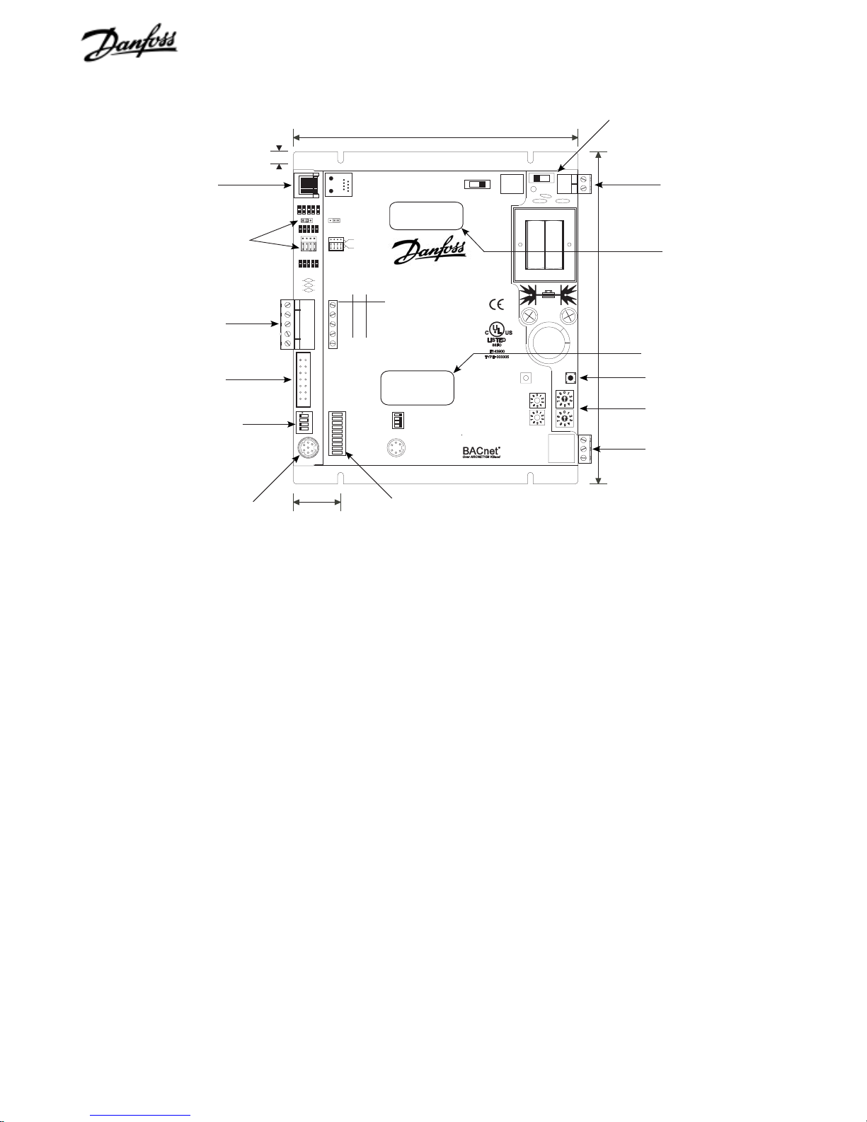
Figure 1. BACLink Portal
Power switch. Two position on/off power switch.
Portal address label. Identifies factory-set or default portal
addresses.
Port connectors label. Identifies factory-settings for
communication ports 1 and 2. Default setting for port 1 is
unassigned. Default setting for port 2 is EIA-485.
24 VAC connector. Input power for BACLink module.
Format button. Normally not used with BACnet. Contact the
Danfoss Graham service department for information on its use to
clear factory-set programming.
Address rotary switches. Rotary switches used to set BACLink
portal network addresses. Set addresses 01-99 with DIP switch 5
in the +0 position. Set addresses 100-199 with DIP switch 5 in the
+100 position.
5
Depth: 1
/8"
LED indicators. Status indicator lights for functions as labeled.
Access port. Utility port for factory programming, set up, and to
assign the IP address. The access port cannot be used as a
communication point or to download memory to the BACLink.
DIP switches. Two position switches used to enable selection of
IP address, module address, and network type. Sw1 and Sw2
are disabled in VLT communication applications.
Keypad/Display port. Access port for optional keypad.
Port 2. Preferred port for EIA-485 connection to the VLT drives.
The terminal is jumper selectable for 2-wire/4-wire EIA-485 or
EIA-232. Default setting is EIA-485 (2-wire).
Port 2 configuration jumpers. Jumper placement determines
the configuration for EIA-485 (2-wire), EIA-485 (4-wire), or
EIA-232 communication for Port 2. Default is EIA-485 2-wire.
Port 1. Preferred port for ARCnet connection. Selectable for
ARCnet or 2-wire EIA-485. Set DIP switch 4 (Port 1) to Other to
enable linking drives with EIA-485 wiring. Set DIP switch 4 (Port
1) to ARC156 for use as ARCnet connector. (See DIP switches.)
6
VLT is a registered Danfoss trademark
Ethernet port. Ethernet network connector supports 10baseT
network communication with BACLink.
Page 6
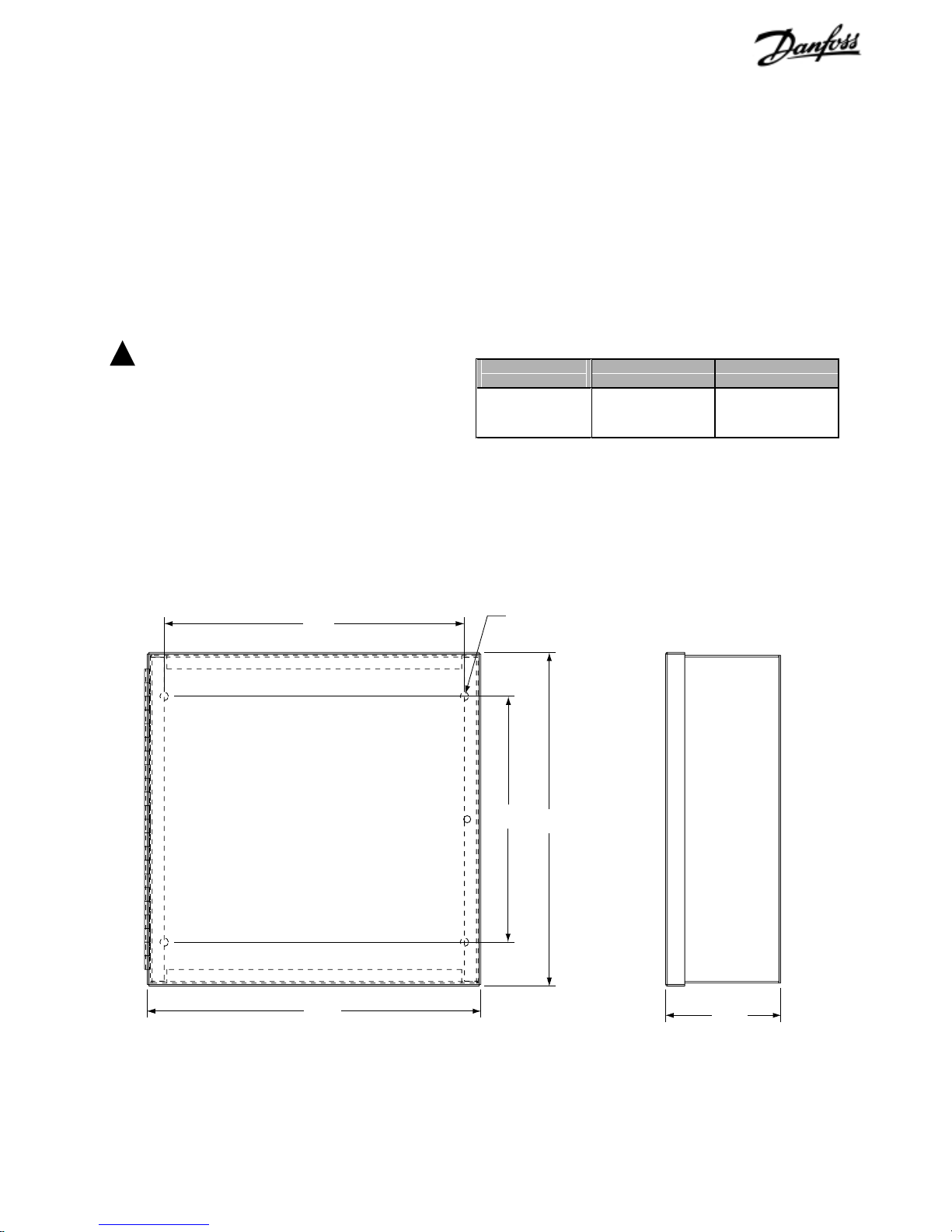
Mounting requirements
Wiring and terminal tightening specifications
Mount the BACLink enclosure as required using the predrilled
mounting holes (see Figure 2). The unit weighs approximately
15.3 pounds (7 kg).
For BACLink portals ordered without an enclosure, mount the unit
in an enclosed panel using the mounting holes provided on the
BACLink portal backplate (refer back to Figure 1). Leave about 2
inches (5 centimeters) on each side for wiring access. In addition,
the BACLink portal requires 24 VAC input power.
WARNING
!
BACLink portal is a Class 2 device (less
than 30VAC, 100VA maximum). Take
appropriate isolation measures when
mounting BACLink portal in control panels
where non-Class 2 devices (for example,
120V AC) or wiring are present.
Terminal tightening and wire specifications for the VLT2800 and
VLT 6000 are defined in Table I.
Total wiring length to connect up to 10 VLT 6000 and VLT 2800
drives from the BACLink portal should not exceed 3,000 feet
(900m) at 9600 baud rate.
Table I. Control Wiring and Torque
Specifications
Torque
Specification
4.5 in-lbs (0.5 Nm) 18 – 24 AWG
Control Wiring 24 VAC Input Wiring
2
(0.75mm
shielded twisted pair
2
– 0.2mm2)
22 AWG (0.3mm
)
11.00
[279.4]
12.22
[310.4]
0.31
∅
[7.9]
4 PLCS.
9.00
[228.6]
12.22
[310.4]
4.21
[107.0]
Figure 2. BACLink Enclosure Mounting Dimensions
NOTE: Dimensions in inches [mm].
VLT is a registered Danfoss trademark
7
Page 7
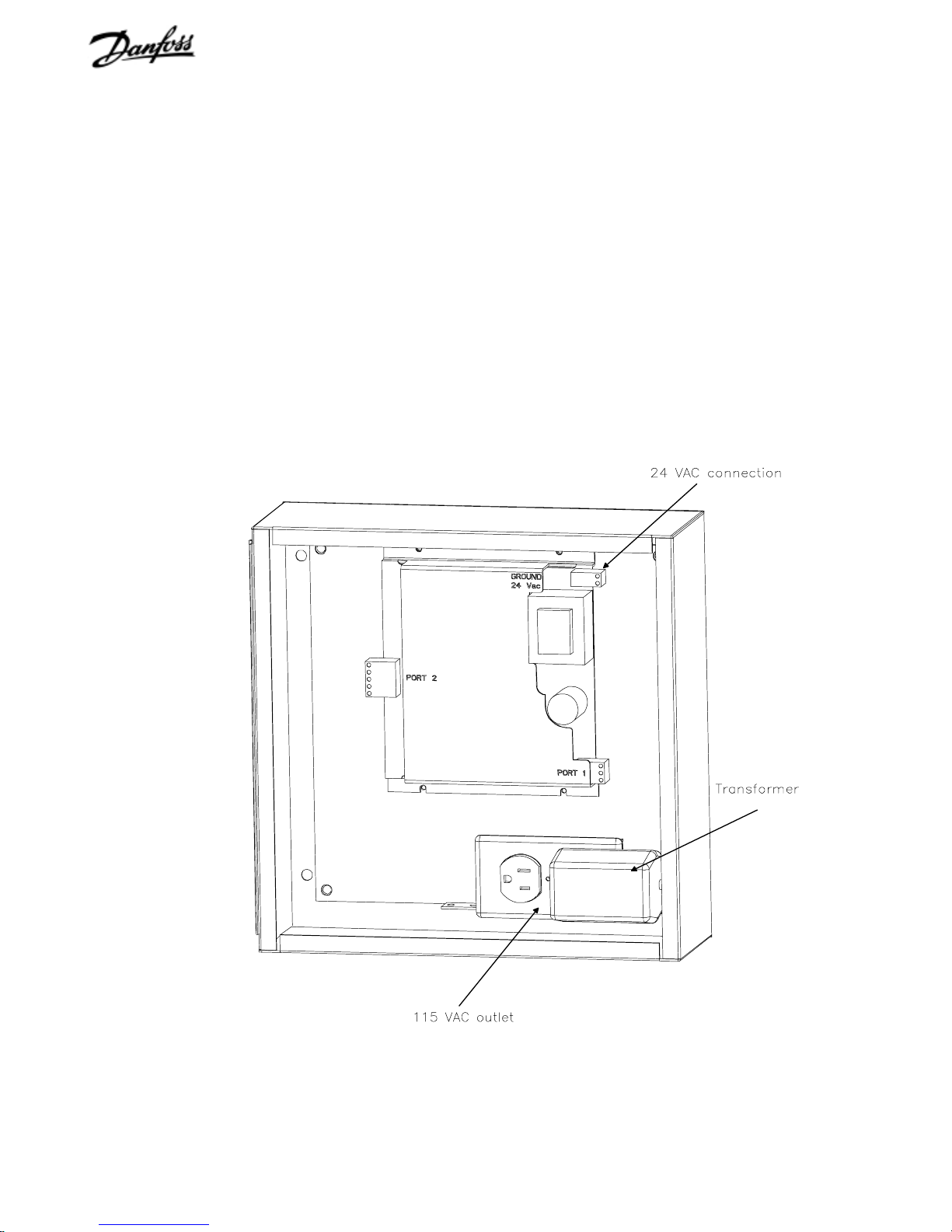
Electrical wiring
1. Power must be supplied to the 115 VAC outlet from an
external source (see Figure 3).
2. Plug transformer into 115 VAC outlet.
3. Connect transformer cable to 24 VAC connector on
BACLink board.
Figure 3. BACLink Enclosure Electrical Components
8
VLT is a registered Danfoss trademark
Page 8

VLT 6000 network connection
VLT 6000 network wiring
VLT 6000 termination switch settings
DIP switches 2 and 3 on the main control board of the VLT6000
(see Figure 4) are used to configure the drive for BACnet serial
bus termination. The switch position shown is the factory setting.
See Table II for setting information. The DIP switch are located
directly above terminals 61, 68 and 69 on the board.
Figure 4. VLT 6000 DIP Switch
1. Connect signal wires to drive terminal 68 (P+) and terminal
69 (N-) on main control board of drive (see figure 5).
2. If shielded cabling is used, connect one end of shield to
terminal 61. This terminal is connected to ground via an
internal RC link.
For additional wiring guidelines, see the procedures for specific
network-type connections in this manual.
NOTE
It is highly recommended to use shielded,
twisted-pair wires to reduce electrical noise
on drive communications. Ensure that
drive is grounded properly according to
instructions in the drive manual.
61
68
69
COM
EIA-485
EIA-485
Figure 5. VLT 6000 Network Wiring
Table II. VLT 6000 DIP Switch Settings
SWITCH
SETTING
Switch 1 Reserved/No function
Switches 2 & 3 Used for terminating an EIA-485 interface. W hen
the drive is the first, last, or only device on a
network, switches 2 and 3 must be ON.
When the drive is in any other location on the
network, switches 2 and 3 must be OFF.
Switch 4 Not applicable with BACnet.
N(-)
P(+)
VLT is a registered Danfoss trademark
9
Page 9
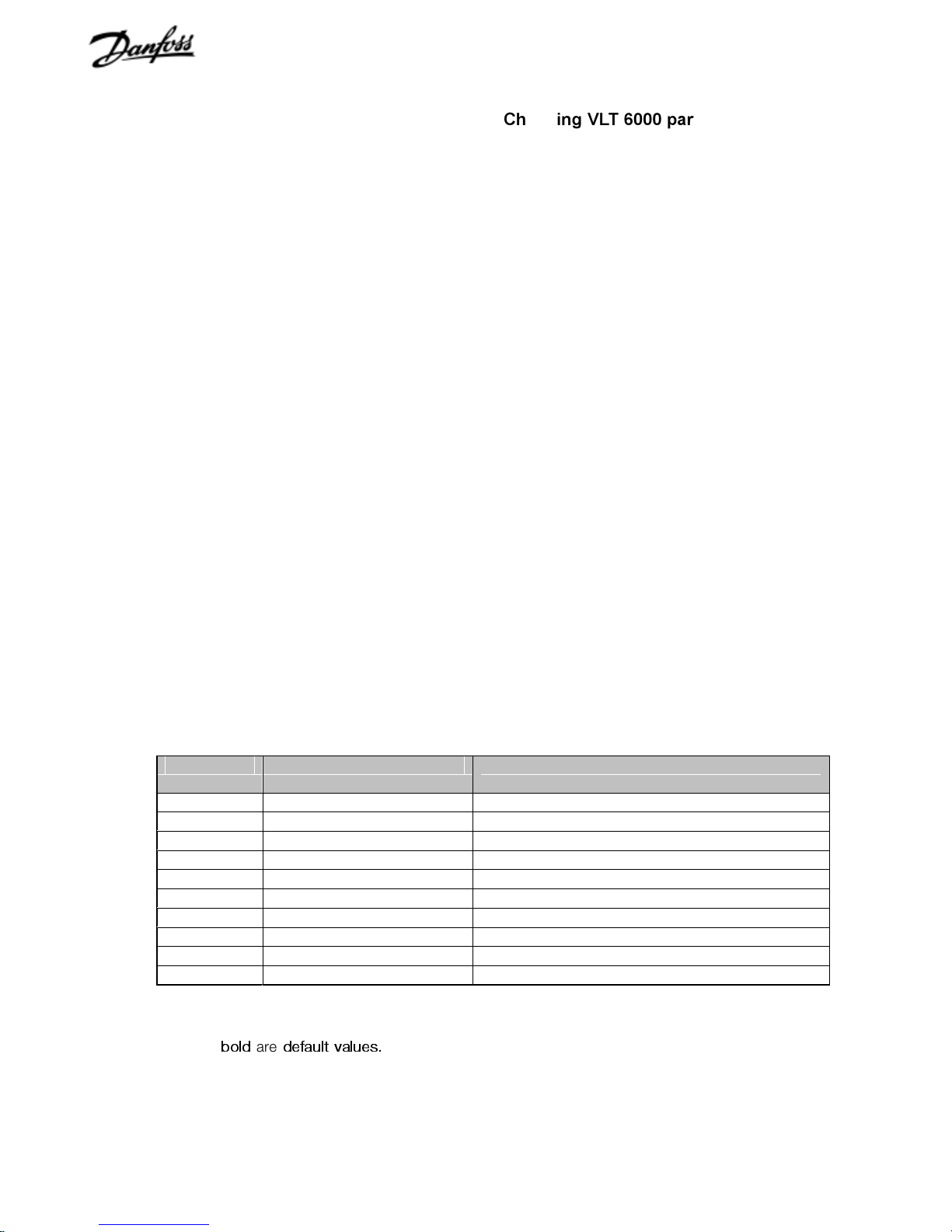
VLT 6000 BACnet start up
Changing VLT 6000 parameter data
The BACLink portal will have factory default settings ready for
operation without user adjustment. Parameters 500, 501 and 502
must be set as shown in Table III. Other settings may be
changed to meet application requirements. Refer to the VLT 6000
Installation, Operation and Maintenance Manual for details on
programming the drive.
The appendix in this manual lists point maps for BACnet.
Use the VLT 6000 keypad to access the Extended Menu key and
the 500 Group (serial communication) parameters. Enter or
change parameter data or settings in accordance with the
following procedure.
1. Press [Extend Menu] key.
2. Use t and u keys to find parameter group to edit.
3. Use [+] and [-] keys to find parameter you chose to edit.
4. Press [Change Data] key.
5. Use [+] and [-] keys to select correct parameter setting.
6. Press [Cancel] key to disregard change, or press [OK] key
to accept change and enter new setting.
7. Press [Display Mode] key to return to normal drive display.
Table III. VLT 6000 Serial Communication Startup Parameter Settings
Parameter Name Setting
500 Protocol METASYS N2
501 Address 01
502 Baud rate 9600 BAUD (fixed at 9600 for N2 protocol)
503 Coasting LOGIC OR
504 DC brake LOGIC OR
505 Start LOGIC OR
506 Reversing DIGITAL INPUT
507 Select setup LOGIC OR
508 Select speed LOGIC OR
560 Override release time OFF
The values in
bold
are
default values.
10
VLT is a registered Danfoss trademark
Page 10

VLT 2800 network connection
VLT 2800 BACnet start up
1. Connect signal wires to drive terminal 68 (P+) and terminal
69 (N-) on main control board of drive (see Figure 6).
2. If shielded cabling is used, observe standard shielding
practice by grounding shielded wiring at only one point in
system.
For additional wiring guidelines, see the procedures for specific
network-type connections in this manual.
NOTE
It is highly recommended to use shielded,
twisted-pair wires to reduce electrical noise
on drive communications. Ensure that
drive is grounded properly according to
instructions in the drive manual.
67
68
69
70
The BACLink portal will have factory default settings ready for
operation without user adjustment.
Parameters 500, 501 and 561 must be set as shown in Table
IV. Other settings may be changed to meet application
requirements. The settings shown will serve as a good starting
reference. Refer to the VLT2800 Operating Instructions for
details on changing parameters and programming the drive.
The appendix in this manual lists point maps for BACnet.
Changing VLT 2800 parameter data
Use the VLT 2800 keypad to access the Menu Mode and the 500
Group (serial communication) parameters. Enter or change
parameter data or settings in accordance with the following
procedure.
1. Press [Quick Menu] and [+] key at same time to enter menu
mode.
2. Use [+] and [-] keys to find parameter you chose to edit.
3. Press [Change Data] key.
N(-)
EIA-485
P(+)
EIA-485
Figure 6. VLT 2800 Network Connection
Table IV. VLT 2800 Serial Communication Startup Parameter Settings
Parameter Name Setting
500 Address
501 Baud rate
502 Coasting
503 Quick stop
504 DC brake
505 Start
506 Reversing
507 Select setup
508 Select speed
560 N2 Override release time
561 Protocol
The values in
bold
are
default values.
4. Use [+] and [-] keys to select correct parameter setting.
5. Press [Change Data] key to accept change and enter new
setting or press [Quick Menu] key to disregard change.
6. Press [Quick Menu] key to return to display mode.
001
9600 BAUD (fixed at 9600 for N2 prot oc ol)
LOGIC OR
LOGIC OR
LOGIC OR
LOGIC OR
LOGIC OR
LOGIC OR
LOGIC OR
OFF
METASYS N2
VLT is a registered Danfoss trademark
11
Page 11

Ethernet network connection
Procedure
The Ethernet network connects directly to the BACLink Ethernet
portal (refer back to Figure 1). The connection is a 10baseT port.
Both Ethernet and Ethernet IP (BACnet IP) connect through this
connector.
To establish Ethernet communication with the BACLink portal and
VLT drives, the following must be completed:
1. Wiring
2. Setting IP address of portal
3. For port 2 connection, setting port 2 configuration jumpers
Ethernet
Standard default
VLTÆ BACLink
1. Wiring
Wire Connections. Each BACLink portal can support up to 10
drives (see Figure 7). Any mix of VLT 2800 or VLT6000 drives is
supported.
The preferred portal-to-drive wiring is EIA-485 from port 2.
Connect portal Net+ to drive terminal 68 (+) and Net- to 69 (-).
Additional drives are connected pos-to-pos and neg-to-neg in
daisy chain fashion.
If required, port 1 can be factory-configured to connect the drives
through EIA-485.
ô
VLTÆ BACLink
ô
Optional factory setting
NOTE: EIA-485 (2-wire)
Net+ and Net- from Port 2
to drive input terminals
68 (+) and 69 (-)
EIA-485
EIA-485
12
VLT is a registered Danfoss trademark
Figure 7. Ethernet Network Connection
Page 12

NOTE
Steps 2 and 3 in the following connection
procedure may have already been factory-set
based upon customer ordering information.
Default IP address is 192.168.168.xxx.
Default subnet mask is 255.255.255.0.
Default gateway address is 0.0.0.0.
2. Set IP address of portal
C. Set BACLink portal address DIP switch. The BACLink
portal DIP switch 5 (refer back to Figure 8) must correspond to the
final portion of the IP address setting. Set the switch to +0 for
addresses 0to 99 or to +100 for addresses 100 to199.
3. Set configuration jumpers on portal
See the port connector label attached to the BACLink portal for the
factory-configured port assignments (refer back to Figure 1).
A. Set IP address to default or assigned. The BACLink portal
has either an internal default Internet Protocol (IP) address or a
factory-set IP address assigned from customer input. See the label
attached to the portal for the IP address in either case (refer back
to Figure 1). An IP address must always be present for Ethernet
IP network communication. Set the IP address DIP switch (switch
3 in Figure 8) on the BACLink portal as either default or assigned.
(Switches 1 and 2 are disabled.)
Switch 1
Switch 2
IP Address
Port 1
Portal Address
1
Off/ On
Off/ On
2
3
Default/Assigned
ARC156/ Other
4
5
+0/+100
Figure 8. BACLink DIP Switches
B. Set BACLink default address. The default IP address is
192.168.168.xxx. The xxx indicates the final portion of the IP
address which is set using the rotary switches on the BACLink
portal. The final portion of the address identifies the BACLink portal
with a unique address on the BACnet network. For example,
using the default address, Figure 9 shows the BACLink portal
address configured as 192.168.168.3. Set the user-assigned final
portion of the portal network address using the rotary switches.
Set port 2 configuration jumpers for communication type.
When using port 2 on the BACLink portal for communication with
the drives, set the port 2 configuration jumpers for EIA-485
(2-wire). Figure 10 illustrates the appropriate setting. EIA-485
(2-wire) is the factory default setting.
485-2w
485-4w
EIA-232
EIA-485
Figure 10. Port 2 Configuration Jumpers
When using port 1. Port 1 must be programmed for operation at
the factory based upon customer ordering data. When using
port1 on the BACLink portal for communication with the drives, set
the port 1 DIP switch (refer back to Figure 8) for ARC156 when
using an ARCnet interface to the drives or Other for EIA-485 or
additional options.
10's digit
0
9
8
7
6
1
2
3
4
5
1's digit
9
8
7
6
Figure 9. Rotary Address Switches
For Ethernet connection without IP, an IP address is not used.
Use the rotary address switches to assign the media access
control (MAC) address.
0
1
2
3
4
5
VLT is a registered Danfoss trademark
13
Page 13

ARCnet network connection
Procedure
EIA-485
NOTE: EIA-485 Net+
and Net- from Port 2
to drive input terminals
68 (+) and 69 (-)
ARCnet
VLT® BACLink
™
ARCnet
1. Switch BACLink portal power off.
2. Wire ARCnet network input cable to BACLink port1 (see
Figure 11).
3. Set port 1 DIP switch to ARC156 (see Figure 12).
4. Plug EIA-485/232 configuration jumper to EIA-485 position
as shown in Figure 13.
5. Set portal device instance number using rotary address
switches (see Figure 14).
6. Set BACLink portal address DIP switch. BACLink portal
DIP switch 5 (refer back to Figure 1) must correspond to
device instance number setting. Set switch to +0 for
addresses 0to 99 or to +100 for addresses 100 to199.
7. Wire to drives from BACLink port 2 from Net (+) to drive
terminal 68 and Net (-) to drive terminal 69.
Switch 1
Switch 2
IP Address
Port 1
Portal Address
1
Off/ On
Off/ On
2
3
Default/Assigned
ARC156/ Other
4
5
+0/+100
NOTE: Terminate shield at only
one portal of a multiportal
network.
Shield
Port 1
Net -
Net +
ARC156 Network
Figure 11. ARCnet Network Connection
Figure 12. BACLink DIP Switches
EIA-232
EIA-485
Figure 13. Port 2 Configuration Jumper Settings
10's digit
0
9
8
7
6
1
2
3
4
5
1's digit
9
8
7
6
0
1
2
3
4
5
Figure 14. Rotary Address Switches
14
VLT is a registered Danfoss trademark
Page 14

EIA-485 network connection
Procedure
EIA-485
EIA-485
VLT® BACLink
1. Switch BACLink portal power off.
2. Wire EIA-485 network input cable to BACLink port1 (see
Figure 15).
™
3. Set port 1 DIP switch to Other (see Figure 16).
4. Plug EIA-485/232 configuration jumper to EIA-485 position
EIA-485
as shown in Figure 17.
5. Plug EIA-485 configuration jumper to (2-wire) position as
shown in Figure 17.
7. Wire to drives from BACLink port 2 from Net (+) to drive
terminal 68 and Net (-) to drive terminal 69.
Switch 1
Switch 2
IP Address
Port 1
Portal Address
1
Off/ On
Off/ On
2
3
Default/Ass igned
ARC156/ Other
4
5
+0/+100
NOTE: EIA-485 (2-wire)
from Port 2 to drive input
terminals 68 (+) and 69 (-)
Figure 15. EIA-485 (2-wire) Network Connection
Figure 16. BACLink DIP Switches
485-2w
485-4w
EIA-232
EIA-485
Figure 17. Port 2 Configuration Jumper Settings
VLT is a registered Danfoss trademark
15
Page 15

EIA-232 network connection
Procedure
EIA-232
Tx (+) pin1
Rx (-) pin 2
GND pin 5
VLT® BACLink
1. Switch BACLink portal power off.
2. Wire EIA-232 network input cable to BACLink port2 (see
Figure 18). Tx (+) pin 1, Rx (-) pin 2, GND pin 5.
™
3. Set port 1 DIP switch to Other (see Figure 19).
4. Plug EIA-485/232 configuration jumper to EIA-232 position
EIA-485
as shown in Figure 20.
5. Wire to drives from BACLink port 2 from Net (+) to drive
terminal 68 and Net (-) to drive terminal 69.
Switch 1
Switch 2
IP Address
Port 1
Portal Address
1
Off/ On
Off/ On
2
3
Default/Ass igned
ARC156/ Other
4
5
+0/+100
Figure 18. EIA-232 Network Connection
Figure 19. BACLink DIP Switches
EIA-232
EIA-485
Figure 20. Configuration Jumper Settings
16
VLT is a registered Danfoss trademark
Page 16

Power up
1. Turn BACLink power switch to OFF. This prevents
BACLink from power up before proper voltage is verified.
3. For VLT 6000, termination DIP switches 2 and 3 should be
in the ON position. Termination DIP switches are located on
VLT 6000 power board directly above drive terminals
where connections to terminals 68 and 69 are made.
2. Ensure that power is applied to the drives.
3. Plug connector from transformer to BACLink 24 VAC
power terminal.
4. Ensure that 24 VAC is present at BACLink power input
terminals.
5. Turn BACLink power switch to ON. Power, Run and Error
LEDs turn on. Run and Error LEDs then begin blinking.
Error LED turns off.
Troubleshooting drive communication
For use in the event of trouble communicating with the drives. Test
conditions for BACLink portal communications:
1. Test only one drive connected to portal at a time.
2. Portal power OFF.
Table V. Troubleshooting Drive Communication
SYMPTOM CAUSE SOLUTION
Transmit LED ON steady
and receive LED OFF.
Transmit LED blinks slowly 3
times, then pauses and
repeats 3 blinks.
Reversed polarity to drive or short in
EIA-485 cable.
•
Drive not ON.
•
Drive not set for N2 protocol in
parameter 500.
•
Drive serial bus address not
correct in parameter 501.
•
Network cable not connected.
•
For VLT 6000: termination
switches on drive in wrong
position.
4. Drive power ON.
5. Apply power to portal and wait 20-25 seconds. (See
TableV for test results.)
Troubleshooting Ethernet communication
With the BACLink portal connected to BACnet network through the
Ethernet connector, apply power to BACLink portal and switch
portal ON. See Table VI for test results.
Loss of signal recovery time
When serial communication is lost to the drive, recovery time to
reestablish communication with the network can take up to
5minutes.
Reverse wires to drive terminals 68
(+) and 69 (-) or remove short.
•
Apply power to drive.
•
Set parameter 500 for N2
protocol.
•
Set drive address in
param et er 501 .
•
Connect network cable to
unit.
•
Set termination switches 2
and 3 to ON position.
Table VI. Troubleshooting Ethernet Communication
SYMPTOM CAUSE SOLUTION
Link LED is OFF.
Lan LED is OFF.
• Networ k speed set to
• BACLink board not
•
100kbps.
connected to network
Portal address not
set for network or not
recognized.
• Set network speed for 10kbps.
•
Connect board to network.
•
Ping portal to test communications. To
ping portal, go to a DOS prompt on any
network computer. Type “ping” and the
portal address (displayed on the IP
address label on the unit) and press
enter. If communicating, you will get a
reply. If not communicating, you will get
no response indication.
VLT is a registered Danfoss trademark
17
Page 17

BACnet POINT MAPPING TABLES
Binary Inputs to Drive
Appendix
for BACLink PORTAL
BACnet
REFERENCE NUMBER
coast_# Motor will coast freely to a stop.
Drive will not run in any mode
when coast is active.
start_# Provides a start command when
active. Motor will ramp to stop
when stop is active.
reset_# Allows resetting drive after a fault
that does not require cycling
power. Reset occurs at transition
from OFF to ON.
jog_# Used to start and run drive at a
frequency set in parameter 209.
vlt2800_relay_# Enables/disables high voltage
Form C relay when parameter 323
is set to
(for VLT 2800 only).
vlt6000_relay_2_# Enables/disables low voltage
Form A relay when parameter 323
is set to
[29] (for VLT 6000 only).
vlt6000_reverse_# Changes motor direction of
rotation when parameter 506 is set
to a value other than
(for VLT 6000 only).
relay_1_and_reverse_# For VLT 2800, changes motor
direction of rotation.
For VLT 6000, enables/disables
high voltage Form C relay when
parameter 323 is set to
Word Bit 11/12
The values in
bold
are
default values.
DESCRIPTION
Control Word Bit 11
Control Word Bit 11/12
[26]
Digital Input
Control
[29].
RANGE
0=Coast stop
coast
0=Stop
0=Off
1=On
0=Off
1=On
0=Off
1=On
0=Off
1=On
0=Off
1=On
0=Off
1=On
1=No
1=Start
NOTE
Binary input point 9 commands two different
functions. For VLT 2800, it commands
reverse function to change direction of
motor rotation. For VLT 6000, it can
command the state of Form C relay .
18
VLT is a registered Danfoss trademark
Page 18

Analog Inputs to Drive
BACnet
REFERENCE NAME
bus_ref_# Drive speed command
bus_feedback_# Drive feedback value
bus_feedback_2_# Second drive feedbac k
NOTE: # symbol represents drive ID number.
DESCRIPTION
(open loop) or setpoint
(closed loop) via the
serial bus.
via the serial bus.
value via the serial bus
available in the
VLT 6000 only.
RANGE
VLT 6000
PARA No.
VLT 2800
PARA No.
0% to 100% N/A N/A
0% to 100% 535 535
0% to 100%
536 VLT 6000
only
Bus reference. When the drive is set for open loop operation in
parameter 100, the bus reference is the speed command to the
drive. In closed loop operation, bus reference is the drives
Bus feedback. This is the feedback signal provided to the drive
via the BACnet bus. The VLT 6000 can regulate two feedback
signals provided to the drive.
setpoint.
Range. Percentage of range between minimum reference
(parameter 204) and maximum reference (parameter 205).
Drive Settings
BACnet
REFERENCE NAME
vlt6000_reset_counter_# Resets kWh counter
vlt6000_active_setup_# Selects active setup
vlt2800_prop_gain_# P ID proportional gain
vlt2800_int_time_# PID integration time
vlt2800_fb_filter_time_# Feedback filter time
warn_feedback_low_# Warning low feedback
warn_feedback_high_# Warning high feedback
setpoint_1_# Set point 1
setpoint_2_# Set point 2
vlt6000_prop_gain_#
vlt6000_int_time_# PID integration time
vlt6000_fb_filter_time_# Feedback filter time
NOTE: # symbol represents drive ID number.
The values in
bold
are
default values.
DESCRIPTION
(for VLT 6000 only)
(for VLT 6000 only)
(for VLT 2800 only)
(for VLT 2800 only)
(for VLT 2800 only)
(for VLT 6000 only)
(for VLT 6000 only)
(for VLT 6000 only)
(for VLT 6000 only)
PID proportional gain
(for VLT 6000 only)
(for VLT 6000 only)
(for VLT 6000 only)
0=no rest
1=reset
1 to 4 002 VLT 6000
0.00 to10.00 VLT 2800
0.01 to
9999.00 sec.
0.01 to10.00
sec.
-999,999.999
to F B high
FB low to
999,999.999
Min. FB to
max. FB
Min. FB to
max. FB
0.00 to10.00 423 VLT 6000
0.01 to
9999.00 sec.
0.01 to10.00
sec.
RANGE
VLT 6000
PARA NO.
618 VLT 6000
only
VLT 2800
only
VLT 2800
only
227 VLT 6000
228 VLT 6000
418 VLT 6000
419 VLT 6000
424 VLT 6000
427 VLT 6000
VLT 2800
PARA NO.
only
only
440
441
444
only
only
only
only
only
only
only
Appendix
VLT is a registered Danfoss trademark
19
Page 19

Analog Outputs from Drive
BACNet
Reference Name
reference_# % Reference in % between min
feedback_# Par.
freq_# Hz Drive output frequency. 512 518
motor_curr_# Amp Current being supplied to motor. 514 520
power_# kW Power being supplied to motor. 515 522
motor_volt_# VAC Voltage being supplied to motor. 517 524
dc_bus_volt_# VDC DC bus voltage of drive. 518 525
therm_motor_load_# % Calculated thermal load on
therm_inverter_load_# % Calculated thermal load on
term_53_analog_# VDC Voltage value on analog input
term_54_analog_# VDC Voltage value on analog input
term_60_analog_# mA Current value on analog input
heatsink_temperature_#
operating_hours_# Hour Number of hours power applied
run_hours_# Hour Number of hours drive applied
kwh_counter_# kWh Output power of drive in hours. 602 602
UNIT
415
C
°
DESCRIPTION
and max reference. Speed
reference in open loop. Setpoint
reference in closed loop.
Feedback using the unit of
measure selected in parameter
415.
motor. Trip point is 100%.
drive. Trip point is 100%.
Terminal 53.
Terminal 54 (for VLT 6000 only).
Terminal 60.
Drive heatsink temperature. 528 537
to drive.
power to motor.
VLT 6000
PARA NO.
509 515
511 517
519 526
520 527
522 529
523 VLT 6000
524 531
600 600
601 601
VLT 2800
PARA NO.
only
NOTE: # symbol represents drive ID number.
20
VLT is a registered Danfoss trademark
Appendix
Page 20

Binary Outputs from Drive (status)
BACnet
REFERENCE NAME
current_status_#
voltage_status_#
motor_run_status_#
frequency_status_#
control_status_# 0=Local
reference_status_#
warning_status_#
trip_status_#
coast_status_# 0=Not Enabled
heatsink_temp_#
vlt2800_term_33_#
frequency_low_#
frequency_high_#
current_low_#
current_high_#
feedback_low_#
feedback_high_#
live_zero_error_#
phase_loss_#
drive_therm_overload_#
motor_therm_overload_#
current_limit_#
external_fault_#
(safety interlock)
over_temp_#
earth_fault_#
trip_lock_#
standby_#
jogging_#
hand_mode_#
off_#
local_ref_#
running_at_ref_#
sleep_mode_#
NOTE: # symbol represents drive ID number.
The values in
bold
are
default values.
VLT 6000
SELECTION
0=OK
1=Limit 527 534
0=OK
1=Limit 527 534
0=Not Running 1=Running
0=Out of Range 1=In
Range
1=Remote
0=Not on Ref. 1=On Ref.
0=OK 1= Warning
0=OK
1=Tripped 527 534
0=OK
1=Warning
(for VLT 2800 only)
0=Off 1=On
(for VLT 2800 only)
0=OK 1=Warning
0=OK 1=Warning
0=OK 1=Warning
0=OK
1=Warning 531 540
0=OK
1=Warning 531 540
0=OK 1=Warning
0=OK 1=Warning
0=OK 1=Warning
0=OK
1=Warning 531 540
0=OK
1=Warning 531 540
0=OK 1=Warning
0=OK 1=Alarm
(for VLT 6000 only)
0=OK 1=Alarm
0=OK 1=Alarm
(for VLT 6000 only)
0=OK
1=Trip Lock 529 538
0=False
(for VLT 6000 only)
0=False
(for VLT 6000 only)
0=Auto
(for VLT 6000 only)
0=False 1=True
(for VLT 6000 only)
0=False
(for VLT 6000 only)
0=False 1=True
(for VLT 6000 only)
0=False 1=True
(for VLT 6000 only)
1=True
1=True
1=Hand
1=True
527 534
1=Enabled
PARA NO.
527 534
527 534
527 534
527 534
527 534
VLT 2800
only
VLT 2800
only
531 540
533 540
531 540
531 540
531 540
531 540
531 540
529 VLT 6000
529 538
529 VLT 6000
532 VLT 6000
532 VLT 6000
532 VLT 6000
532 VLT 6000
532 VLT 6000
532 VLT 6000
532 VLT 6000
VLT 2800
PARA NO.
540
528
only
only
only
only
only
only
only
only
only
Appendix
VLT is a registered Danfoss trademark
21
Page 21

Binary Outputs from Drive (continued)
BACnet
REFERENCE NAME
reverse_#
vlt6000_term_33_# 0=Off 1=On
terminal_32_#
terminal_29_#
terminal_27_# 0=Off 1=On
terminal_19_#
terminal_18_# 0=Off 1=On
terminal_17_#
terminal_16_#
NOTE: # symbol represents drive ID number.
The values in
bold
are
default values.
SELECTION
0=False 1=True
(for VLT 6000 only)
(for VLT 6000 only)
0=Off 1=On
(for VLT 6000 only)
0=Off 1=On
(for VLT 6000 only)
(for VLT 6000 only)
0=Off 1=On
(for VLT 6000 only)
(for VLT 6000 only)
0=Off 1=On
(for VLT 6000 only)
0=Off
1=On
(for VLT 6000 only)
VLT 6000
PARA NO.
530 VLT 6000
521 VLT 6000
521 VLT 6000
521 VLT 6000
521 VLT 6000
521 VLT 6000
521 VLT 6000
521 VLT 6000
521 VLT 6000
VLT 2800
PARA NO.
only
only
only
only
only
only
only
only
only
22
VLT is a registered Danfoss trademark
Appendix
Page 22

Danfoss Graham
Division of Danfoss Inc.
8800 West Bradley Road
P.O. Box 245041
Milwaukee, Wisconsin 53224-9541
Phone: (414) 355-8800 Fax: (414) 355-6117
Toll free: (800) 621-8806
E-mail: graham@grahamdrives.com
http://www.namc.danfoss.com
 Loading...