

Technical Information
Series 45
Axial Piston Open Circuit Pumps
www.danfoss.com

Technical Information
Series 45 Pumps
Revision history Table of revisions
Date Changed Rev
January 2022 Clarified importance of relief valve for system protection; added mounting flange technical
data to frame F
April 2021 Added K2 040C displacement performance graphs 1104
June 2020 Changed document number from 'BC00000019' and '520L0519' to 'BC152886483703' 1103
October 2019 Added K2 040C displacement technical data 1001
July 2019 Removed excess content 0903
June 2019 Removed M1 ports from K2 schematics and other minor changes 0902
March 2018 Minor updates 0901
September 2017 Corrected performance curves for K2 Pumps 0812
August 2017 Corrected typo 0811
April 2017 Update the TOC 0810
March 2017 add K2 Frame 0809
July 2016 Fan Drive Control configuration-corrected G and H model code tables 0808
July 2016 Fan Drive Control configuration-included G and H model code tables 0807
June 2016 Various edits - Fan Drive Control 0806
April 2016 Various edits - Fan Drive Control 0805
March 2016 Add Fan Drive Control 0804
1201
March 2015 Add E Frame ETL control and Angle Sensor HC
October 2014 Add ETL control and Angle Sensor HB
July 2014 Danfoss layout HA
2 | © Danfoss | January 2022 BC152886483703en-001201

Technical Information
Series 45 Pumps
Contents
General Information
Overview..............................................................................................................................................................................................8
Design...................................................................................................................................................................................................8
Benefits.................................................................................................................................................................................................8
Typical applications.........................................................................................................................................................................9
The Series 45 product family........................................................................................................................................................9
Load sensing open circuit system............................................................................................................................................11
Servo Control Orifice.....................................................................................................................................................................12
Servo Control Orifice Principle.............................................................................................................................................12
Servo Control Orifice Performance.................................................................................................................................... 13
Pacing Factor..............................................................................................................................................................................14
Hydraulic Controls......................................................................................................................................................................... 14
Pressure compensated controls..........................................................................................................................................14
Operation............................................................................................................................................................................... 14
Pressure compensated system characteristics.........................................................................................................15
Typical applications for pressure compensated systems.....................................................................................15
Remote pressure compensated controls.........................................................................................................................15
Remote pressure compensated system characteristics........................................................................................16
Typical applications for remote pressure compensated systems..................................................................... 17
Load sensing controls.............................................................................................................................................................17
LS control with bleed orifice............................................................................................................................................17
Integral PC function............................................................................................................................................................18
Load sensing system characteristics............................................................................................................................ 18
Electric Controls..............................................................................................................................................................................18
Electric Proportional Controls (EPC)...................................................................................................................................18
PLUS+1® Compliance......................................................................................................................................................... 18
Electric Proportional Control Principle........................................................................................................................18
Electric Proportional Control Response/Recovery..................................................................................................19
Electric Proportional Control Characteristic – Normally Closed.........................................................................20
Electric Proportional Control Characteristic – Normally Open...........................................................................21
Electric On-Off Controls..........................................................................................................................................................23
PLUS+1 Compliance...........................................................................................................................................................23
Electric On-Off Control Principle....................................................................................................................................23
Electric On-Off Control Response/Recovery..............................................................................................................24
Electric On-Off Control Performance vs. Ambient Temperature Characteristic...........................................24
Electric On-Off Control Characteristic – Normally Closed.................................................................................... 25
Electric On/Off Control Characteristic – Normally Open.......................................................................................26
Electric dump valve PC/LS controls....................................................................................................................................27
Electronic Torque Limiting Controls (ETL).......................................................................................................................27
PLUS+1 Compliance...........................................................................................................................................................27
Electric Torque Limiting Control Principle................................................................................................................. 28
Electronic Torque Limiting Control Characteristic..................................................................................................29
Fan Drive Control (FDC)..........................................................................................................................................................29
PLUS+1 Compliance...........................................................................................................................................................29
Fan Drive Control Principle .............................................................................................................................................31
Fan Drive Control System Characteristics.................................................................................................................. 31
Unintended Applications for Fan Drive Control Systems.....................................................................................32
Fan Drive Control characteristic - Normally Closed ...............................................................................................32
Solenoid data – Normally closed...................................................................................................................................33
Fan Drive Control configuration....................................................................................................................................35
NC Fan Drive Control 3D Views......................................................................................................................................35
Angle Sensor....................................................................................................................................................................................35
PLUS+1 Compliance................................................................................................................................................................ 35
Angle Sensor Principle............................................................................................................................................................36
Angle Sensor Characteristics................................................................................................................................................36
J & F-Frame (45-90cc) Angle Sensor Identification Convention:........................................................................37
E-Frame (100-147cc) Angle Sensor Identification Convention:..........................................................................37
Angle sensor electrical specifications............................................................................................................................... 40
Angle Sensor Calibration....................................................................................................................................................... 40
©
Danfoss | January 2022 BC152886483703en-001201 | 3

Technical Information
Series 45 Pumps
Contents
Frame K2
Angle Sensor Functionality...................................................................................................................................................40
Charge Pump Circuits...................................................................................................................................................................40
Example Circuit #1....................................................................................................................................................................40
Example Circuit #2....................................................................................................................................................................41
Operating parameters..................................................................................................................................................................42
Fluids.............................................................................................................................................................................................42
Viscosity........................................................................................................................................................................................42
Temperature...............................................................................................................................................................................42
Inlet pressure..............................................................................................................................................................................43
Case pressure............................................................................................................................................................................. 43
Pressure ratings.........................................................................................................................................................................44
Speed ratings............................................................................................................................................................................. 44
Duty cycle and pump life.......................................................................................................................................................44
Speed, flow, and inlet pressure............................................................................................................................................45
Design parameters........................................................................................................................................................................ 46
Installation...................................................................................................................................................................................46
Filtration.......................................................................................................................................................................................46
Reservoir...................................................................................................................................................................................... 46
Fluid velocity.............................................................................................................................................................................. 46
Shaft loads...................................................................................................................................................................................47
Bearing life.................................................................................................................................................................................. 47
Mounting flange loads............................................................................................................................................................48
Estimating overhung load moments.................................................................................................................................48
Auxiliary mounting pads........................................................................................................................................................49
Input shaft torque ratings......................................................................................................................................................49
Understanding and minimizing system noise............................................................................................................... 50
Understanding and minimizing system instability...................................................................................................... 50
LS System Over-Signaling......................................................................................................................................................50
Sizing equations.............................................................................................................................................................................51
Design................................................................................................................................................................................................ 52
Technical Specifications.............................................................................................................................................................. 53
Order Code.......................................................................................................................................................................................53
Performance K2-25C..................................................................................................................................................................... 59
Performance K2-30C..................................................................................................................................................................... 60
Performance K2-38C..................................................................................................................................................................... 61
Performance K2-40C..................................................................................................................................................................... 62
Performance K2-45C..................................................................................................................................................................... 63
Hydraulic Controls......................................................................................................................................................................... 64
Pressure Compensated Controls.........................................................................................................................................64
Remote Pressure Compensated Controls........................................................................................................................65
Load Sensing Pressure Compensated Controls.............................................................................................................66
Load Sensing Control with Bleed Orifice /Pressure Compensated........................................................................ 67
Electric Controls..............................................................................................................................................................................68
Connectors..................................................................................................................................................................................68
Continuous Duty Operating Range................................................................................................................................... 68
Solenoid Data - Normally Closed........................................................................................................................................ 68
Solenoid Data - Normally Open...........................................................................................................................................68
Normally Closed Electric On/Off with Pressure Compensation Controls.............................................................69
Normally Open Electric On/Off with Pressure Compensation Controls............................................................... 69
Normally Closed Electric Proportional with Pressure Compensation Controls................................................. 71
Normally Open Electric Proportional with Pressure Compensation Controls....................................................72
Normally Closed Fan Drive Control....................................................................................................................................73
Input Shafts...................................................................................................................................................................................... 74
Installation Drawings....................................................................................................................................................................76
Axial Ported Endcap.................................................................................................................................................................76
Axial Ported Endcap O-ring Boss Ports Installation Dimensions.............................................................................77
Radial Ported Endcap Split Flange Ports..........................................................................................................................78
Radial Ported Endcap O-ring Boss Ports...........................................................................................................................79
4 | © Danfoss | January 2022 BC152886483703en-001201

Technical Information
Series 45 Pumps
Contents
Frames L and K
Frame J
Radial Ported Endcap Installation Dimensions..............................................................................................................80
Front Mounting Flange - SAE-B two bolt.........................................................................................................................80
Auxiliary Mounting Pads........................................................................................................................................................81
SAE-A auxiliary mounting pad........................................................................................................................................81
SAE-B auxiliary mounting pad........................................................................................................................................81
SAE-A Fixed flange..............................................................................................................................................................82
Auxiliary Mounting Pad - Running Cover...................................................................................................................82
Electric solenoid, left side.................................................................................................................................................83
Fan drive control..................................................................................................................................................................83
Displacement Limiter................................................................................................................................................................... 83
Design................................................................................................................................................................................................ 85
Technical Specifications.............................................................................................................................................................. 86
Order code........................................................................................................................................................................................86
Performance L25C......................................................................................................................................................................... 92
Performance L30D.........................................................................................................................................................................93
Performance K38C.........................................................................................................................................................................94
Performance K45D.........................................................................................................................................................................95
Hydraulic Controls......................................................................................................................................................................... 96
Pressure Compensated Controls.........................................................................................................................................96
Remote Pressure Compensated Controls........................................................................................................................96
Load Sensing/Pressure Compensated Controls............................................................................................................97
Load Sensing Control with Bleed Orifice /Pressure Compensated........................................................................ 98
Electric Controls..............................................................................................................................................................................99
Connector....................................................................................................................................................................................99
Continuous Duty Operating Range.................................................................................................................................100
Solenoid Data - Normally Closed......................................................................................................................................100
Solenoid Data - Normally Open........................................................................................................................................ 100
Normally Closed Electric On/Off with Pressure Compensation Controls.......................................................... 100
Normally Open Electric On/Off with Pressure Compensation Controls.............................................................101
Normally Closed Electric Proportional Controls with PC and LS Compensation............................................102
Normally Open Electric Proportional Controls with PC and LS Compensation...............................................104
Input shafts.................................................................................................................................................................................... 106
Installation drawings..................................................................................................................................................................107
Axial Ported Endcap..............................................................................................................................................................107
Axial Ported Endcap Installation Dimensions..............................................................................................................108
Radial Ported Endcap Split Flange Ports........................................................................................................................108
Radial Ported Endcap O-ring Boss Ports........................................................................................................................ 109
Radial Ported Endcap Rear View.......................................................................................................................................109
Radial Ported Endcap Installation Dimensions........................................................................................................... 110
Front Mounting Flange - SAE-B two bolt.......................................................................................................................110
Auxiliary Mounting Pads......................................................................................................................................................111
SAE-A auxiliary mounting pad..................................................................................................................................... 111
SAE-B auxiliary mounting pad......................................................................................................................................111
Auxiliary Mounting Pad - Running Cover.................................................................................................................112
Electric Solenoid, Left Side..................................................................................................................................................112
Electric Solenoid, Right Side...............................................................................................................................................112
Displacement limiter..................................................................................................................................................................113
Design..............................................................................................................................................................................................114
Technical Specifications............................................................................................................................................................115
Order code..................................................................................................................................................................................... 115
Performance J45B........................................................................................................................................................................126
Performance J51B........................................................................................................................................................................127
Performance J60B........................................................................................................................................................................128
Performance J65C....................................................................................................................................................................... 129
Performance J75C....................................................................................................................................................................... 130
Hydraulic Controls.......................................................................................................................................................................131
©
Danfoss | January 2022 BC152886483703en-001201 | 5

Technical Information
Series 45 Pumps
Contents
Frame F
Pressure Compensated Controls......................................................................................................................................131
Remote Pressure Compensated Controls..................................................................................................................... 132
Load sensing/Pressure compensated Controls...........................................................................................................133
Load sensing Control with Bleed Orifice/ Pressure Compensated...................................................................... 134
Electric Controls........................................................................................................................................................................... 135
Connectors............................................................................................................................................................................... 135
Continuous Duty Operating Range.................................................................................................................................135
Solenoid Data - Normally Closed......................................................................................................................................135
Solenoid Data - Normally Open........................................................................................................................................ 135
Fan Drive Control Solenoid Data - Normally Closed..................................................................................................136
Normally Closed Electric On/Off with Pressure Compensation Controls.......................................................... 136
Normally Open Electric On/Off with Pressure Compensation Controls.............................................................137
Normally Closed Electric Proportional with Pressure Compensation Controls...............................................138
Normally Open Electric Proportional with Pressure Compensation Controls................................................. 139
Normally Closed Electric Torque Limiting Control with Pressure Compensation Controls........................141
Normally Closed Fan Drive Control ................................................................................................................................ 142
Input shafts.................................................................................................................................................................................... 143
Installation drawings..................................................................................................................................................................146
Axial Ported Endcap..............................................................................................................................................................146
Axial Ported Endcap Installation Dimensions..............................................................................................................147
Right Fan Drive Control........................................................................................................................................................148
Radial Ported Endcap Split Flange Ports........................................................................................................................148
Radial Ported Endcap Rear View.......................................................................................................................................149
Radial Ported Endcap Installation Dimensions........................................................................................................... 150
Right Angle Sensor Position Installation Dimensions...............................................................................................151
Front Mounting Flange........................................................................................................................................................152
Auxiliary mounting pads..................................................................................................................................................... 153
SAE-A auxiliary mounting pad (integrated)............................................................................................................ 153
SAE-A auxiliary mounting pad (non-integral)........................................................................................................ 154
SAE-B auxiliary mounting pad......................................................................................................................................155
SAE-C auxiliary mounting pad..................................................................................................................................... 155
Running cover....................................................................................................................................................................156
Radial Endcap Clockwise.....................................................................................................................................................156
Radial Endcap Counterclockwise..................................................................................................................................... 157
Axial Endcap Clockwise........................................................................................................................................................157
Axial Endcap Counterclockwise........................................................................................................................................157
Displacement limiter..................................................................................................................................................................158
Design..............................................................................................................................................................................................159
Technical Specifications............................................................................................................................................................160
Order code..................................................................................................................................................................................... 160
Performance F74B.......................................................................................................................................................................166
Performance F90C.......................................................................................................................................................................167
Hydraulic Controls.......................................................................................................................................................................168
Pressure Compensated Controls......................................................................................................................................168
Remote Pressure Compensated Controls..................................................................................................................... 168
Load Sensing/Pressure Compensated Controls..........................................................................................................169
Load Sensing Control with Bleed Orifice/Pressure Compensated.......................................................................170
Electric Controls........................................................................................................................................................................... 171
Connectors............................................................................................................................................................................... 171
Continuous Duty Operating Range.................................................................................................................................172
Solenoid Data - Normally Closed......................................................................................................................................172
Solenoid Data - Normally Open........................................................................................................................................ 172
Fan Drive Control Solenoid Data - Normally Closed..................................................................................................172
Normally Closed Electric On/Off with Pressure Compensation Controls.......................................................... 172
Normally Open Electric On/Off with Pressure Compensation Controls.............................................................173
Normally Closed Electric Proportional with Pressure Compensation Controls...............................................174
Normally Open Electric Proportional with Pressure Compensation Controls................................................. 175
Normally Closed Electric Torque Limiting Control with Pressure Compensation Controls........................177
6 | © Danfoss | January 2022 BC152886483703en-001201

Technical Information
Series 45 Pumps
Contents
Frame E
Normally Closed Fan Drive Control................................................................................................................................. 178
Input shafts.................................................................................................................................................................................... 179
Installation drawings..................................................................................................................................................................180
Axial Ported Endcap..............................................................................................................................................................180
Axial Ported Endcap Installation Dimensions..............................................................................................................180
Right Fan Drive Control........................................................................................................................................................181
Radial Ported Endcap Split Flange Ports........................................................................................................................181
Radial Ported Endcap Rear View.......................................................................................................................................182
Radial Ported Endcap Installation Dimensions........................................................................................................... 183
Right Angle Sensor Position Installation Dimensions...............................................................................................184
Front Mounting Flange........................................................................................................................................................185
Radial Endcap Clockwise.....................................................................................................................................................187
Radial Endcap Counterclockwise..................................................................................................................................... 188
Axial Endcap Clockwise........................................................................................................................................................188
Axial Endcap Counterclockwise........................................................................................................................................188
Displacement limiter..................................................................................................................................................................188
Design..............................................................................................................................................................................................190
Technical Specifications............................................................................................................................................................191
Order code..................................................................................................................................................................................... 191
Performance E100B.....................................................................................................................................................................198
Performance E130B.....................................................................................................................................................................199
Performance E147C.................................................................................................................................................................... 200
Hydraulic Controls.......................................................................................................................................................................201
Pressure Compensated Controls......................................................................................................................................201
Remote Pressure Compensated Controls..................................................................................................................... 201
Load Sensing/Pressure Compensated............................................................................................................................202
Load Sensing Control with Bleed Orifice/Pressure Compensated.......................................................................203
Electric Controls........................................................................................................................................................................... 204
Connectors............................................................................................................................................................................... 204
Continuous Duty Operating Range.................................................................................................................................205
Solenoid Data - Normally Closed......................................................................................................................................205
Solenoid Data - Normally Open........................................................................................................................................ 205
Normally Closed Electric On/Off with Pressure Compensation Controls.......................................................... 205
Normally Open Electric On/Off with Pressure Compensation Controls.............................................................206
Normally Closed Electric Proportional with Pressure Compensation Controls...............................................207
Normally Open Electric Proportional with Pressure Compensation Controls................................................. 209
Normally Closed Electric Torque Limiting Control with Pressure Compensation Controls........................210
Input shafts.................................................................................................................................................................................... 212
Installation drawings..................................................................................................................................................................213
Axial Ported Endcap..............................................................................................................................................................213
Axial Ported Endcap Installation Dimensions..............................................................................................................214
Radial Ported Endcap Installation Dimensions........................................................................................................... 215
Right Angle Sensor Position Installation Dimensions...............................................................................................216
Radial Ported Endcap Rear View.......................................................................................................................................217
Radial Ported Endcap Split Flange Ports........................................................................................................................217
Front Mounting Flange........................................................................................................................................................218
Endcap Dimensions...............................................................................................................................................................219
Auxiliary mounting pads..................................................................................................................................................... 220
Displacement Limiters...............................................................................................................................................................222
©
Danfoss | January 2022 BC152886483703en-001201 | 7

Technical Information
Series 45 Pumps
General Information
Overview
Design
Series 45 is a complete family of high performance variable displacement, axial piston pumps. Each frame
is designed to exceed the demanding work function requirements of the mobile equipment marketplace.
Each frame within the Series 45 family is uniquely designed to optimize performance, size, and cost.
High Performance
•
Displacements from 25 cm³ - 147 cm³ [1.53 - 8.97 in3/rev]
•
Speeds up to 3600 rpm
•
Pressures up to 310 bar [4495 psi]
•
Variety of control system options including load sensing and pressure compensated
Latest Technology
•
Customer-driven using quality function deployment (QFD) and design for manufacturability (DFM)
techniques
•
Optimized design maximizes efficiency and quiet operation
•
Computer-modeled castings to optimize inlet conditions for maximum pump speed
•
Compact package size minimizing installation space requirements
•
Heavy-duty tapered roller bearings for long life
•
Single piece rigid housing to reduce noise and leak paths
•
Integrated controls for high speed response and system stability
Benefits
Reliability
•
Designed to rigorous standards
•
Proven in both laboratory and field
•
Manufactured to rigid quality standards
•
Long service life
•
Significantly fewer parts
•
No gasket joints
•
Robust input shaft bearings to handle large external shaft loads
•
Integrated gauge ports for monitoring operating conditions
Reduced Installation Costs
•
Through-drive capability for multi-circuit systems
•
Range of mounting flanges, shafts and porting options for ease of installation
•
Compact size minimizes installation space requirements
•
Help meet engine emission standards
•
Reduce engine size by managing power usage more effectively
Reduce Operating Costs
•
Optimize machine power usage to maximize fuel economy
•
Simple design reduces service requirements
•
Heavy duty taper roller shaft bearings provide long service life
8 | © Danfoss | January 2022 BC152886483703en-001201
Technical Information
Series 45 Pumps
General Information
Typical applications
Increased Customer Satisfaction
•
Reduced noise for operator comfort
•
High performance increases productivity
Reduced Heat Load on Cooling System
•
High efficiency reduces hydraulic heat generation
•
Allows for smaller cooling packages
Cranes
•
Telescopic handlers
•
Forklift trucks
•
Wheel loaders
•
Sweepers
•
Backhoe loaders
•
Forestry and agricultural machinery
•
Fan drives
•
Paving Machines
•
Mining Equipment
•
Mowers
•
Dozers
•
Drilling Machines
•
Mini-Excavators
•
Other Applications
•
The Series 45 product family
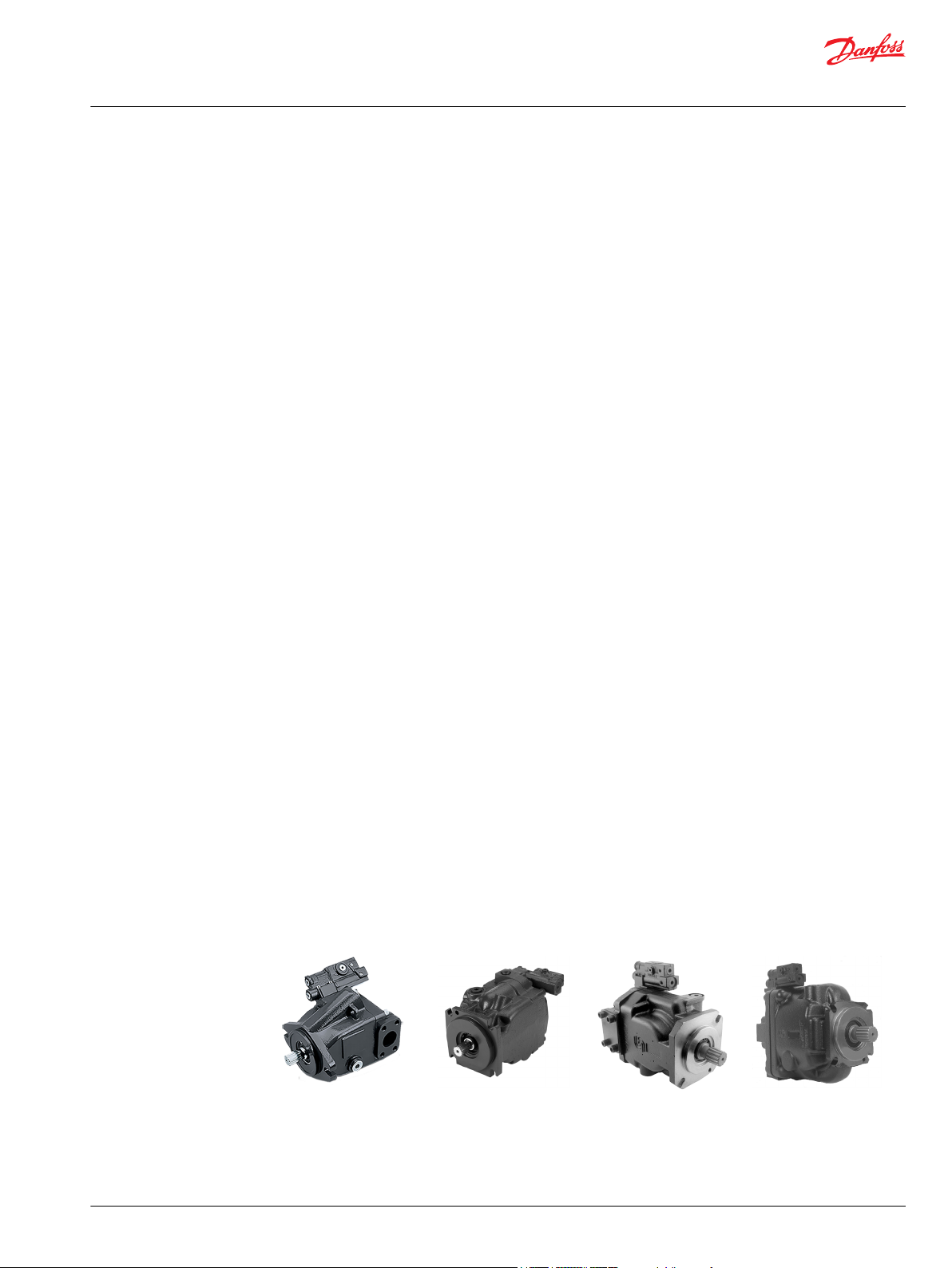
Basic units
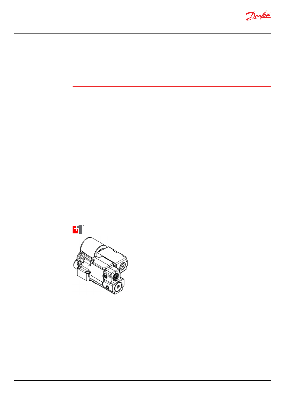
The series 45 family of open circuit, variable piston pumps, offers a range of displacements from 25 to 147
cm³/rev [1.53 to 8.97 in3/rev]. With maximum speeds up to 3600 rpm and continuous operating
pressures up to 310 bar [4495 psi], product selection is easily tailored to the flow and pressure
requirements of individual applications.
K2 Frame J Frame F Frame E Frame
©
Danfoss | January 2022 BC152886483703en-001201 | 9

Technical Information
Series 45 Pumps
General Information
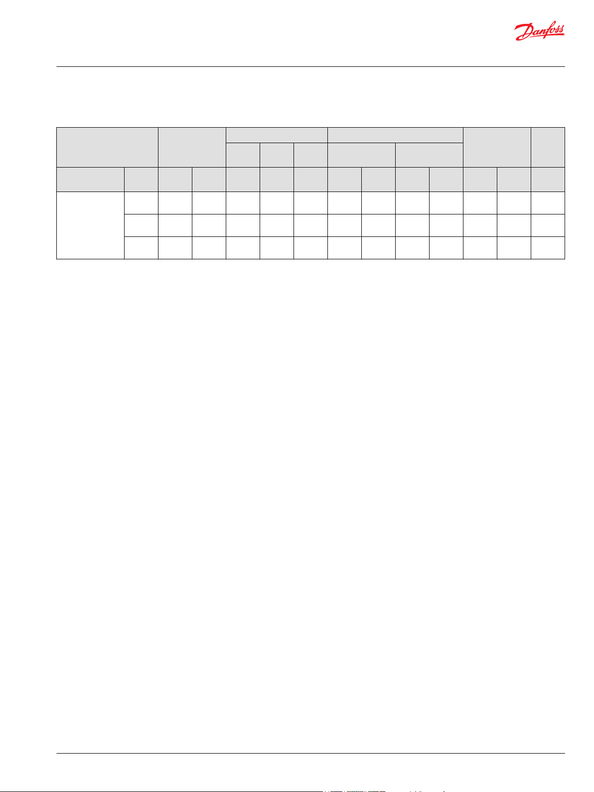
General performance specifications
Pump Displacement Speed Pressure Theoretical flow
Contin
Max. Min. Cont. Max.
(at rated speed)
uous
Frame Model cm
3
3
in
min
(rpm)
-1
min
(rpm)
-1
min
(rpm)
-1
bar psi bar psi US
gal/min
l/min Flange
Frame L L25C 25 1.53 3200 3600 500 260 3770 350 5075 21.0 80.0 SAE B -
L30D 30 1.83 3200 3600 500 210 3045 300 4350 25.4 96.0 SAE B -
Frame K K38C 38 2.32 2650 2800 500 260 3770 350 5075 26.6 100.7 SAE B -
K45D 45 2.75 2650 2800 500 210 3045 300 4350 31.5 119.3 SAE B -
Frame K2 K2-25C 25 1.53 3450 3750 500 260 3771 350 5076 22.8 86.3 SAE B -
K2-30C 30 1.83 3200 3450 500 25.4 96.0 SAE B -
K2-38C 38 2.32 2900 3050 500 29.1 110.2 SAE B -
K2-40C 40 2.44 3100 3200 500 34.5 124 SAE B -
K2-45C 45 2.75 2900 3050 500 34.5 130.5 SAE B -
Frame J J45B 45 2.75 2800 3360 500 310 4495 400 5800 33.3 126.0 SAE B 2-
J51B 51 3.11 2700 3240 500 310 4495 400 5800 36.4 137.7 SAE B 2-
J60B 60 3.66 2600 3120 500 310 4495 400 5800 41.2 156.0 SAE B 2-
J65C 65 3.97 2500 3000 500 260 3770 350 5075 42.9 162.6 SAE B 2-
J75C 75 4.58 2400 2880 500 260 3770 350 5075 47.5 180.0 SAE B 2-
Frame F F74B 74 4.52 2400 2800 500 310 4495 400 5800 46.9 177.6 SAE B 2-
F90C 90 5.49 2200 2600 500 260 3770 350 5075 52.3 198 SAE B 2-
Mounti
ng
2 bolt
2 bolt
2 bolt
2 bolt
2 bolt
2 bolt
2 bolt
2 bolt
2 bolt
bolt
SAE C 2
and 4bolt
bolt
SAE C 2
and 4bolt
bolt
SAE C 2
and 4bolt
bolt
SAE C 2
and 4bolt
bolt
SAE C 2
and 4bolt
bolt
SAE C 4bolt
bolt
SAE C 4bol
10 | © Danfoss | January 2022 BC152886483703en-001201
Technical Information
Series 45 Pumps
General Information
General performance specifications (continued)
Pump Displacement Speed Pressure Theoretical flow
Contin
uous
Frame Model cm
Frame E E100B 100 6.10 2450 2880 500 310 4495 400 5800 64.7 245.0 SAE C 4-
E130B 130 7.93 2200 2600 500 310 4495 400 5800 75.5 286.0 SAE C 4-
E147C 147 8.97 2100 2475 500 260 3770 350 5075 81.5 308.7 SAE C 4-
3
3
in
min
(rpm)
Max. Min. Cont. Max.
-1
min
(rpm)
-1
min
(rpm)
-1
bar psi bar psi US
(at rated speed)
l/min Flange
gal/min
Load sensing open circuit system
The pump receives fluid directly from the reservoir through the inlet line. A screen in the inlet line
protects the pump from large contaminants. The pump outlet feeds directional control valves such as
PVG-32’s, hydraulic integrated circuits (HIC), and other types of control valves. The PVG valve directs
pump flow to cylinders, motors and other work functions. A heat exchanger cools the fluid returning
from the valve. A filter cleans the fluid before it returns to the reservoir.
Flow in the circuit determines the speed of the actuators. The position of the PVG valve determines the
flow demand. A hydraulic pressure signal (LS signal) communicates demand to the pump control. The
pump control monitors the pressure differential between pump outlet and the LS signal, and regulates
servo pressure to control the swashplate angle. Swashplate angle determines pump flow.
Actuator load determines system pressure. The pump control monitors system pressure and will decrease
the swashplate angle to reduce flow if system pressure reaches the PC setting. A secondary system relief
valve in the PVG valve acts as a back-up to control system pressure.
Mounti
ng
bolt
bolt
bolt
©
Danfoss | January 2022 BC152886483703en-001201 | 11
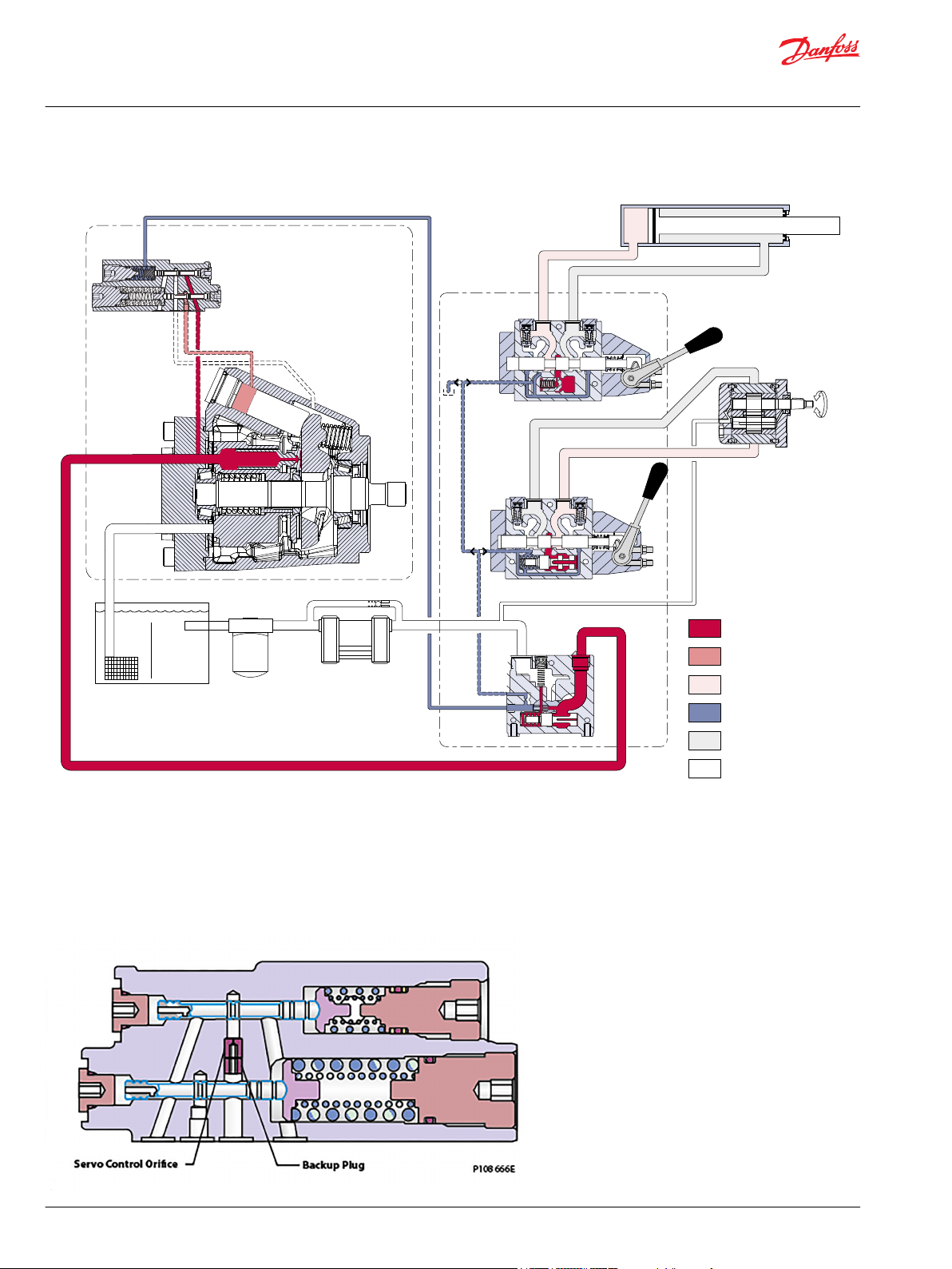
P109124
K2 Frame Series 45
open circuit axial
piston pump with
load sensing control
Reservoir
Filter
Heat exchanger
System pressur e
Servo pressur e
Actuator pressur e
Load sense pressur e
Actuator retur n
Suction / case drain /
system retur n
Double-ac ting cylinder
Bi-directional
gear moto r
PVG 32
mulit-sec tion
load
sensing
contro l
valve
Technical Information
Series 45 Pumps
General Information
Pictorial circuit diagram
Servo Control Orifice
Servo Control Orifice Principle
Series 45 controls offer an optional servo control orifice (not available with Pressure Compensation only
Controls) available to aid in tuning system performance. The optional servo control orifice restricts flow
to and from the servo system in the pump, effectively pacing the motion of the servo system.
12 | © Danfoss | January 2022 BC152886483703en-001201
P108 664E
0
50
100
150
200
250
300
350
System Pressure (bar)
Time
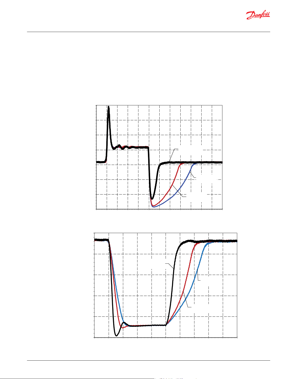
Relative Servo Control Orifice Performance
Generic PC Response and Recovery
Input Speed=1800rpm, Temperature=49°C, PC Setting=210Bar, LS Setting=20Bar
1.0mm Servo
Control Orifice
0.8mm Servo
Control Orifice
Without Servo
Control Orifice
0
50
100
150
200
250
System Pressure (bar)
Time
Relative Servo Control Orifice Performance
Generic LS Response and Recovery
Input Speed = 1800rpm, Temperature=49 C, PC Setting=310Bar, LS Setting=30Bar
0.8mm Servo
Control Orifice
1.0mm Servo
Control Orifice
Without Servo
Control Orifice
P108 665E
Technical Information
Series 45 Pumps
General Information
Servo Control Orifice Performance
The use of the Servo Control Orifice will provide additional pacing to the pump, while the response of the
pump to pressure spikes remains unaffected. The Pressure Compensation Function response and
recovery, as well as the Load Sense Function response and recovery are shown below, and outline the
relative impact in response and recovery of the Servo Control Orifices. Note that these graphs are meant
as a generic comparison only, and that unique effects on response and recovery behavior for each
specific frame are shown later in this section.
©
Danfoss | January 2022 BC152886483703en-001201 | 13
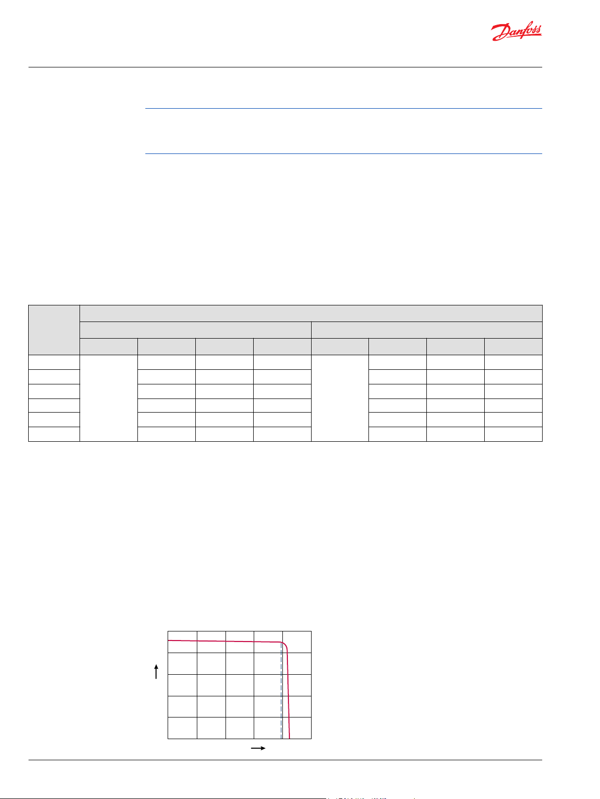
0
0
Q max
Pressure
Fl
ow
P101 166E
PC setting
Technical Information
Series 45 Pumps
General Information
We recommend that systems experiencing instability use a Servo Control Orifice. Start with the largest
size orifice available, and work down to the smaller size until the system is satisfactorily tuned. All FanDrive systems should start with a 0.8mm Servo Control Orifice if possible. Systems including motors are
more likely to require the Servo Control Orifice option.
Pacing Factor
Use of a Servo Control Orifice adds a pacing factor to each Series 45 Frame, impacting the behavior of the
pumps reactivity. This pacing factor can be multiplied by the specific Frame/Displacement/Control
selection’s response and recovery times, to determine the final paced response and recovery times.
Unique response and recovery times can be found in each frame-specific chapter, in the desired control
section. The paced response and recovery relationship is shown below.
Response (Damped)= Response (Specific Disp.Control) *Pacing Factor
Recovery (Damped)= Recovery (Specific Disp.Control) *Pacing Factor
Pacing Factors are unique to each orifice size, and can impact each frame differently. Below are the
Pacing Factors for each Servo Control Orifice Size by frame.
Frame Pacing Factors - Servo Control Orifice
1.0 mm Servo Control Orifice 0.8 mm Servo Control Orifice
PC Response PC Recovery LS Response LS Recovery PC Response PC Recovery LS Response LS Recovery
*
E-Frame
F-Frame
J-Frame
K2-Frame 2.3 2.0 2.0 3.2 2.6 2.6
K-Frame
L-Frame
*
PC Response from 160 bar to 210 bar, PC Recovery from 210 bar to 160 bar at 1800 rpm: LS Response from 230 bar to 30 bar, LS Recovery from 30 bar
to 230 bar at 1800 rpm.
**
** PC Response from 160 bar to 210 bar, PC Recovery from 210 bar to 160 bar at 1800 rpm: LS Response from 160 bar to 20 bar, LS Recovery from 20
bar to 160 bar at 1800 rpm.
Hydraulic Controls
*
*
**
**
1
(No Effect)
2.3 2.0 2.0 1
2.3 2.0 2.0 3.2 2.6 2.6
2.3 2.0 2.0 3.2 2.6 2.6
2.3 2.3 2.3 3.7 3.1 3.1
2.3 2.3 2.3 3.7 3.1 3.1
(No Effect)
3.2 2.6 2.6
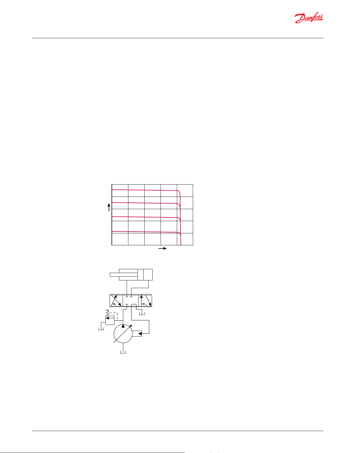
Pressure compensated controls
Operation
The PC control maintains constant system pressure in the hydraulic circuit by varying the output flow of
the pump. Used with a closed center control valve, the pump remains in high pressure standby mode at
the PC setting with zero flow until the function is actuated. This condition is often called a dead head
condition.
Typical operating curve
14 | © Danfoss | January 2022 BC152886483703en-001201
P101 965
W
Technical Information
Series 45 Pumps
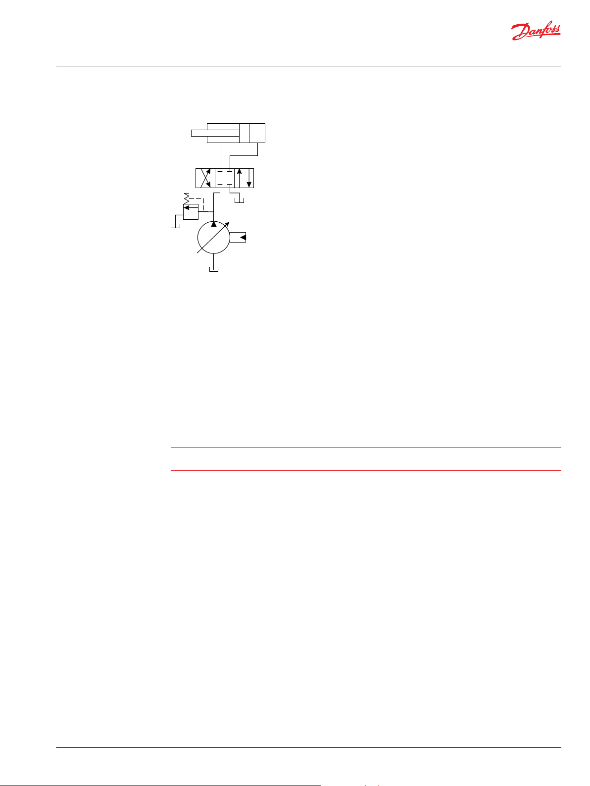
General Information
Simple closed-center circuit
Once the closed center valve is opened, the PC control senses the immediate drop in system pressure
and increases pump flow by increasing the swashplate angle. The pump continues to increase flow until
system pressure reaches the PC setting. If system pressure exceeds the PC setting, the PC control reduces
the swashplate angle to maintain system pressure by reducing flow. The PC control continues to monitor
system pressure and changes swashplate angle to match the output flow with the work function
pressure requirements.
If the demand for flow exceeds the capacity of the pump, the PC control directs the pump to maximum
displacement. In this condition, actual system pressure depends on the actuator load.
Each section includes control schematic diagrams, setting ranges, and response / recovery times for each
control available. Response is the time (in milliseconds) for the pump to reach zero displacement when
commanded by the control. Recovery is the time (in milliseconds) for the pump to reach full displacement
when commanded by the control. Actual times can vary depending on application conditions.
Warning
A relief valve is required to be installed in the pump outlet for additional system protection. Failure to
install a relief valve may lead to system damage and/or injury.
Pressure compensated system characteristics
Constant pressure and variable flow
•
High pressure standby mode when flow is not needed
•
System flow adjusts to meet system requirements
•
Single pump can provide flow to multiple work functions
•
Quick response to system flow and pressure requirements
•
Typical applications for pressure compensated systems
Constant force cylinders (bailers, compactors, refuse trucks)
•
On/off fan drives
•
Drill rigs
•
Sweepers
•
Trenchers
•
Remote pressure compensated controls
The remote PC control is a two-stage control that allows multiple PC settings. Remote PC controls are
commonly used in applications requiring low and high pressure PC operation.
©
Danfoss | January 2022 BC152886483703en-001201 | 15
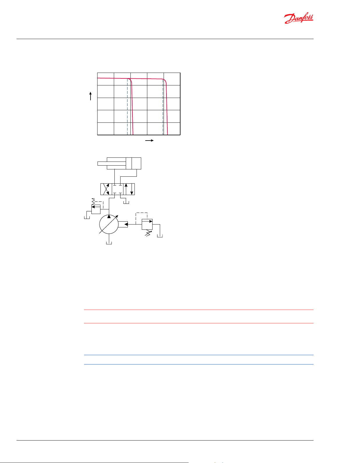
0
0
Q max
Pressure
Fl
ow
P101 969E
PC setting
Remote PC setting
P101 966
W
Technical Information
Series 45 Pumps
General Information
Typical operating curve
Closed center circuit with remote PC
The remote PC control uses a pilot line connected to an external hydraulic valve. The external valve
changes pressure in the pilot line, causing the PC control to operate at a lower pressure. When the pilot
line is vented to reservoir, the pump maintains pressure at the load sense setting. When pilot flow is
blocked, the pump maintains pressure at the PC setting. An on-off solenoid valve can be used in the pilot
line to create a low-pressure standby mode. A proportional solenoid valve, coupled with a
microprocessor control, can produce an infinite range of operating pressures between the low pressure
standby setting and the PC setting.
Warning
A relief valve is required to be installed in the pump outlet for additional system protection. Failure to
install a relief valve may lead to system damage and/or injury.
Each section includes control schematic diagrams, setting ranges, and response / recovery times for each
control available. Response is the time (in milliseconds) for the pump to reach zero displacement when
commanded by the control. Recovery is the time (in milliseconds) for the pump to reach full displacement
when commanded by the control. Actual times can vary depending on application conditions.
Size the external valve and plumbing for a pilot flow of 3.8 l/min [1 US gal/min].
Remote pressure compensated system characteristics
Constant pressure and variable flow
•
High or low pressure standby mode when flow is not needed
•
System flow adjusts to meet system requirements
•
Single pump can provide flow to multiple work functions
•
Quick response to system flow and pressure requirements
•
16 | © Danfoss | January 2022 BC152886483703en-001201
0
0
P101 968E
PC setting
Flow
Pressure
Q max
P101 967
Technical Information
Series 45 Pumps
General Information
Typical applications for remote pressure compensated systems
Modulating fan drives
•
Anti-stall control with engine speed feedback
•
Front wheel assist
•
Road rollers
•
Combine harvesters
•
Wood chippers
•
Load sensing controls
Operation
The LS control matches system requirements for both pressure and flow in the circuit regardless of the
working pressure. Used with a closed center control valve, the pump remains in low-pressure standby
mode with zero flow until the valve is opened. The LS setting determines standby pressure.
Typical operating curve
Load sensing circuit
Most load sensing systems use parallel, closed center, control valves with special porting that allows the
highest work function pressure (LS signal) to feed back to the LS control. Margin pressure is the difference
between system pressure and the LS signal pressure. The LS control monitors margin pressure to read
system demand. A drop in margin pressure means the system needs more flow. A rise in margin pressure
tells the LS control to decrease flow.
LS control with bleed orifice
The load sense signal line requires a bleed orifice to prevent high-pressure lockup of the pump control.
Most load-sensing control valves include this orifice. An optional internal bleed orifice is available, for use
with control valves that do not internally bleed the LS signal to tank.
©
Danfoss | January 2022 BC152886483703en-001201 | 17
W
Technical Information
Series 45 Pumps
General Information
Electric Controls
Integral PC function
The LS control also performs as a PC control, decreasing pump flow when system pressure reaches the PC
setting. The pressure compensating function has priority over the load sensing function.
Warning
A relief valve is required to be installed in the pump outlet for additional system protection. Failure to
install a relief valve may lead to system damage and/or injury.
Load sensing system characteristics
Variable pressure and flow
•
Low pressure standby mode when flow is not needed
•
System flow adjusted to meet system requirements
•
Lower torque requirements during engine start-up
•
Single pump can supply flow and regulate pressure for multiple circuits
•
Quick response to system flow and pressure requirements
•
Electric Proportional Controls (EPC)
PLUS+1® Compliance
All Series 45 Electric controls have met and passed the Danfoss PLUS+1® compliance standard testing,
and as such, this Series 45 control is PLUS+1® compliant. PLUS+1® compliance blocks are available on the
Danfoss website, within the PLUS+1® Guide section.
Electric Proportional Control Principle
The Electric Proportional Control consists of a proportional solenoid integrated into a Remote Pressure
Compensated control. This control allows the pump to be operated at any pressure limit between the
Load Sense and Pressure Compensation settings by varying the current sent to the solenoid.
18 | © Danfoss | January 2022 BC152886483703en-001201

Technical Information
Series 45 Pumps
General Information
Reference individual frame sections for the margin (LS) setting vs low pressure standby relationship.
Electric proportional controls have a unique relationship between margin (LS) setting and low pressure
standby. This relationship is available in the electric proportional controls section for each frame.
For fan-drive systems, and systems with motors, use a minimum 15bar LS setting to enhance system
stability. As the LS setting is reduced, the risk for system instability may be increased. A 20bar LS setting is
recommended as a starting point for all new applications.
Electric Proportional Control Response/Recovery
S45 Electric Proportional Controls require the use of a servo control orifice, and are available with two
possible servo control orifice options. The servo control orifice is used to enhance system stability, as well
as dampen the pump reactiveness. A smaller orifice diameter will add dampening to the pump
reactiveness, while a larger orifice will allow quicker pump reaction. Fan-Drive applications, as well as
systems with the pump supplying motors, are recommended to use the 0.8mm diameter orifice to
enhance system stability.
Module “G” Options for Electric Proportional Controls
Frame “E” - 0.8mm Orifice “F” - 1.0mm Orifice
All Frames
• •
Specific Electric Proportional Control Response/Recovery times are shown for the available servo control
orifice options in the control section within each specific frame section. These times represent the
response from 100bar to 200bar, and recovery from 200bar to 100bar. As the upper pressure approaches
the PC setting, the PC function will begin to assist in clipping pressure overshoots during the pump’s
response, and will decrease the response times of the pump to equal those of the PC response.
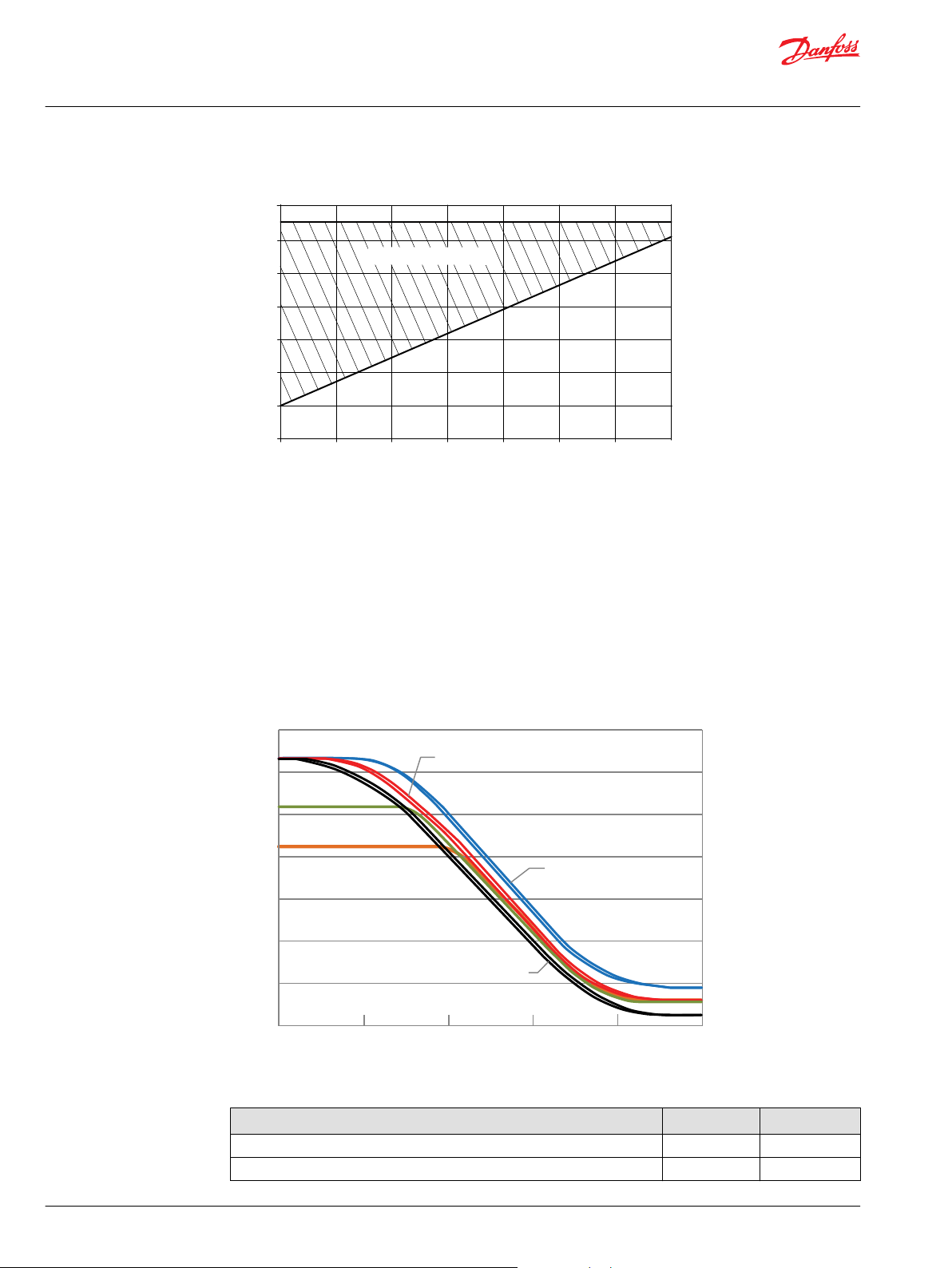
Electric Proportional Control Pressure vs. Flow Characteristic
The Electric Proportional Controls continuous duty operating temperature range is shown below; this
guideline should be followed as well as the maximum current limitations. Note that rated voltage refers
to either a 12V or 24V coil. Under high temperature conditions, current required to operate the solenoid
increases.
©
Danfoss | January 2022 BC152886483703en-001201 | 19
50
60
70
80
90
100
-40
100
Percent of Rated Voltage (%)
Ambient Temperature (°C)
P108 415E
-30
-20
-10
0
60
80
10
20
30
40
50
70
90
110
120
Operating Range
0
50
100
150
200
250
300
350
System Pressure (Bar)
0
0.2
0.4
0.6
0.8
1
Current proportion I/I max
310 Bar PC, 10 Bar LS
310 Bar PC, 20 Bar LS
310 Bar PC, 30 Bar LS
260 Bar PC, 20 Bar LS
210 Bar PC, 20 Bar LS
P108 657E
Technical Information
Series 45 Pumps
General Information
Continuous Duty Operating Temperature
Electric Proportional Control Characteristic – Normally Closed
When an electric current is sent to the Normally Closed configuration control, the pump pressure
decreases proportional to an increase in current. When the load in the system changes, the pump will
adjust its displacement to maintain the pressure demanded by the controlling current. This control is
especially useful for fan-drives, due to the direct relationship between fan-speed and pump pressure.
Due to the nature of Electric Proportional Controls, the relationship between current and pump pressure
is unique for each individual PC/LS pressure setting combination. The relationship between different PC
settings and different LS settings on the Pressure vs. Current Characteristic curve are shown below. The
hydraulic schematic for the Normally Closed Electric Proportional control is shown below as well.
Operating Pressure vs. Input Current (N.C. EPC)
20 | © Danfoss | January 2022 BC152886483703en-001201
Solenoid Data – Normally Closed
Voltage 12V 24V
Maximum Current 1800 mA 920 mA
Inrush Current 1700 mA 800 mA
Technical Information
Series 45 Pumps
General Information
Solenoid Data – Normally Closed (continued)
Voltage 12V 24V
Coil Resistance @ 20°C [70°F] 7.1 Ω 28.5 Ω
PWM Range 200-300 Hz
PWM Frequency (preferred) 250 Hz
IP Rating (IEC 60529 | DIN 40050-9) IP67 IP67
IP Rating (IEC 60529 | DIN 40050-9) with mating connector IP69K IP69K
Operating Temperature Consistent with Pump Limits:
-40°C (-40°F) to 104°C (220°F)
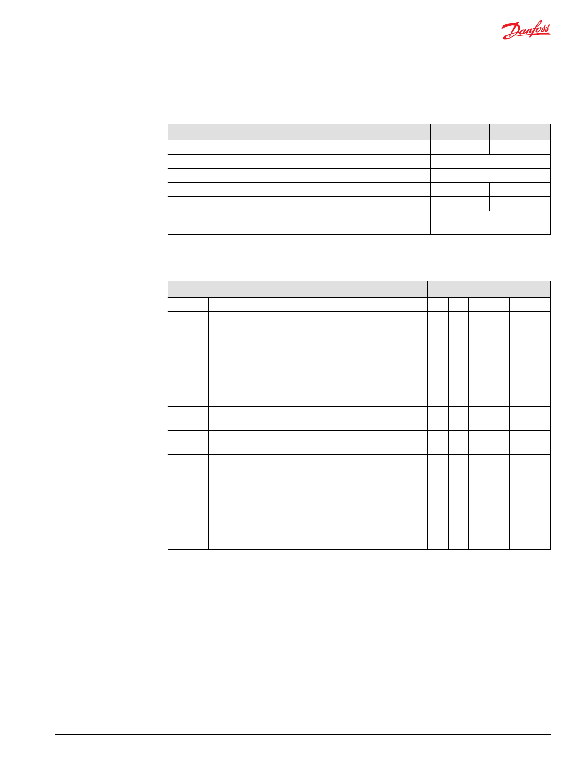
The available Normally Closed Electric Proportional Controls for the Series 45 are shown below. The
allowable Pressure Compensator (PC) and Load Sense (LS) pressure settings are provided for each frame
in their respective sections.
Electric Proportional Controls Options – Normally Closed Frame
Code Description L K
AH Electric Proportional Pressure Control w/Pressure Comp. (NC,
12VDC) Left
AL Electric Proportional Pressure Control w/Pressure Comp. (NC,
24VDC) Left
AV Electric Proportional Pressure Control w/Pressure Comp. (NC,
12VDC) Right
AK Electric Proportional Pressure Control w/Pressure Comp. (NC,
24VDC) Right
BH Electric Proportional Pressure Control w/Pressure Comp. (NC,
12VDC) [>280 bar] Left
BL Electric Proportional Pressure Control w/Pressure Comp. (NC,
24VDC) [>280 bar] Left
BM Electric Proportional Pressure Control w/Pressure Comp. (NC,
12VDC) [>280 bar] Right
BK Electric Proportional Pressure Control w/Pressure Comp. (NC,
24VDC) [>280 bar] Right
EM Electric Proportional Pressure Control w/Pressure Comp. (NC,
12VDC)
EN Electric Proportional Pressure Control w/Pressure Comp. (NC,
24VDC)
• •
• •
K2
J F E
• • • •
• • • •
• • •
• • •
• • •
• • •
• • •
• • •
Notes:
1. Left = E-Frame: CW Only, F-Frame: CW Only, J-frame: CW Axial, CCW Radial
2. Right = E-Frame: CCW Only, F-Frame: CCW Only, J-frame: CCW Axial, CW Radial
3. K/L Frame Controls are not rotation dependent
4. K2 Frame electric controls are limited only for Left orientation and up to 260 Bar
Electric Proportional Control Characteristic – Normally Open
When an electric current is sent to the normally open configuration control, the pump pressure increases
proportional to an increase in current. When the load in the system changes, the pump will adjust its
displacement to maintain the pressure demanded by the controlling current. This control is especially
useful for fan-drives, due to the direct relationship between fan-speed and pump pressure.
Due to the nature of Electric Proportional Controls, the relationship between current and pump pressure
is unique for each individual PC/LS pressure setting combination. The relationship between different PC
©
Danfoss | January 2022 BC152886483703en-001201 | 21
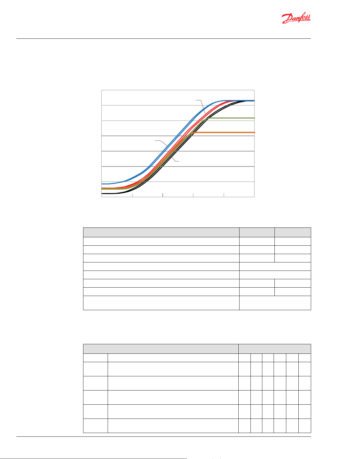
0
50
100
150
200
250
300
350
System Pressure (Bar)
0
0.2
0.4
0.6
0.8
1
260 Bar PC, 20 Bar LS
210 Bar PC, 20 Bar LS
310 Bar PC, 20 Bar LS
310 Bar PC, 30 Bar LS
310 Bar PC, 10 Bar LS
P108 658E
Current proportion I/I max
Technical Information
Series 45 Pumps
General Information
settings and different LS settings on the Pressure vs. Current Characteristic curve are shown below. The
hydraulic schematic for the Normally Open Electric Proportional control is shown below as well.
Operating Pressure vs. Input Current (N.O. EPC)
Solenoid Data – Normally Open
Voltage 12V 24V
Maximum Current 1500 mA 665 mA
Inrush Current 1700 mA 800 mA
Coil Resistance @ 20°C [70°F] 7.1 Ω 28.5 Ω
PWM Range 200-300 Hz
PWM Frequency (preferred) 250 Hz
IP Rating (IEC 60529 | DIN 40050-9) IP67 IP67
IP Rating (IEC 60529 | DIN 40050-9) with mating connector IP69K IP69K
Operating Temperature Consistent with Pump Limits:
-40°C (-40°F) to 104°C (220°F)
The available Normally Open Electric Proportional Controls for the Series 45 are shown below. The
allowable Pressure Compensator (PC) and Load Sense (LS) pressure settings are provided for each frame
in their respective sections. Note that for Electric Proportional Controls, the Load Sense setting describes
the Low Pressure Standby value, not margin.
Electric Proportional Controls Options – Normally Open Frame
Code Description L K
AX Electric Proportional Pressure Control w/Pressure Comp. (NO,
12VDC) Left
CL Electric Proportional Pressure Control w/Pressure Comp. (NO,
24VDC) Left
AW Electric Proportional Pressure Control w/Pressure Comp. (NO,
12VDC) Right
CK Electric Proportional Pressure Control w/Pressure Comp. (NO,
24VDC) Right
BX Electric Proportional Pressure Control w/Pressure Comp. (NO,
12VDC) [>280 bar] Left
K2
J F E
• • • •
• • • •
• • •
• • •
• • •
22 | © Danfoss | January 2022 BC152886483703en-001201
Technical Information
Series 45 Pumps
General Information
Electric Proportional Controls Options – Normally Open Frame
DL Electric Proportional Pressure Control w/Pressure Comp. (NO,
24VDC) [>280 bar] Left
BW Electric Proportional Pressure Control w/Pressure Comp. (NO,
12VDC) [>280 bar] Right
DK Electric Proportional Pressure Control w/Pressure Comp. (NO,
24VDC) [>280 bar] Right
EK Electric Proportional Pressure Control w/Pressure Comp. (NO,
12VDC)
EL Electric Proportional Pressure Control w/Pressure Comp. (NO,
24VDC)
• •
• •
Notes:
1. Left = E-Frame: CW Only, F-Frame: CW Only, J-frame: CW Axial, CCW Radial
2. Right = E-Frame: CCW Only, F-Frame: CCW Only, J-frame: CCW Axial, CW Radial
3. K/L Frame Controls are not rotation dependent
4. K2 Frame electric controls are limited only for Left orientation and up to 260 Bar
Electric On-Off Controls
• • •
• • •
• • •
PLUS+1 Compliance
All Series 45 Electric controls have met and passed the Danfoss PLUS+1 compliance standard testing, and
as such, this Series 45 control is PLUS+1 compliant. PLUS+1 compliance blocks are available on the
Danfoss website, within the PLUS+1 Guide section.
Electric On-Off Control Principle
The Electric On/Off Control consists of an On/Off solenoid integrated into a Remote Pressure
Compensated control. This control allows the pump to be operated at either the Load Sense pressure
setting when “On”, or the Pressure Compensation pressure setting when “Off”.
©
Danfoss | January 2022 BC152886483703en-001201 | 23
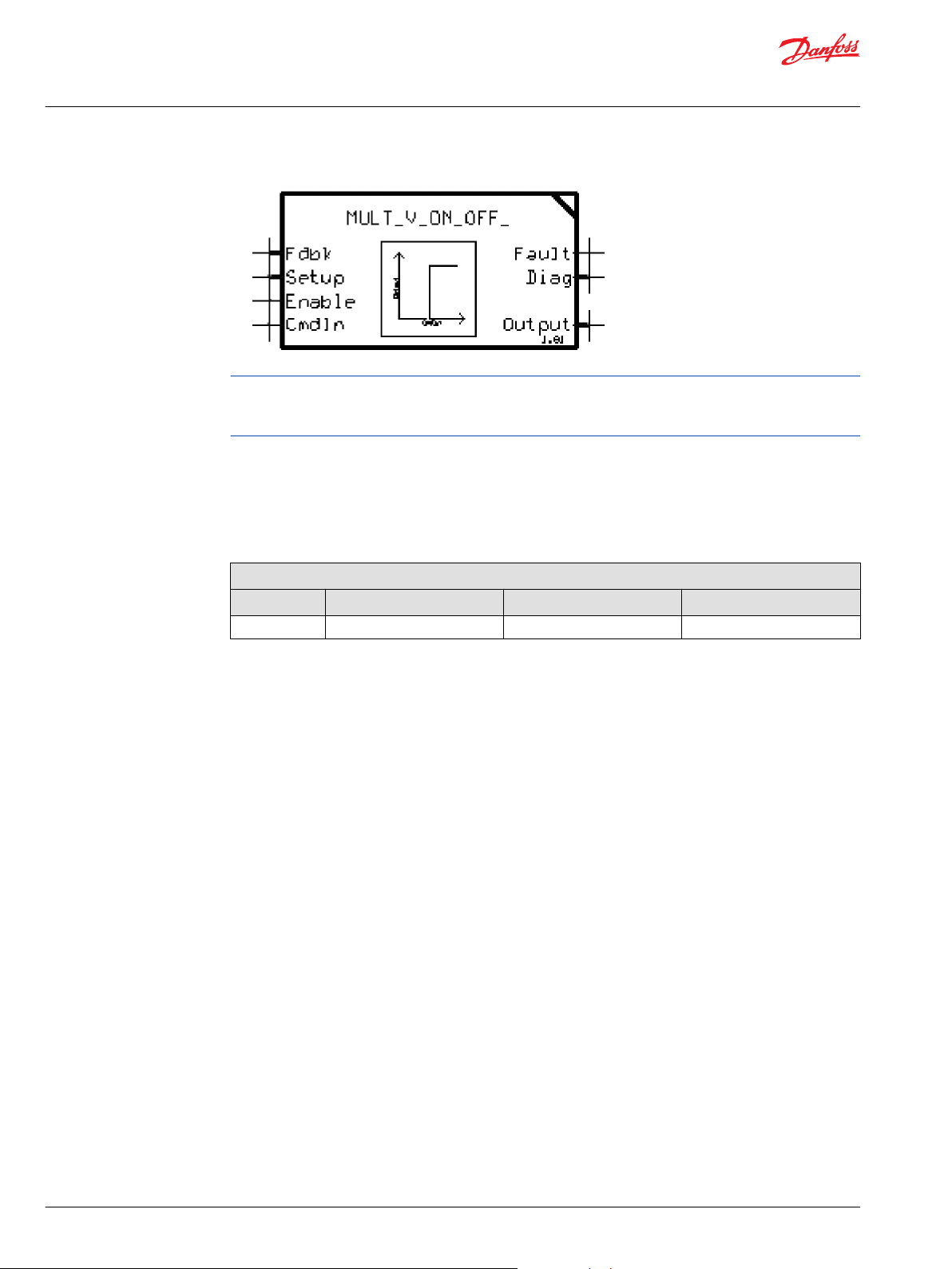
Technical Information
Series 45 Pumps
General Information
For fan-drive systems, and systems with motors, use a minimum 15bar LS setting to enhance system
stability. As the LS setting is reduced, the risk for system instability may be increased. A 20bar LS setting is
recommended as a starting point for all new applications.
Electric On-Off Control Response/Recovery
S45 Electric On/Off Controls are available with two servo control orifice options, as well as without an
orifice. The servo control orifice is used to enhance system stability, as well as dampen the pump
reactiveness. A smaller orifice diameter will add dampening to the pump reactiveness, while a larger
orifice will allow quicker pump reaction.
Module “G” Options for Electric On/Off Controls
Frame “E” - 0.8mm Orifice “F” - 1.0mm Orifice “N” - No Orifice
All Frames
• • •
Specific Electric On/Off Control Response/Recovery times are shown for the available servo control orifice
options in the control section within each specific frame section. These times represent the response
from 75% of rated continuous pressure to 100% of rated continuous pressure, and recovery from 100% of
rated continuous pressure to 75% of rated continuous pressure for N.C. configuration per SAE J745 (viceversa for N.O). As the system pressure approaches the PC setting, the PC function will begin to assist in
clipping pressure overshoots during the pump’s response, and will decrease the response times of the
pump to equal those of the PC response.
Electric On-Off Control Performance vs. Ambient Temperature Characteristic
The Electric On/Off Controls continuous duty operating temperature range is shown below; this guideline
should be followed as well as the maximum current limitations. Note that rated voltage refers to either a
12V or 24V coil. Under high temperature conditions the PWM duty cycle to operate the solenoid
increases.
24 | © Danfoss | January 2022 BC152886483703en-001201
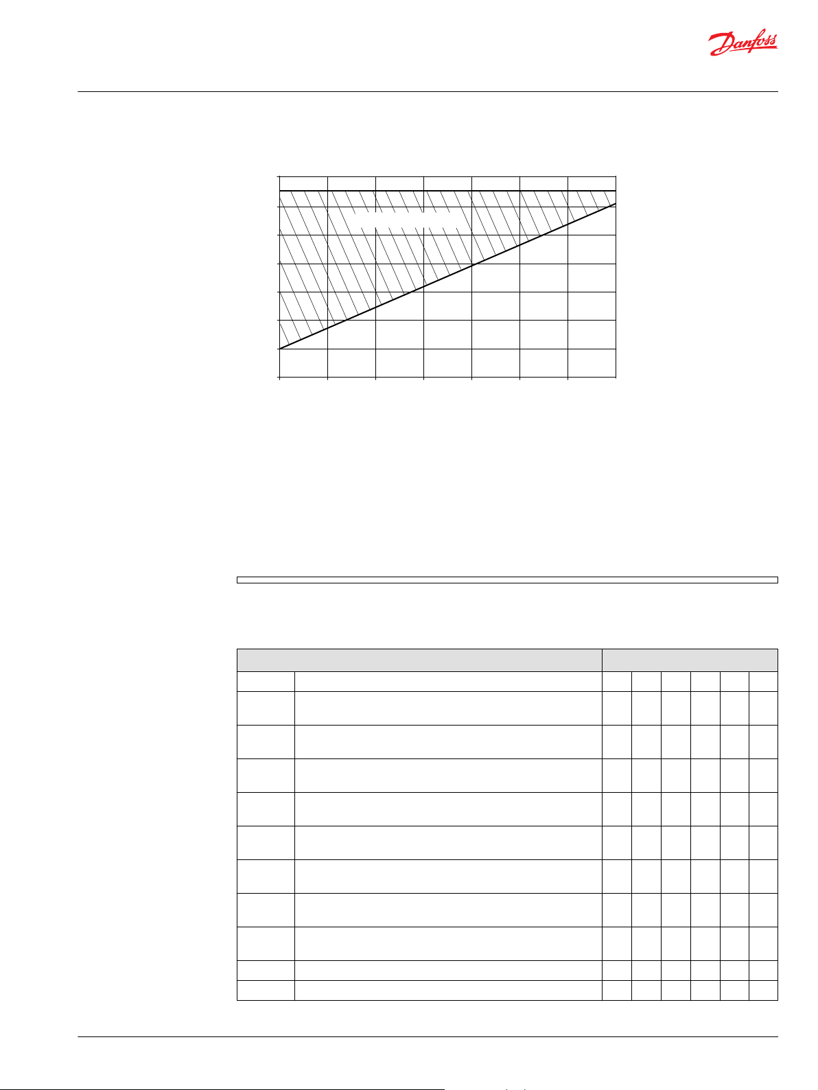
50
60
70
80
90
100
-40
100
Percent of Rated Voltage (%)
Ambient Temperature (°C)
P108 415E
-30
-20
-10
0
60
80
10
20
30
40
50
70
90
110
120
Operating Range
Technical Information
Series 45 Pumps
General Information
Continuous Duty Operating Temperature
Electric On-Off Control Characteristic – Normally Closed
The normally closed configuration On/Off control directs the pump to its Pressure Compensation
pressure setting when no current is applied. When the required electric current is sent to the normally
closed configuration control the pump pressure decreases to the Low-Pressure Standby setting. This
control does not have Load Sense functionality, but rather acts as a Pressure Compensation control when
not energized, or is directed to its low-pressure standby when energized. This control is especially useful
for machine startups, as the pump can be directed to its Low-Pressure Standby setting during startup to
reduce the load on engine starters.
The available Normally Closed Electric On/Off Controls for the Series 45 are shown below. The allowable
Pressure Compensator (PC) and Load Sense (LS) pressure settings are provided for each frame in their
respective sections.
Electric On/Off Controls Options – Normally Closed Frame
Code Description L K
AR Electric On/Off Pressure Control w/Pressure Comp. (NC,12VDC)
Left
CR Electric On/Off Pressure Control w/Pressure Comp. (NC,24VDC)
Left
AG Electric On/Off Pressure Control w/Pressure Comp. (NC,12VDC)
Right
AY Electric On/Off Pressure Control w/Pressure Comp. (NC,24VDC)
Right
BR Electric On/Off Pressure Control w/Pressure Comp. (NC,12VDC)
[>280 bar] Left
DR Electric On/Off Pressure Control w/Pressure Comp. (NC,24VDC)
[>280 bar] Left
BE Electric On/Off Pressure Control w/Pressure Comp. (NC,12VDC)
[>280 bar] Right
BG Electric On/Off Pressure Control w/Pressure Comp. (NC,24VDC)
[>280 bar] Right
EB Electric On/Off Pressure Control w/Pressure Comp. (NC,12VDC)
EE Electric On/Off Pressure Control w/Pressure Comp. (NC,24VDC)
• •
• •
K2
J F E
• • • •
• • • •
• • •
• • •
• • •
• • •
• • •
• • •
Notes:
©
Danfoss | January 2022 BC152886483703en-001201 | 25
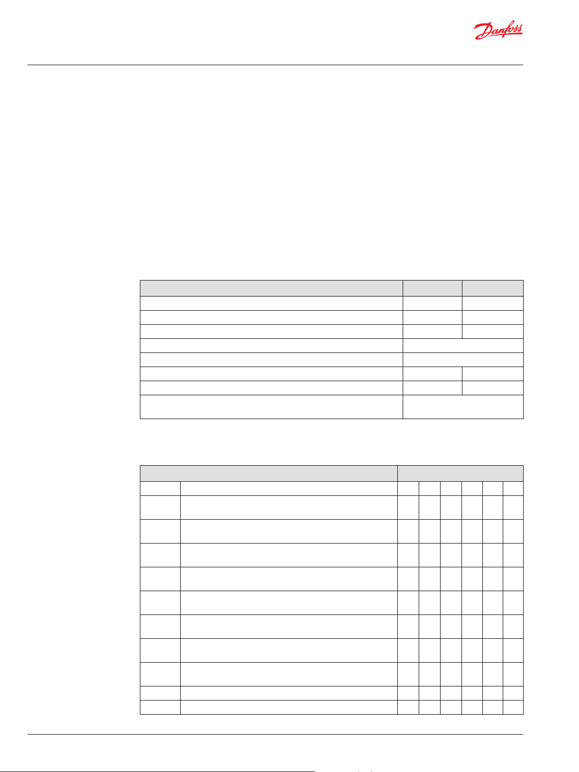
Technical Information
Series 45 Pumps
General Information
1. Left = E-Frame: CW Only, F-Frame: CW Only, J-frame: CW Axial, CCW Radial
2. Right = E-Frame: CCW Only, F-Frame: CCW Only, J-frame: CCW Axial, CW Radial
3. K/L Frame Controls are not rotation dependent
4. K2 Frame electric controls are limited only for Left orientation and up to 260 Bar
Electric On/Off Control Characteristic – Normally Open
The Normally Open configuration On/Off control directs the pump to its Low-Pressure Standby setting
when no current is applied. When the required electric current (end current) is sent to the Normally Open
configuration control, the pump pressure increases to the Pressure Compensation pressure setting. This
control does not have Load Sense functionality, but rather acts as a Pressure Compensation control when
energized, or is directed to its Low-Pressure Standby when de-energized. This control is especially useful
for machine startups, as the pump can be directed to its Low Pressure Standby setting during startup to
reduce the load on engine starters.
Solenoid Data – Normally Open
Voltage 12V 24V
Maximum Current 1500 mA 665 mA
Inrush Current 1700 mA 800 mA
Coil Resistance @ 20°C [70°F] 7.1 Ω 28.5 Ω
PWM Range 200-300 Hz
PWM Frequency (preferred) 250 Hz
IP Rating (IEC 60529 | DIN 40050-9) IP67 IP67
IP Rating (IEC 60529 | DIN 40050-9) with mating connector IP69K IP69K
Operating Temperature Consistent with Pump Limits:
-40°C (-40°F) to 104°C (220°F)
The available Normally Open Electric On/Off Controls for the Series 45 Frame E are shown below, with the
allowable Pressure Compensator (PC) pressure range provided for each control. All Electric On/Off
Controls are available with the 10-40bar Load Sense (LS) setting range.
Electric On/Off Controls Options – Normally Open Frame
Code Description L K
AN Electric On/Off Pressure Control w/Pressure Comp. (NO,12VDC)
Left
CN Electric On/Off Pressure Control w/Pressure Comp. (NO,24VDC)
Left
AF Electric On/Off Pressure Control w/Pressure Comp. (NO,12VDC)
Right
AT Electric On/Off Pressure Control w/Pressure Comp. (NO,24VDC)
Right
BN Electric On/Off Pressure Control w/Pressure Comp. (NO,12VDC)
[>280 bar] Left
DN Electric On/Off Pressure Control w/Pressure Comp. (NO,24VDC)
[>280 bar] Left
BF Electric On/Off Pressure Control w/Pressure Comp. (NO,12VDC)
[>280 bar] Right
DF Electric On/Off Pressure Control w/Pressure Comp. (NO,24VDC)
[>280 bar] Right
EA Electric On/Off Pressure Control w/Pressure Comp. (NO,12VDC)
EG Electric On/Off Pressure Control w/Pressure Comp. (NO,24VDC)
• •
• •
K2
J F E
• • • •
• • • •
• • •
• • •
• • •
• • •
• • •
• • •
26 | © Danfoss | January 2022 BC152886483703en-001201
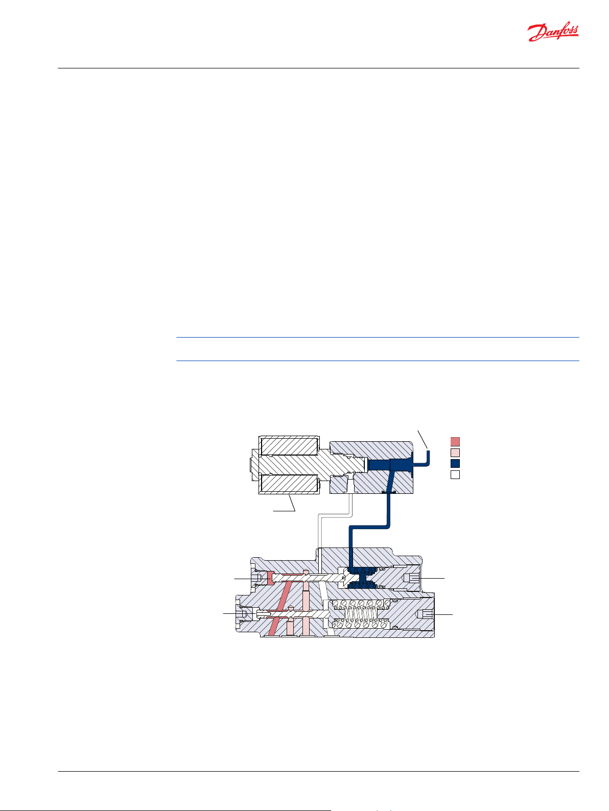
P108589
System pressure
Load Sense Pressure
Servo pressure
Drain
LS adjustment
PC adjustment
LS spool
PC spool
Solenoid
Load sensing connection
for dump and ETL controls
Technical Information
Series 45 Pumps
General Information
Notes:
1. Left = E-Frame: CW Only, F-Frame: CW Only, J-frame: CW Axial, CCW Radial
2. Right = E-Frame: CCW Only, F-Frame: CCW Only, J-frame: CCW Axial, CW Radial
3. K/L Frame Controls are not rotation dependent
4. K2 Frame electric controls are limited only for Left orientation and up to 260 Bar
Electric dump valve PC/LS controls
The electric dump valve pressure-compensated/load sense control allows the pump to operate as a
PC/LS type control under normal operating conditions. The solenoid dump valve overrides the LS control,
allowing the pump to operate in a Low-Pressure Standby mode. This function provides reduced
horsepower and torque loss in certain situations. It may be particularly useful to reduce loads on a system
during engine start.
When closed, the solenoid valve allows the control to act as a PC/LS control. When open, the solenoid
valve allows flow from the incoming load sense pressure to dump to case. This reduces the pressure in
the LS spring cavity, shifting the LS spool, and allows the pump to de-stroke to the Low-Pressure Standby
condition. This control is for applications needing a PC/LS control with the ability to switch to LowPressure Standby electronically. The solenoid valve is available in a normally closed and open
configuration.
For high cycling or power management applications, ensure to limit margin pressures to 60 bar or less for
optimal control component life.
Refer to LS System Over-Signaling on page 50 for more details.
Electric Dump Control (frames E, F and J)
Electronic Torque Limiting Controls (ETL)
PLUS+1 Compliance
All controls for this product have met and passed the Danfoss PLUS+1® compliance standard testing, and
as such, this product control is PLUS+1® Compliant. PLUS+1® compliance blocks (software) are available
on the Danfoss website, |
©
Danfoss | January 2022 BC152886483703en-001201 | 27
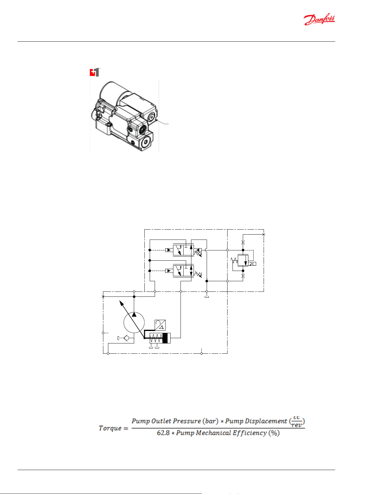
ETL load sense
connection port
P108779
S
M2
X
B
(ETL Signal
Port)
Technical Information
Series 45 Pumps
General Information
Electric Torque Limiting Control Principle
The Electronic Torque Limiting control consists of a normally closed proportional relief valve (PRV)
integrated into a Pressure Compensated/Load Sensing control. This control operates as a PC/LS control,
with the additional ability to limit load sense pressure using the integrated PRV by varying the current to
the solenoid. When combined with an angle sensor, this control allows for a PC/LS control with electronic
torque limiting.
J-frame pump with integrated ETL control
Pump torque consumption is a function of pump outlet pressure, pump displacement, and pump
mechanical efficiency. When pump mechanical efficiency is considered constant, the pump torque can
be limited when pump displacement is known and pump pressure is controlled. As pump displacement
increases, the pump outlet pressure can be limited using the PRV to result in a constant torque limit.
Pump outlet pressure is equal to the load sense pressure, which is limited with the PRV, plus the margin
pressure setting of the pump.
28 | © Danfoss | January 2022 BC152886483703en-001201
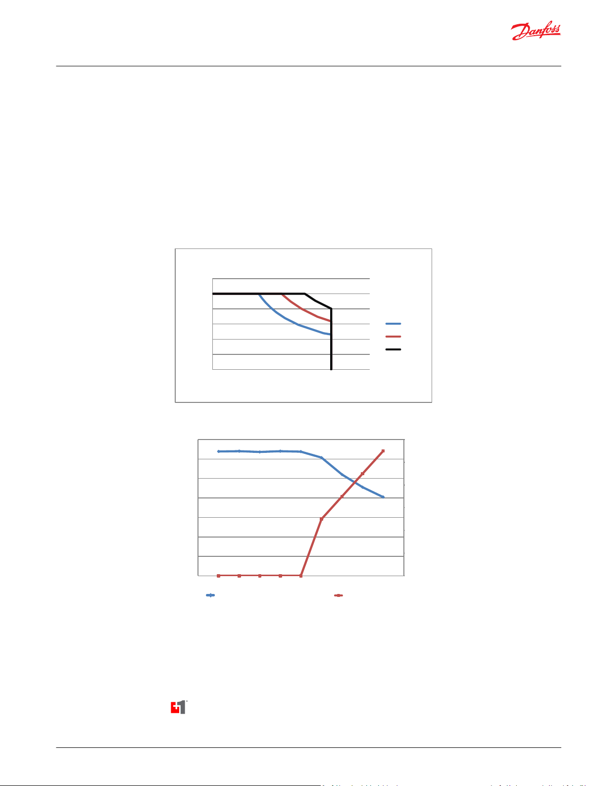
0
50
100
150
200
250
300
0 50 100 150 200
Pump Pressure (bar)
Pump Displacement (cc)
Electronic Torque Limiting
Speed 1
Speed 2
Speed 3
P108783
0
100
200
300
400
500
600
0
50
100
150
200
250
300
350
0 5 10 15 20 25 30 35 40 45
50
Basic ETL Control Logic
P108785
Current to Valve (mA)
Current to Valve (mA)
Maximum System Pressure - ETL Active (bar)
Pump Displacement (cc)
Maximum System Pressure (bar)
Technical Information
Series 45 Pumps
General Information
Electronic Torque Limiting Control Characteristic
The Electronic Torque Limiting control allows users to limit pump torque consumption electronically by
combining a pressure limiting PRV and angle sensor. This torque limit can be changed with varying
engine speeds (as shown in the Electronic Torque Limiting graph below), allowing the use of full engine
torque at all engine speeds and increasing machine productivity. A microcontroller is required to store
engine torque vs speed, receive the pump angle sensor signal, and then calculate and output the pump
outlet pressure limit. The basic torque limiting control logic for a single engine speed is shown below.
Danfoss offers a PLUS+1 subsystem application block for the Electronic Torque Limiting control option in
combination with keyed MC012-112 microcontroller hardware. The part number for the keyed
MC012-112 microcontroller is 11157484. Refer to graph Operating Pressure vs. Input Current (N.C. EPC) on
page 20 for pressure vs. current information.
©
Fan Drive Control (FDC)
PLUS+1 Compliance
All Series 45 Electric controls have met and passed the Danfoss PLUS+1 compliance standard testing, and
as such, this Series 45 control is PLUS+1 compliant. PLUS+1 compliance blocks (software) are available on
the Danfoss website, within the PLUS+1 Guide section.
Danfoss | January 2022 BC152886483703en-001201 | 29
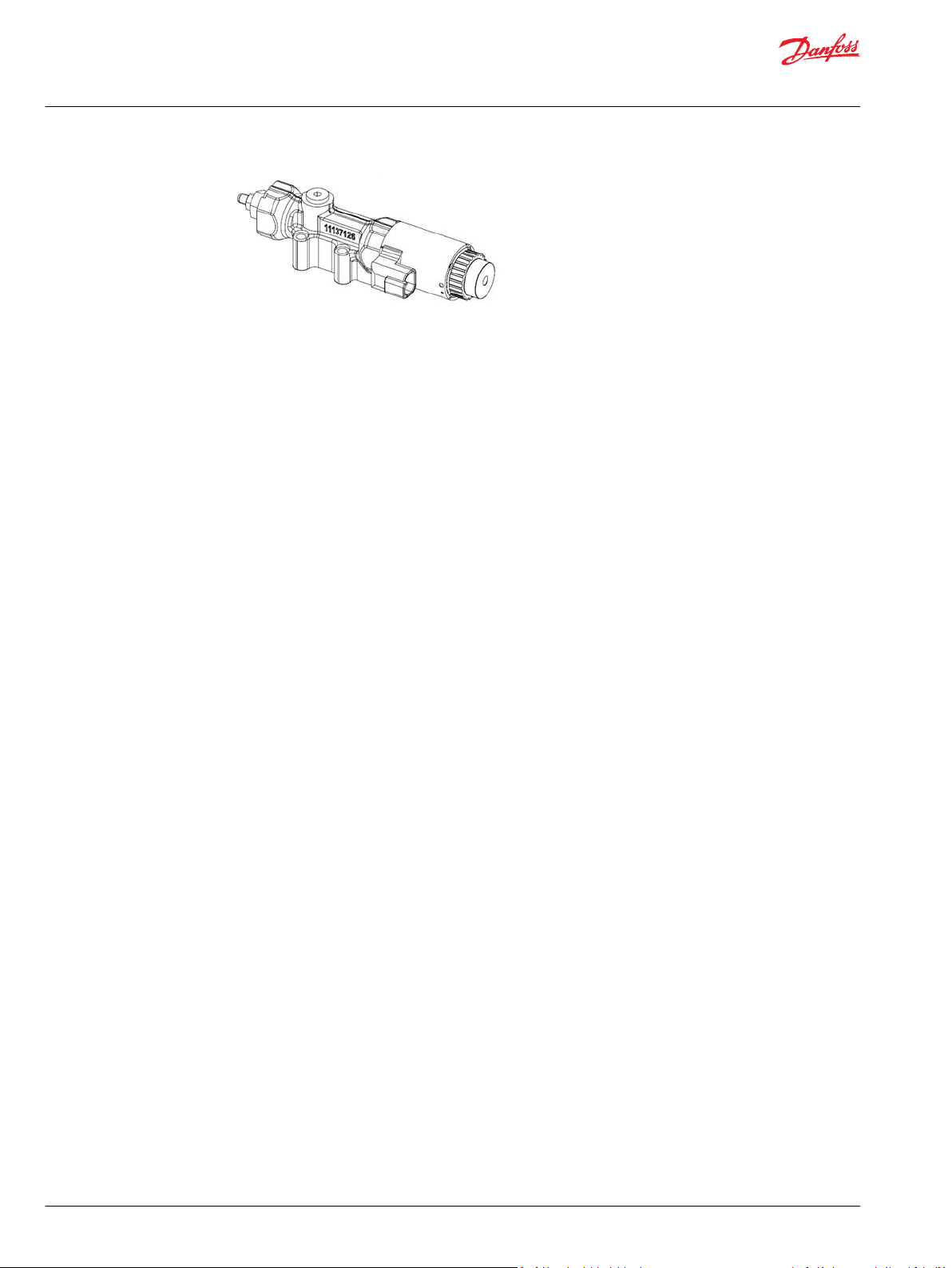
Technical Information
Series 45 Pumps
General Information
30 | © Danfoss | January 2022 BC152886483703en-001201

W
W
Technical Information
Series 45 Pumps
General Information
Fan Drive Control Principle
The Fan Drive Control is a unique electrically actuated pressure control solution that consists of a
normally closed proportional solenoid and one dual diameter spool sliding in the control housing.
System pressure acts on an area between the two spool diameters of the spool lands. This hydraulic force
is balanced with forces of springs and the solenoid when the spool is in the metering position. When no
current is sent to the solenoid it operates the pump at or below the PC setting which is adjusted
mechanically with the adjustor screw and lock nut. Increasing the control current proportionally reduces
the pump's outlet pressure until a minimum standby pressure is reached.
Control Block 12V and 24V
The minimum system pressure is given by swashplate moments of the pump and by servo system
leakages which produce a pressure drop across the control. In addition, fan motor type and fan inertia
impact minimum system pressure.
The Normally Closed Fan Drive Control coupled with a microprocessor allows the pump to operate at an
infinite range of operating pressures between a minimum system pressure and PC setting.
Warning
A relief valve is required to be installed in the pump outlet for additional system protection. Failure to
install a relief valve may lead to system damage and/or injury.
Warning
The Fan Drive Control is intended for fan drive systems only! Use in other systems could result in system
component damage or unintended machine movement. The Fan Drive Control is not intended to serve
at the primary system pressure relief. Loss of the input signal to this control will cause the pump to
produce maximum flow.
Fan Drive Control System Characteristics
•
Constant pressure and variable flow
•
High or low system pressure mode based on fan cooling demand
•
System flow adjusts to meet system requirements
©
Danfoss | January 2022 BC152886483703en-001201 | 31

P109029
0
50
100
150
200
250
300
350
0 100 200 300 400 500 600 700 800
PC310bar PC260bar PC210bar PC140bar PC100bar
Solenoid Input Current (mA)
Pump Outlet Pressure (bar)
Technical Information
Series 45 Pumps
General Information
Unintended Applications for Fan Drive Control Systems
•
Applications with frequent PC events (system pressure overshoots)
•
Adjustable Load Sensing systems
Fan Drive Control Cross Section
Fan Drive Control characteristic - Normally Closed
When an electric current is sent to the Normally Closed Fan Drive Control, pump outlet pressure
decreases proportionally to the increase in currentt. When the load in the system changes, the pump will
adjust its displacement to maintain the pressure demanded by the controlling current. This predictable
control is especially useful for fan-drive systems, due to the direct relationship between fan-speed and
pump pressure. Due to the nature of the Fan Drive Control, the relationship between current and pump
pressure is unique for each individual PC pressure setting combination. The relationship between pump
outlet pressure and control input current (for a 24V coil) is shown for various PC settings below. The
hydraulic schematic for the Normally Closed Fan Drive Control is shown below as well.
Pump Outlet Pressure vs. control input current 24V Normally closed FDC (at 100Hz PWM)
32 | © Danfoss | January 2022 BC152886483703en-001201

0
50
100
150
200
250
300
350
0 200 400 600 800 10 00 1200 1400 1600
PC310bar PC260bar PC210bar PC140bar
P109028
PC100bar
Solenoid Input Current (mA)
Pump Outlet Pressure (bar)
M2
L2
S
L1
P109315
B
Legend
B
S
L1, L2
M2
= Outlet
= Inlet
= Case drain
= System pressure
gauge port
Gain
Orifice
Choke
Orifice
Technical Information
Series 45 Pumps
General Information
Pump Outlet Pressure vs. control input current 12V Normally closed FDC (at 100Hz PWM)
Attaining remarkably low system pressures is possible with the Fan Drive Control. The minimum system
pressure is greatly dependent on individual system parameters such as fan motor type and fan size. This
feature is highly desirable in low cooling demand conditions to keep fan speed as slow as possible.
Virtually eliminated control deadband increases controllability and reduces power loss. Control current
resolution is greatly improved.
S45 pump with integrated FDC control Schematic
©
Danfoss | January 2022 BC152886483703en-001201 | 33
Solenoid data – Normally closed
Solenoid Data – Normally Closed
Connector on solenoid Deutsch DT04-2P
Mating Connector (not included) Deutsch DT06-2S
12V 24V

Technical Information
Series 45 Pumps
General Information
Solenoid Data – Normally Closed (continued)
12V 24V
Identification by color of nut Black Blue
Nominal current 1650 mA 840 mA
Maximum Control Current 1800 mA 920 mA
Environmental rating IP67 without mating connector,
IP69K with mating connector
Maximum output driver current 2.0 Amps
PLUS+1 dither frequency Not recommended
Useable PWM Frequency Range 50-200 Hz
Recommended PWM Frequency 200 Hz
Nominal Resistance at 20°C 3.66 Ω 14.2 Ω
Inductivity (pin at stroke end) 33 mH 140 mH
Minimum voltage 9.5 Vdc 19.0 Vdc
Maximum power 17.9 Watts 18.1 Watts
The Fan Drive Control is designed as a current driven control. It requires a PWM- input signal.
34 | © Danfoss | January 2022 BC152886483703en-001201

Technical Information
Series 45 Pumps
General Information
Fan Drive Control configuration
The available Normally Closed Fan Drive Controls for Series 45 are shown below. The allowable Pressure
Compensator (PC) pressure settings are provided for each frame.
C module—Control
Fan Drive Control Options Frame
Code Description L K K2 J F E
SA Fan Drive Control (12Vdc), 100-210 Bar, Left • • •
SB Fan Drive Control (24Vdc), 100-210 Bar, Left • • •
SC Fan Drive Control (12Vdc), 220-310 Bar, Left • • •
SD Fan Drive Control (24Vdc), 220-310 Bar, Left • • •
SE Fan Drive Control (12Vdc), 100-210 Bar, Right • •
SF Fan Drive Control (24Vdc), 100-210 Bar, Right • •
SG Fan Drive Control (12Vdc), 220-310 Bar, Right • •
SH Fan Drive Control (24Vdc), 220-310 Bar, Right • •
G module options—Choke Orifice
Fan Drive Control options Choke Orifice size
G 0.8 mm (0.031 in)
F 1.0 mm (0.039 in
Angle Sensor
H module options—Gain Orifice
Fan Drive Control options Gain Orifice Size
E 1.2 mm (0.047 in)
NC Fan Drive Control 3D Views
Left Right
PLUS+1 Compliance
The Electric Angle Sensor has met and passed the Danfoss PLUS+1 compliance standard testing, and as
such, this Angle Sensor is PLUS+1 compliant. PLUS+1 compliance blocks are available on the Danfoss
website, within the PLUS+1 Guide section.
©
Danfoss | January 2022 BC152886483703en-001201 | 35

Swashplate
AMR Sensor
Magnet Carrier
Deutsch Plug
P108788
Technical Information
Series 45 Pumps
General Information
Angle Sensor Principle
The Series 45 Angle Sensor option allows users to measure the angle of pump displacement. The angle
sensor is an electronic sensor mounted to the housing of the pump, which reads the pump stroke angle
based on the swashplate position. Interfacing with the angle sensor is achieved through a 4-pin Deutsch
DTM04-4P receptacle attached to a flexible connection cable (for a mating connector, use Deutsch® plug
DTM06-4S). The sensor is mounted to the pump within an aluminum housing to prevent magnetic
interference.
Angle Sensor Characteristics
The angle sensor package incorporates two sensor signals (primary & secondary), within a single sensor
housing. This allows for improved accuracy and troubleshooting. For the ‘Angle Sensor – Right’ order
code in the K module, the sensor is positioned according to the following conventions:
36 | © Danfoss | January 2022 BC152886483703en-001201
Code Description Frame
K Module - Housing L K J F E
A1R SAE-C Flange 4-bolt, SAE O-ring boss ports, Single seal, Angle Sensor •
A2R SAE-C Flange 4-bolt, SAE O-ring boss ports, Single seal, Angle Sensor • •
AFR SAE-C Flange 2-bolt @45°, SAE O-ring boss ports, Single Seal, Angle Sensor •
M Module – Special Hardware
ANS Angle Sensor Hardware • • •

42.5
[1.67]
29.5
[1.16]
93.6
[3.68]
87.3
[3.44]
30.5
[1.2]
43.5
[1.71]
36
[1.417]
36
[1.417]
37.1
[1.462]
37.1
[1.462]
86.8
[3.417]
94.1
[3.704]
J Frame Angle Sensor Position
F Frame Angle Sensor Position
P108816
0
0.5
1
1.5
2
2.5
3
3.5
4
4.5
5
0 1 2 3 4 5 6 7 8 9 10 11 12 13 14 15 16 17 18
Sensor Output (Volts)
Swashplate Angle (Degrees)
Primary Output Voltage Secondary Output Voltage
Technical Information
Series 45 Pumps
General Information
J & F-Frame (45-90cc) Angle Sensor Identification Convention:
When looking at the input shaft with the control on the ‘top’ side, the angle sensor will be viewed on the
right hand side. This convention is true for both Clockwise and Counter-clockwise rotation J & F-Frames.
This sensor location yields a unique voltage versus swashplate angle characteristic curve which is the
same for both Clockwise and Counter-clockwise rotation J & F-frames. Although each pair of curves will
be unique for individual pumps, a general example of what to expect is provided below for J & F units
with the ‘Right’ angle sensor position.
E-Frame (100-147cc) Angle Sensor Identification Convention:
©
Danfoss | January 2022 BC152886483703en-001201 | 37
The location convention for the E-Frame angle sensor is different from that of the J & F-Frame due to a
difference in design of the endcap and servo systems. When looking at the input shaft, the angle sensor
will be positioned on the same side as the outlet port of the endcap. The outlet port of the endcap is
always the smaller of the inlet and outlet ports, indicated below. This is the ‘right side’ order code
location, even though it appears on the left hand side from a frontal view.

P108821
36
[1.42]
E Frame Angle Sensor Position
Outlet Port
36
[1.42]
59.4
[2.34]
126.9
[5.0]
120
[4.72]
Approximate
Wire Length
131.5
[5.18]
Technical Information
Series 45 Pumps
General Information
Clockwise rotation E-frames appear with the control on the top side in this view. Counter-clockwise
rotation E-Frames appear with the control on the bottom side in this view.
This sensor location yields a unique voltage versus swashplate angle characteristic curve which is
different for Clockwise and Counter-clockwise rotation E-frames. Although each pair of curves will be
unique for individual pumps, a general example of what to expect is provided below for both Clockwise
and Counter-clockwise rotation units with the Right angle sensor position.
38 | © Danfoss | January 2022 BC152886483703en-001201

0
0.5
1
1.5
2
2.5
3
3.5
4
4.5
5
0 1 2 3 4 5 6 7 8 9 10 11 12 13 14 15 16 17 18
Sensor Output (Volts)
Swashplate Angle (Degrees)
Primary Output Voltage Secondary Output Voltage
0
0.5
1
1.5
2
2.5
3
3.5
4
4.5
5
0 1 2 3 4 5 6 7 8 9 10 11 12 13 14 15 16 17 18
Sensor Output (Volts)
Swashplate Angle (Degrees)
Primary Output Voltage Secondary Output Voltage
Technical Information
Series 45 Pumps
General Information
©
Danfoss | January 2022 BC152886483703en-001201 | 39

Technical Information
Series 45 Pumps
General Information
Angle sensor electrical specifications
Electrical specifications
Description Minimum Typical Maximum Unit Note
Supply (V+) 4.75 5 5.25 Vdc Sensor is ratiometric in the voltage range
Supply protection — — 28 Vdc Sensor will switch off above 5.5 V
Supply current drawn — 22 25 mA Sensor supply at 5 V
Output short circuit current (VDD to SIG
1/2 and GND to SIG 1/2)
Resolution — 0.03 — degree 11 bit output channel
Hysteresis — — — — Design of sensor eliminates any mechanical hysteresis
Environment temperature range -40 (-40) 80 (176) 104 (220) °C (°F) If temperature limits are exceeded, the sensor will
Operating temperature range 20 (68) 50 (122) 95 (203) °C (°F) Temperature of oil
Storage temperature -40 (-40) — 125 (257) °C (°F) —
Refresh rate of the sensor — — 100 μs Internal ADC refresh rate
— — 7.5 mA Additional 7.5 mA for each sensor signal, total sensor
7.5x2+22=37 mA typical for FSO
function at a reduced level of performance
Angle Sensor Calibration
Charge Pump Circuits
A 2-point calibration of the sensor is recommended, with points measured at pump standby, and
maximum pump stroke. Maximum pump stroke can be achieved when the pump input shaft is not being
turned, as Series 45 pumps are biased to maximum displacement. In some cases the pump may need to
be turned momentarily to ensure the pump is in the maximum displacement position; this can be
achieved through a momentary switching of the engine starter on/off.
Angle Sensor Functionality
The Series 45 angle sensor option is intended for functionality such as electronic torque limiting, duty
cycle measurement, troubleshooting, etc. The angle sensor is PLUS+1 compliant with an available
hardware compliance block.
Angle Sensor Intended Functionality:
•
Electronic Torque Limiting
•
Duty Cycle Recording
•
Troubleshooting
Angle Sensor Unsupported Functionality:
•
Displacement/Flow Control
This section includes two general circuits for providing charge pressure to Series 45 pumps.
Example Circuit #1
Example Circuit #1 shows a generic open circuit charging layout.
In applications where the Series 45 pump does not have the required inlet pressure available, an external
charge pump may be used to increase the inlet pressure to an acceptable level. Scenarios in which this
may occur include a layout with the pump above the reservoir, high altitude conditions, etc.
For circuit type #1, follow these recommendations:
40 | © Danfoss | January 2022 BC152886483703en-001201

P108 641E
Charge Pump
Flow = Qp*110% to 120%
Series 45 Pump
Flow = Qp
Relief Valve or
Check Valve
Set to 10 bar
To work
Function
Technical Information
Series 45 Pumps
General Information
Size the charge pump so that its flow is 10 to 20% greater than the Series 45 flow rate at worst case
•
conditions
Include a relief valve or check valve, as shown, between the charge pump and S45 pump with an
•
initial pressure setting of up to 10 bar; if aeration at the inlet of the S45 pump is still present, increase
the relief/cracking pressure up to 20 bar (maximum).
Generic open circuit
Example Circuit #2
Example Circuit #2 shows a semi-closed circuit charging layout.
In applications where the Series 45 pump does not have the required inlet pressure available, an external
charge pump may be used to increase the inlet pressure to an acceptable level. Scenarios in which this
may occur include a layout with the pump above the reservoir, high altitude conditions, etc.
For circuit type #2, follow these recommendations:
Determine if the work function ever consumes more flow than it expels (for example: double acting
•
or single acting cylinders). If so, determine the maximum flow differential in/out of the work function.
Size the charge pump so that its flow is 10-20% of the Series 45 pump flow at worst case conditions,
•
and increase this size by any work function flow differential which may occur.
An inline oil cooler may be required for this type of circuit.
•
Include an oil filter after the oil cooler; this ensures that any sediment in the oil cooler that may be
•
dislodged due to vibration or any other reason is caught in the filter.
Include a relief valve or check valve between the charge pump and S45 pump with an initial pressure
•
setting of up to 10 bar; if aeration at the inlet of the S45 pump is still present, increase the relief/
cracking pressure up to 20 bar (maximum).
©
Danfoss | January 2022 BC152886483703en-001201 | 41

P108 642E
Charge Pump
Flow = Qp*10% to 20%
+ work function flow differential
Series 45 Pump
Flow = Qp
Relief Valve or
Check Valve
Set to 10 bar
If the work function ever
consumes more flow than it
expels under certain
conditions, this flow must be
added to the charge pump size
To Work Function
Work Function
Oil Filter
Oil Cooler
Technical Information
Series 45 Pumps
General Information
Semi-closed circuit
Operating parameters
Fluids
Ratings and performance data for Series 45 products are based on operating with premium hydraulic
fluids containing oxidation, rust, and foam inhibitors. These include premium turbine oils, API CD engine
oils per SAE J183, M2C33F or G automatic transmission fluids (ATF), Dexron II (ATF) meeting Allison C-3 or
Caterpillar T0‑2 requirements, and certain specialty agricultural tractor fluids. For more information on
hydraulic fluid selection, see Danfoss publication BC152886484524 Hydraulic Fluids and Lubricants,
Technical Information, and 520L0465 Experience with Biodegradable Hydraulic Fluids, Technical
Information.
Viscosity
Fluid viscosity limits
Condition mm2/s (cSt) SUS
ν min. continuous 9 58
intermittent 6.4 47
ν max. continuous 110 500
intermittent (cold start) 1000 4700
Maintain fluid viscosity within the recommended range for maximum efficiency and pump life.
Minimum Viscosity – This should only occur during brief occasions of maximum ambient temperature and
severe duty cycle operation.
Maximum Viscosity – This should only occur at cold start. Pump performance will be reduced. Limit
speeds until the system warms up.
Temperature
Oil temperature limits are defined at the pump's case drain. As a rule of thumb, under steady state
conditions the case drain temperature is approximately 20 - 25 degrees Centegrade higher than the
pump's inlet oil temperature.
42 | © Danfoss | January 2022 BC152886483703en-001201

C
Technical Information
Series 45 Pumps
General Information
Frame L, K, J, F, & E Temperature Limits
Minimum
(intermittent, cold start)
Continuous 82° C [180° F]
Maximum Intermittent 104° C [220° F]
- 40° C [- 40° F]
Frame L, K, J, F, & E Maximum Temperature limits are based on material properties. Don't exceed it.
Measure temperature at the case drain of the pump.
K2 Frame Temperature Limits
Minimum
(intermittent, cold start)
Continuous 104° C [219° F]
Maximum Intermittent 115° C [239° F]
- 40° C [- 40° F]
Frame K2 Maximum temperature limits are higher than other frame sizes & based on improved
swashplate bearing material capabilities. Continuous operation at the Maximum Intermittent
Temperature is possible with K2 if fluid viscosity requirements are maintained. Minimum temperature for
all frame sizes relates to the physical properties of the component materials. Cold oil will not affect the
durability of the pump components. However, it may affect the ability of the pump to provide flow and
transmit power.
Ensure fluid temperature and viscosity limits are concurrently satisfied.
Inlet pressure
Inlet pressure limits
Minimum
(continuous)
Minimum
(cold start)
0.8 bar absolute [6.7 in. Hg vac.]
(at reduced maximum speed)
0.5 bar absolute [15.1 in. Hg vac.]
Maintain inlet pressure within the limits shown in the table. Refer to Inlet pressure vs. speed charts for
each displacement.
Case pressure
Case pressure limits
Maximum
(continuous)
Intermittent
(cold start)
0.5 bar [7 psi] above inlet
2 bar [29 psi] above inlet
Maintain case pressure within the limits shown in the table. The housing must always be filled with
hydraulic fluid.
Caution
Operating outside of inlet and case pressure limits will damage the pump. To minimize this risk, use full
size inlet and case drain plumbing, and limit line lengths.
©
Danfoss | January 2022 BC152886483703en-001201 | 43

Technical Information
Series 45 Pumps
General Information
Pressure ratings
The specification tables in each section give maximum pressure ratings for each displacement. Not all
displacements within a given frame operate under the same pressure limits. Definitions of the operating
pressure limits appear below.
Continuous working pressure is the average, regularly occurring operating pressure. Operating at or below
this pressure should yield satisfactory product life. For all applications, the load should move below this
pressure. This corresponds to the maximum allowable PC setting.
Maximum (peak) working pressure is the highest intermittent pressure allowed. Maximum machine load
should never exceed this pressure, and pressure overshoots should not exceed this pressure. *See Duty
cycle and pump life.
Speed ratings
The specification tables in each section give minimum, maximum, and rated speeds for each
displacement. Not all displacements within a given frame operate under the same speed limits.
Definitions of these speed limits appear below.
Rated speed is the fastest recommended operating speed at full displacement and 1 bar abs. [0 in Hg vac]
inlet pressure. Operating at or below this speed should yield satisfactory product life.
Maximum speed is the highest recommended operating speed at full power conditions. Operating at or
beyond maximum speed requires positive inlet pressure and/or a reduction of pump outlet flow. Refer to
Inlet pressure vs. speed charts for each displacement.
Minimum speed is the lowest operating speed allowed. Operating below this speed will not yield
satisfactory performance.
Duty cycle and pump life
Knowing the operating conditions of your application is the best way to ensure proper pump selection.
With accurate duty cycle information, your Danfoss representative can assist in calculating expected
pump life.
44 | © Danfoss | January 2022 BC152886483703en-001201

Example
0.6
0.7
0.8
0.9
1.0
1.1
1.2
1.3
1.4
1.5
1.6
2800 3000 3200 3400 3600 3800 4000
100% 90% 80%
Shaft Speed mi n (rpm)
-1
Inlet
Pr
essure (bar abs)
(psi gauge)
(in Hg v
ac)
P108 486E
0
3
6
9
8
6
4
2
Technical Information
Series 45 Pumps
General Information
Speed, flow, and inlet pressure
Inlet pressure vs. speed charts in each section show the relationship between speed, flow, and inlet
pressure for each displacement. Use these charts to ensure your application operates within the
prescribed range.
The charts define the area of inlet pressures and speeds allowed for a given displacement. Operating at
lower displacements allows greater speed or lower inlet pressure.
Sample inlet pressure vs. speed chart
Operating limit at 80% displacement
Operating limit at 90% displacement
Operating limit at 100% displacement
©
Danfoss | January 2022 BC152886483703en-001201 | 45

Technical Information
Series 45 Pumps
General Information
Design parameters
Installation
Series 45 pumps may be installed in any position. To optimize inlet conditions, install the pump at an
elevation below the minimum reservoir fluid level. Design inlet plumbing to maintain inlet pressure
within prescribed limits (see Inlet pressure limits)
Fill the pump housing and inlet line with clean fluid during installation. Connect the case drain line to the
uppermost drain port (L1 or L2) to keep the housing full during operation.
To allow unrestricted flow to the reservoir, use a dedicated drain line. Connect it below the minimum
reservoir fluid level and as far away from the reservoir outlet as possible. Use plumbing adequate to
maintain case pressure within prescribed limits (see Case pressure limits, ).
Filtration
To prevent damage to the pump, including premature wear, fluid entering the pump inlet must be free of
contaminants. Series 45 pumps require system filtration capable of maintaining fluid cleanliness at ISO
4406-1999 class 22/18/13 or better.
Danfoss does not recommend suction line filtration. Suction line filtration can cause high inlet vacuum,
which limits pump operating speed. Instead we recommend a 125 µm (150 mesh) screen in the reservoir
covering the pump inlet. This protects the pump from coarse particle ingestion.
Return line filtration is the preferred method for open circuit systems. Consider these factors when
selecting a system filter:
Cleanliness specifications
•
Contaminant ingression rates
•
Flow capacity
•
Desired maintenance interval
•
Typically, a filter with a beta ratio of β10 = 10 is adequate. However, because each system is unique, only
a thorough testing and evaluation program can fully validate the filtration system. For more information,
see Danfoss publication BC152886482150 Design Guidelines for Hydraulic Fluid Cleanliness.
Reservoir
The reservoir provides clean fluid, dissipates heat, and removes entrained air from the hydraulic fluid. It
allows for fluid volume changes associated with fluid expansion and cylinder differential volumes.
Minimum reservoir capacity depends on the volume needed to perform these functions. Typically, a
capacity of one to three times the pump flow (per minute) is satisfactory.
Locate the reservoir outlet (suction line) near the bottom, allowing clearance for settling foreign particles.
Place the reservoir inlet (return lines) below the lowest expected fluid level, as far away from the outlet as
possible.
Fluid velocity
Choose piping sizes and configurations sufficient to maintain optimum fluid velocity, and minimize
pressure drops. This reduces noise, pressure drops, and overheating. It maximizes system life and
performance.
Recommended fluid velocities
System lines 6 to 9 m/sec [20 to 30 ft/sec]
Suction line 1 to 2 m/sec [4 to 6 ft/sec]
Case drain 3 to 5 m/sec [10 to 15 ft/sec]
Typical guidelines; obey all pressure ratings.
46 | © Danfoss | January 2022 BC152886483703en-001201

P101 080E
T
in
T
out
L
R
e
Mounting flange
0° R
e
180° R
e
90°
R
e
270° R
e
30°
330°
Axis of swashplate
rotation
Technical Information
Series 45 Pumps
General Information
Velocity equations
SI units
Q = flow (l/min)
A = area (mm²)
Velocity = (16.67•Q)/A (m/sec)
US units
Q = flow (US gal/min)
A = area (in²)
Velocity = (0.321•Q)/A (ft/sec)
Shaft loads
Series 45 pumps have tapered roller bearings capable of accepting external radial and thrust (axial) loads.
The external radial shaft load limits are a function of the load position, orientation, and the operating
conditions of the pump.
The maximum allowable radial load (Re) is based on the maximum external moment (Me) and the
distance (L) from the mounting flange to the load. Compute radial loads using the formula below. Tables
in each section give maximum external moment (Me) and thrust (axial) load (Tin , T
) limits for each
out
pump frame size and displacement.
Radial load formula
Me = Re•L
L = Distance from mounting flange to point of load
Me = Maximum external moment
Re = Maximum radial side load
Shaft load orientation
Bearing life
All shaft loads affect bearing life. In applications where external shaft loads can not be avoided, maximize
bearing life by orientating the load between the 30° and 330° positions, as shown. Tapered input shafts or
©
Danfoss | January 2022 BC152886483703en-001201 | 47
clamp-type couplings are recommended for applications with radial shaft loads.

mounting flange
L1
L2
Center of Gravity (CG)
pump 1
Center of Gravity (CG)
pump 2
P101 081E
Technical Information
Series 45 Pumps
General Information
Mounting flange loads
Adding auxiliary pumps and/or subjecting pumps to high shock loads may overload the pump mounting
flange. Tables in each section give allowable continuous and shock load moments for each frame size.
Applications with loads outside allowable limits require additional pump support.
Shock load moment (MS) is the result of an instantaneous jolt to the system.
•
Continuous load moments (Mc) are generated by the typical vibratory movement of the application.
•
Estimating overhung load moments
Use the equations below to estimate the overhung load moments for multiple pump mounting. See
installation drawings in each section to find the distance from the mounting flange to the center of
gravity for each frame size. Refer to the technical specifications in each section to find pump weight.
Overhung load example
Shock load formula
Ms = Gs•K•(W1•L1+W2•L2+...Wn•Ln)
Continuous load formula
Mc = Gc•K•(W1•L1+W2•L2+...Wn•Ln)
SI units
Ms = Shock load moment (N•m)
Mc = Continuous (vibratory) load moment (N•m)
Gs = Acceleration due to external shock (G’s)
Gc = Acceleration due to continuous vibration (G’s)
K = Conversion factor = 0.00981
Wn = Mass of nth pump (kg)
Ln = Distance from mounting flange to nth pump CG (mm)
US units
Ms = Shock load moment (lbf•in)
Mc = Continuous (vibratory) load moment (lbf•in)
Gs = Acceleration due to external shock (G’s)
Gc = Acceleration due to continuous vibration (G’s)
K = Conversion factor = 1
Wn = Weight of nth pump (lb)
48 | © Danfoss | January 2022 BC152886483703en-001201

+0 -0.05
[+0 -0.002]
mm
[in.]
D
max
.
E
max.
F min. spline
engagement
for full torque
rating
Mounting
flange (ref)
Undercut
spline
Sled-runner
spline
P Ø
R 0.8 [0.03] max.
B
max.
C
max.
Coupling
Recommended
cutter clearance
2.3 [0.090]
Technical Information
Series 45 Pumps
General Information
Ln = Distance from mounting flange to nth pump CG (in)
Auxiliary mounting pads
Auxiliary mounting pads are available for all radial ported Series 45 pumps. Since the auxiliary pad
operates under case pressure, use an O-ring to seal the auxiliary pump mounting flange to the pad. Oil
from the main pump case lubricates the drive coupling.
All mounting pads meet SAE J744 Specifications.
•
The combination of auxiliary shaft torque and main pump torque must not exceed the maximum
•
pump input shaft rating. Tables in each section give input shaft torque ratings for each frame size.
Applications subject to severe vibratory or shock loading may require additional support to prevent
•
mounting flange damage. Tables in each section give allowable continuous and shock load moments
for each frame size.
The drawing and table below give mating pump dimensions for each size mount. Refer to installation
•
drawings in each section for auxiliary mounting pad dimensions.
Mating pump specifications
Dimensions
SAE A SAE B SAE C
P 82.55
[3.250]
B 6.35
[0.250]
C 12.70
[0.500]
D 58.20
[2.290]
E 15.00
[0.590]
F 13.50
[0.530]
101.60
[4.000]
9.65
[0.380]
15.20
[0.600]
53.10
[2.090]
17.50
[0.690]
14.20
[0.560]
127.00
[5.000]
12.70
[0.500]
23.37
[0.920]
55.60
[2.190]
30.50
[1.200]
18.30
[0.720]
Input shaft torque ratings
Input shaft tables in each section give maximum torque ratings for available input shafts. Ensure that
©
Danfoss | January 2022 BC152886483703en-001201 | 49
your application respects these limits.

C
P
Margin
= P
System
- P
Load Sense
Margin Pressure
Technical Information
Series 45 Pumps
General Information
Maximum torque ratings are based on shaft strength. Do not exceed them.
Coupling arrangements that are not oil-flooded provide a reduced torque rating. Contact your Danfoss
representative for proper torque ratings if your application involves non oil-flooded couplings.
Danfoss recommends mating splines adhere to ANSI B92.1-Class 6e. Danfoss external splines are class 5
fillet root side fit. Tolerance classes 5 and 6e have the same minimum effective space width and
maximum effective tooth thickness limits to ensure interchangeability between mating parts. Tables in
each section give full spline dimensions and data.
Understanding and minimizing system noise
Charts in each section give sound levels for each frame size and displacement. Sound level data are
collected at various operating speeds and pressures in a semi-anechoic chamber. Many factors contribute
to the overall noise level of any application. Below is some information to help understand the nature of
noise in fluid power systems, and some suggestions to help minimize it.
Noise is transmitted in fluid power systems in two ways: as fluid borne noise, and structure borne noise.
Fluid-borne noise (pressure ripple or pulsation) is created as pumping elements discharge oil into the
pump outlet. It is affected by the compressibility of the oil, and the pump’s ability to transition pumping
elements from high to low pressure. Pulsations travel through the hydraulic lines at the speed of sound
(about 1400 m/s [4600 ft/sec] in oil) until there is a change (such as an elbow) in the line. Thus, amplitude
varies with overall line length and position.
Structure-borne noise is transmitted wherever the pump casing connects to the rest of the system. The
way system components respond to excitation depends on their size, form, material, and mounting.
System lines and pump mounting can amplify pump noise. Follow these suggestions to help minimize
noise in your application:
Use flexible hoses.
•
Limit system line length.
•
If possible, optimize system line position to minimize noise.
•
If you must use steel plumbing, clamp the lines.
•
If you add additional support, use rubber mounts.
•
Test for resonants in the operating range, if possible avoid them.
•
Understanding and minimizing system instability
Knowing the operating conditions and system setup of your application is the best way to ensure a stable
system. All fan-drive circuits should use a choke orifice to ensure system stability. With accurate system
information, your Danfoss representative can assist you in the selection of a servo control orifice.
LS System Over-Signaling
To optimize the life and performance of Series 45 products using Load Sensing controls, it is important to
ensure the margin pressure signal at the pump’s control is conditioned in a way which does not damage
the control’s internal components.
Caution
Excessive component wear may occur when margin pressures > 60 bar are imposed on the LS spool.
Reduce margin pressures to 60 bar or less.
Margin pressure defines the physical movement of the LS spool and subsequent modulation of pump
flow to the system and is defined by:
50 | © Danfoss | January 2022 BC152886483703en-001201

Technical Information
Series 45 Pumps
General Information
Sizing equations
LS System Over-Signaling results when the actual margin pressure magnitude exceeds the minimum
pressure required to shift the LS spool. It is important to limit excessive margin pressures in transient
system conditions to ensure satisfactory control component life.
For more information on LS System Over-signaling please contact your Danfoss Representative.
Use these equations to help select the right pump size, displacement and power requirements for your
application
Variables
SI units [US units]
V
p
p
Displacement per revolution cm3/rev [in3/rev]
g
Outlet pressure bar [psi]
O
Inlet pressure bar [psi]
i
∆p pO - pi (system pressure) bar [psi]
n Speed min-1 (rpm)
η
η
η
Volumetric efficiency
v
Mechanical efficiency
m
Overall efficiency (ηv • ηm)
t
©
Danfoss | January 2022 BC152886483703en-001201 | 51

P109073
Tapered roller
bearin g
Input shaf t
Shaft seal
Slipper
Slipper retainer
Piston
Cylinder block
Block spring
Valve plate
Servo piston
Endcap
(axial ported)
Swashplate
Bias spring
LS spool
PC spool
LS adjustment
PC adjustment
LS control
Tapered roller
bearing
Technical Information
Series 45 Pumps
Frame K2
Design
Series 45 Frame K2 pumps have a single servo piston design with a cradle-type swashplate set in
polymer-coated journal bearings. A bias spring and internal forces increase swashplate angle. The servo
piston decreases swashplate angle. Nine reciprocating pistons displace fluid from the pump inlet to the
pump outlet as the cylinder block rotates on the pump input shaft. The block spring holds the piston
slippers to the swashplate via the slipper retainer. The cylinder block rides on a bi-metal valve plate
optimized for high volumetric efficiency and low noise. Tapered roller bearings support the input shaft
and a viton lip-seal protects against shaft leaks.
An adjustable one spool (PC only, not shown) or two spool (LS and remote PC) control senses system
pressure and load pressure (LS controls). The control ports system pressure to the servo piston, adjusting
swashplate angle to control pump output flow.
Frame K2 cross section
52 | © Danfoss | January 2022 BC152886483703en-001201

Technical Information
Series 45 Pumps
Frame K2
Technical Specifications
Description Unit
Maximum Displacement cm³ [in³] 25 [1.53] 30 [1.83] 38 [2.32] 40 [2.44] 45 [2.75]
Working Input Speed Minimum min -1 (rpm) 500 500 500 500 500
Continuous 3450 3200 2900 3100 2900
Maximum 3750 3450 3050 3200 3050
Working Pressure Continuous bar [psi] 260 [3771]
Maximum 350 [5075]
Flow at rated speed (theoretical) l/min [US gal/
Input torque at maximum displacement (theoretical)
at 49° C [120°F]
Mass moment of inertia of internal rotating components kg•m²
Weight - Axial ports kg [lb] 16 [35]
Weight - Radial ports (no through drive) 17 [37]
External Shaft Loads External moment (Me) N•m [lbf•in] 61 [540] 61 [540] 76 [673] 76 [673] 76 [673]
Thrust in (Tin), out (Tout) N [lbf] 1000 [225] 1000 [225] 1200 [270] 1200 [270] 1200 [270
Mounting flange load
moments
Vibratory (continuous) N•m [lbf•in] 1005 [8895]
Shock (maximum) 3550 [31420]
min]
N•m/bar
[lbf•in/1000
psi]
[slug•ft²]
K2 Frame
25C 30C 38C 40C 45C
86.3 [22.8] 96.0 [25.4] 110.2 [29.1] 124 [32.8] 130.5 [34.5]
0.398 [243] 0.477 [291] 0.605 [369] 0.636 [389] 0.716 [438]
0.00184
[0.00135]
0.00184
[0.00135]
0.00184
[0.00135]
0.00203
[0.00150]
0.00203
[0.00150]
Order Code
Code description
Code Description
R Product Frame, Variable Open Circuit Pump
S Rotation
P Displacement
C Control Type
D Pressure Compensator Setting
E Load Sense Setting
F Not Used
G Choke Orifice
H Gain Orifice
J Input Shaft/Auxiliary Mount/Endcap
K Shaft Seal/Front Mounting Flange/Housing Ports
L Displacement Limiter
M Special Hardware
N Special Features
R Frame
K2 Frame
025C 030C 038C 040C 045C
K2 K2 Frame, variable displacement open circuit
pump
• • • • •
©
Danfoss | January 2022 BC152886483703en-001201 | 53

Technical Information
Series 45 Pumps
Frame K2
S Rotation
K2 Frame
025C 030C 038C 040C 045C
L Left Hand (counterclockwise) • • • • •
R Right Hand (clockwise) • • • • •
P Displacement
025C 25 cm³/rev [1.53 in³/rev] •
030C 30 cm³/rev [1.83 in³/rev] •
038C 38 cm³/rev [2.32 in³/rev] •
040C 40 cm³/rev [2.44 in³/rev] •
045C 45 cm³/rev [2.75 in³/rev] •
C Control type
K2 Frame
025C 030C 038C 040C 045C
PC Pressure Compensator • • • • •
RP Remote Pressure Compensator • • • • •
LB Load Sensing/Pressure Comp. w/Bleed Orifice • • • • •
LS Load Sensing/Pressure Comp. • • • • •
FB Electric Dump valve (On/Off ) w/Load
sensing / Pressure comp. (NC,12VDC), Left
AH Electric Proportional Pressure Control w/
Pressure comp. (NC,12VDC), Left
AL Electric Proportional Pressure Control w/
Pressure comp. (NC,24VDC), Left
AX Electric Proportional Pressure Control w/
Pressure comp. (NO,12VDC), Left
CL Electric Proportional Pressure Control w/
Pressure comp. (NO,24VDC), Left
AR Electric On/Off Pressure Control w/Pressure
comp. (NC,12VDC), Left
CR Electric On/Off Pressure Control w/Pressure
comp. (NC,24VDC), Left
AN Electric On/Off Pressure Control w/Pressure
comp. (NO,12VDC), Left
CN Electric On/Off Pressure Control w/Pressure
comp. (NO,24VDC), Left
SA Fan drive control (12Vdc),100-210 Bar, Left • • • • •
SB Fan drive control (24Vdc),100-210 Bar, Left • • • • •
SC Fan drive control (12Vdc),220-260 Bar, Left • • • • •
SD Fan drive control (24Vdc),220-260 Bar, Left • • • • •
• • • • •
• • • • •
• • • • •
• • • • •
• • • • •
• • • • •
• • • • •
• • • • •
• • • • •
D PC setting (2 digit code, 10 bar increments)
Example 25 = 250 bar (3625 psi)
10–26 100 to 260 bar [1450 to 3771 psi] • • • • •
54 | © Danfoss | January 2022 BC152886483703en-001201

Technical Information
Series 45 Pumps
Frame K2
E Load sensing setting (2 digit code, 1 bar increments)
K2 Frame
025C 030C 038C 040C 045C
Example 20 = 20 bar (290 psi)
10–40 10 to 40 bar [145 to 580 psi] • • • • •
NN Not applicable (pressure compensated only
controls)
• • • • •
F Not used
NN Not applicable • • • • •
G Servo Control Orifice
N None (standard) • • • • •
E 0.8 mm diameter - Electrical proportional
controls only
F 1.0 mm diameter - Electrical proportional
controls only
R 0.8 mm diameter - FDC only • • • • •
S 1.0 mm diameter - FDC only • • • • •
• • • • •
• • • • •
H Gain Orifice
3 0.7 mm diameter • • • • •
E Gain orifice FDC only, 1.2mm diameter • • • • •
J Input Shaft
C2 13 tooth, 16/32 pitch
C3 15 tooth, 16/32 pitch
K1 0.875 inch straight keyed
K2 0.875 inch straight keyed (long)
T1 1.0 inch tapered
Auxiliary Mount/Endcap Style
Code Auxiliary
Descriptio
n
MF None Axial O-Ring
MP None Axial Split
NA None Axial O-Ring
MG None Radial O-Ring
NS None Radial O-Ring
Endcap
Style
Inlet
Porting
Boss
Flange
Boss
Boss
Boss
Outlet
Porting
O-Ring
Boss
Split
Flange
O-Ring
Boss
O-Ring
Boss
O-Ring
Boss
Endcap Description
Inlet - SAE O-Ring boss port (1.875 inch threads)
Outlet - SAE O-Ring boss port (1.3125 inch threads)
Inlet - Code 61 Split Flange Port 4 Bolt (1.25 inch
port M10 threads)
Outlet - Code 61 Split Flange Port 4 Bolt (1 inch
port M10 threads)
Inlet - ISO O-Ring boss port (M42 threads)
Outlet - ISO O-Ring boss port (M33 threads)
Inlet - SAE O-Ring boss port (1.875 inch threads)
Outlet - SAE O-Ring boss port (1.3125 inch threads)
Inlet - ISO O-Ring boss port (M48 threads)
Outlet - ISO O-Ring boss port (M33 threads)
©
Danfoss | January 2022 BC152886483703en-001201 | 55

Technical Information
Series 45 Pumps
Frame K2
Auxiliary Mount/Endcap Style (continued)
Code Auxiliary
Descriptio
n
MR None Radial Split
RG Running
Cover
RR Running
Cover
AB SAE-A 9
teeth, M10
threads
AG SAE-A, 9
teeth, M10
threads
AK Integrated
SAE-A, 9
teeth, M10
threads
FB Integrated
SAE-A, 9
teeth, M10
threads
FG Integrated
SAE-A, 9
teeth, M10
threads
EK SAE-A, 9
teeth, M10
threads
TK SAE-A, 11
teeth, M10
threads
GG SAE-A, 11
teeth, M10
threads
GT SAE-A, 11
teeth, M10
threads
BG SAE-B, 13
teeth, M12
threads
BB SAE-B, 13
teeth, M12
threads
DR SAE-B, 13
teeth, M12
threads
Endcap
Style
Radial O-Ring
Radial Split
Radial O-Ring
Radial O-Ring
Radial Split
Radial O-Ring
Radial O-Ring
Radial Split
Radial Split
Radial O-Ring
Radial O-Ring
Radial O-Ring
Radial O-Ring
Radial Split
Inlet
Porting
Flange
Boss
Flange
Boss
Boss
Flange
Boss
Boss
Flange
Flange
Boss
Boss
Boss
Boss
Flange
Outlet
Porting
Split
Flange
O-Ring
Boss
Split
Flange
O-Ring
Boss
O-Ring
Boss
Split
Flange
O-Ring
Boss
O-Ring
Boss
Split
Flange
Split
Flange
O-Ring
Boss
O-Ring
Boss
O-Ring
Boss
O-Ring
Boss
Split
Flange
Endcap Description
Inlet - Code 61 Split Flange Port 4 Bolt (1.5 inch
port 0.5 inch threads)
Outlet - Code 61 Split Flange Port 4 Bolt (1 inch
port 0.375 inch threads)
Inlet - SAE O-Ring boss port (1.875 inch threads)
Outlet - SAE O-Ring boss port (1.3125 inch threads)
Inlet - Code 61 Split Flange Port 4 Bolt (1.5 inch
port M12 threads)
Outlet - Code 61 Split Flange Port 4 Bolt (1 inch
port M10 threads)
Inlet - ISO O-Ring boss port (M48 threads)
Outlet - ISO O-Ring boss port (M33 threads)
Inlet - SAE O-Ring boss port (1.875 inch threads)
Outlet - SAE O-Ring boss port (1.3125 inch threads)
Inlet - Code 61 Split Flange Port 4 Bolt (1.5 inch
port 0.5 inch threads)
Outlet - Code 61 Split Flange Port 4 Bolt (1 inch
port 0.375 inch threads)
Inlet - Code 61 Split Flange Port 4 Bolt (1.5 inch
port 0.5 inch threads)
Outlet - Code 61 Split Flange Port 4 Bolt (1 inch
port 0.375 inch threads)
Inlet - SAE O-Ring boss port (1.875 inch threads)
Outlet - SAE O-Ring boss port (1.3125 inch threads)
Inlet - ISO O-Ring boss port (M48 threads)
Outlet - ISO O-Ring boss port (M33 threads)
Inlet - SAE O-Ring boss port (1.875 inch threads)
Outlet - SAE O-Ring boss port (1.3125 inch threads)
Inlet - ISO O-Ring boss port (M48 threads)
Outlet - ISO O-Ring boss port (M33 threads)
Inlet - Code 61 Split Flange Port 4 Bolt (1.5 inch
port M12 threads)
Outlet - Code 61 Split Flange Port 4 Bolt (1 inch
port M10 threads)
56 | © Danfoss | January 2022 BC152886483703en-001201

Technical Information
Series 45 Pumps
Frame K2
Auxiliary Mount/Endcap Style (continued)
Code Auxiliary
Descriptio
n
VG SAE-BB, 15
teeth, M12
threads
VK SAE-BB, 15
teeth, M12
threads
Endcap
Style
Radial O-Ring
Radial Split
Inlet
Porting
Boss
Flange
Outlet
Porting
O-Ring
Boss
Split
Flange
Endcap Description
Inlet - SAE O-Ring boss port (1.875 inch threads)
Outlet - SAE O-Ring boss port (1.3125 inch threads)
Inlet - Code 61 Split Flange Port 4 Bolt (1.5 inch
port 0.5 inch threads)
Outlet - Code 61 Split Flange Port 4 Bolt (1 inch
port 0.375 inch threads)
J Input Shaft/Auxiliary Mount/Endcap
Available Combinations
K2 Frame
025C 030C 038C 040C 045C
C2MF • • • • •
C2MG • • • • •
C2MP • • • • •
C2MR • • • • •
C2TK • • • • •
C3AB • • • • •
C3DR • • • • •
C3MF • • • • •
C3MG • • • • •
C3MP • • • • •
C3MR • • • • •
K1RG • • • • •
C2NA • • • • •
C3NA • • • • •
C2NS • • • • •
C3NS • • • • •
C2RR • • • • •
C3RR • • • • •
C2EK • • • • •
C3EK • • • • •
C3TK • • • • •
C2DR • • • • •
C2VK • • • • •
C3VK • • • • •
C2AK • • • • •
C3AK • • • • •
C3FG • • • • •
C2AB • • • • •
C2BB • • • • •
C3BB • • • • •
C2GT • • • • •
©
Danfoss | January 2022 BC152886483703en-001201 | 57

Technical Information
Series 45 Pumps
Frame K2
K2 Frame
025C 030C 038C 040C 045C
C3GT • • • • •
C2RG • • • • •
C3RG • • • • •
C2AG • • • • •
C3AG • • • • •
C2GG • • • • •
C3GG • • • • •
C2BG • • • • •
C3BG • • • • •
C2VG • • • • •
C3VG • • • • •
C3FB • • • • •
C2FB • • • • •
C2FG • • • • •
K1AG • • • • •
K1MF • • • • •
K2MF • • • • •
K2MG • • • • •
K2MR • • • • •
K2RG • • • • •
K Shaft seal
K2 Frame
025C 030C 038C 040C 045C
A Single (Viton [FKM]) • • • • •
K Mounting flange and housing port style
6 SAE-B Flange 2-bolt/SAE O-ring boss ports
[7/8-14]
• • • • •
K Not used
N Not applicable • • • • •
L Displacement limiter
PLB None (plugged) • • • • •
AAA Adjustable, factory set at max angle • • • • •
M Special hardware
NNN None • • • • •
N Special features
NNN None • • • • •
58 | © Danfoss | January 2022 BC152886483703en-001201

P109103
0
5
10
15
20
25
30
35
40
45
0 500 1000 1500 2000 2500 3000 3500 4000
Power (Kw)
Input Speed (rpm)
Input power vs. speed
140bar
210bar
260bar
Fl ow (l/min)
Speed min( rpm)
-1
Fl
ow (US gal/min)
0
20
40
60
80
100
0 500 1000 1500 2000 2500 3000 3500
0
4
8
12
16
20
24
Flow vs. speed
4000
80
81
82
83
84
85
86
87
88
89
90
91
92
93
94
95
1000 1200 1400 1600 1800 2000 2200 2400 2600 2800 3000 3200 34 00 3600
Efficiency [%]
Speed [RPM]
Efficiency, 210 BAR, Atm. BAR Inlet, Full flow, 49°C (120F)
Overall
Volumetric
Mechanical
Efficiency
RPM
500 750 1000 1250 1500 1750 2000 2250 2500 2750 3000
Sound Level (dBA)
50
55
60
65
70
75
80
85
K2 25cc Sound Level vs. RPM
Legend
50 Bar
260 Bar
K2 Noise Level – 38cc kit @ 25cc Displacement
2600
3000
3400
3800
4200
4400
100% 90% 80%
(psi gauge)
(in Hg v
ac)
0
3
6
9
8
6
4
2
Inlet pressure vs. speed
Shaft Speed min( rpm)
-1
0.6
0.7
0.8
0.9
1.0
1.1
1.2
1.3
1.4
1.5
1.6
Inlet
Pr
essure (bar abs)
3200
3600
4000
Technical Information
Series 45 Pumps
Frame K2
Performance K2-25C
Flow and power data valid at 49°C [120°F] and viscosity of 17.8 mm²/sec [88 SUS].
©
Danfoss | January 2022 BC152886483703en-001201 | 59

P109104
Input power vs. speed
140bar
210bar
260bar
0
10
20
30
40
50
60
0 500 1000 1500 2000 2500 3000 3500 4000
Power (Kw)
Input Speed (rpm)
Fl ow (l/min)
Speed min (rpm)
-1
Fl
ow (US gal/min)
0
20
40
60
80
100
0 500 1000 1500 2000 2500 3000 3500
0
4
8
12
16
20
24
Flow vs. speed
RPM
500 75 0 1000 125 0 1500 1750 2000 2250 2500 2750 3000
Sound Level (dBA)
50
55
60
65
70
75
80
85
K2 30cc Sound Level vs. RPM
Legend
50 Bar
260 Bar
K2 Noise Level – 38cc kit @ 30cc Displacement
80
81
82
83
84
85
86
87
88
89
90
91
92
93
94
95
96
97
1000 1200 1400 1600 1800 2000 2 200 2400 2600 2800 3000 3200 3400 3600
Efficiency [%]
Speed [RPM]
Overall
Volumetric
Mechanical
Efficiency
Efficiency, 210 bar, Atm. bar Inlet, Full flow, 49°C (120 F)
2600
3000
3400
3800
100% 90% 80%
(psi gauge)
(in Hg v
ac)
0
3
6
9
8
6
4
2
Inlet pressure vs. speed
Shaft Speed min( rpm)
-1
0.6
0.7
0.8
0.9
1.0
1.1
1.2
1.3
1.4
1.5
1.6
Inlet
Pr
essure (bar abs)
3200
3600
4000
2800
120
28
Technical Information
Series 45 Pumps
Frame K2
Performance K2-30C
Flow and power data valid at 49°C [120°F] and viscosity of 17.8 mm²/sec [88 SUS].
60 | © Danfoss | January 2022 BC152886483703en-001201

Input power vs. speed
140bar 210bar 260bar
0
20
30
40
50
60
0 500 1000 1500 2000 2500 3000
Power (Kw)
Input Speed (rpm)
Fl ow (l/min)
Speed min (rpm)
-1
Fl
ow (US gal/min)
0
20
40
60
80
100
0 500 1000 1500 2000 2500 3000 3500
0
4
8
12
16
20
24
Flow vs. speed
RPM
500 750 1000 1250 1500 1750 2000 225 0 2500 2750 3000
Sound Level (dBA)
50
55
60
65
70
75
80
85
K2 38cc Sound Level vs. RPM
Legend
50 Bar
260 Bar
K2 Noise Level – 38cc kit @ 38cc Displacement
80
81
82
83
84
85
86
87
88
89
90
91
92
93
94
95
96
97
1000 1200 1400 1600 1800 2000 2200 2400 2600 2800
Efficiency [%]
Speed [RPM]
Overall
Volumetric
Mechanical
Efficiency, 210 BAR, Atm. BAR Inlet, Full flow, 49°C (120F)
Efficiency
P109105
2600
3000
3400
100% 90% 80%
(psi gauge)
(in Hg v
ac)
0
3
6
9
8
6
4
2
Inlet pressure vs. speed
Shaft Speed min (rpm)
-1
0.6
0.7
0.8
0.9
1.0
1.1
1.2
1.3
1.4
1.5
1.6
Inlet
Pr
essure (bar abs)
3200
3600
2800
2400
120
28
Technical Information
Series 45 Pumps
Frame K2
Performance K2-38C
Flow and power data valid at 49°C [120°F] and viscosity of 17.8 mm²/sec [88 SUS].
©
Danfoss | January 2022 BC152886483703en-001201 | 61

0
5
10
15
20
25
30
35
0
20
40
60
80
100
120
140
0 500 1000 1500 2000 2500 3000 3500
Flow (l/min)
Speed min-1 (rpm)
Flow vs. speed
0
10
20
30
40
50
60
0 500 1000 1500 2000 2500 3000 3500
Power (Kw)
Input Speed (rpm)
Input power vs. speed
140bar 210bar 260bar
80
81
82
83
84
85
86
87
88
89
90
91
92
93
94
95
96
97
1000 1200 1400 1600 1800 2000 2200 2400 2600 2800
Overa ll
Volumetric
Mechan ical
0.6
0.7
0.8
0.9
1
1.1
1.2
1.3
1.4
1.5
1.6
2600 2800 3000 3200 3400 3600 3800
Inlet Pressure (bar abs)
Shaft Speed min-1 (rpm)
Inlet pressure vs. speed
Efficiency, 210 BAR, Atm. BAR Inlet, Full flow, 49° C (120° F)
Speed [RPM]
Efficiency [%]
Flow (US gal/min)
Technical Information
Series 45 Pumps
Frame K2
Performance K2-40C
62 | © Danfoss | January 2022 BC152886483703en-001201

P109106
0
20
40
60
80
100
120
140
0 500 1000 1500 2000 2500
0
5
10
15
20
25
30
35
Flow (l/min)
Speed min( rpm)
-1
Flow (US gal/min)
Flow vs speed
0
10
20
30
40
50
60
500 1000 1500 2000 2500 3000
Power (Kw)
Input Speed (rpm)
140bar
210bar
260bar
Input power vs. speed
RPM
500 750 1000 1250 1500 1750 2000 2250 2500 2750 3000
Sound Level (dBA)
55
60
65
70
75
80
85
Legend
260 Bar
50 Bar
K2 45cc Sound Level vs. RPM
K2 Noise Level – 45cc kit @ 45cc Displacement
80
81
82
83
84
85
86
87
88
89
90
91
92
93
94
95
96
97
1000 1200 1400 1600 1800 2000 2200 24 00 2600 2800
Efficiency [%]
Speed [RPM]
Overall
Volumetric
Mechanical
Efficiency, 210 BAR, Atm. BAR Inlet, Full flow, 49°C (120F)
Efficiency
2600
3000
3400
100% 90% 80%
(psi gauge)
(in Hg v
ac)
0
3
6
9
8
6
4
2
Inlet pressure vs. speed
Shaft Speed min( rpm)
-1
0.6
0.7
0.8
0.9
1.0
1.1
1.2
1.3
1.4
1.5
1.6
Inlet
Pr
essure (bar abs)
3200
3600
2800
2400
3000
3500
Technical Information
Series 45 Pumps
Frame K2
Performance K2-45C
Flow and power data valid at 49°C [120°F] and viscosity of 17.8 mm²/sec [88 SUS].
©
Danfoss | January 2022 BC152886483703en-001201 | 63

B
L2
S
L1
Technical Information
Series 45 Pumps
Frame K2
Hydraulic Controls
Pressure Compensated Controls
Response/Recovery Times
(msec) Response Recovery
25C 40 172
30C 44 152
40C 49 138
38C 49 138
45C 49 138
PC Setting range
Model Bar Psi
25C 100-260 1450-3771
30C
38C
40C
45C
Schematic
B Outlet
S Inlet
L1, L2 Case drain
X Remote PC port
64 | © Danfoss | January 2022 BC152886483703en-001201

L2
S
L1
X
X
B
Technical Information
Series 45 Pumps
Frame K2
Remote Pressure Compensated Controls
Response/Recovery Times
(msec) Response Recovery
25C 40 172
35C 44 152
38C 49 138
40C 49 138
45C 49 138
PC Setting Range
Model RP
25C 100-260 bar [1450-3770 psi]
30C 100-260 bar [1450-3770 psi]
38C 100-260 bar [1450-3770 psi]
40C 100-260 bar [1450-3770 bar]
45C 100-260 bar [1450-3770 bar]
LS Setting range
Model bar psi
All 10-40 145-580
Schematic
B Outlet
S Inlet
L1, L2 Case drain
©
Danfoss | January 2022 BC152886483703en-001201 | 65

L2
S
L1
X
X
B
Technical Information
Series 45 Pumps
Frame K2
Load Sensing Pressure Compensated Controls
Response/Recovery Times
(msec) Response Recovery
25C 40 172
30C 44 152
38C 49 138
40C 49 138
45C 49 138
PC control setting range
Code Bar psi
25C 100-260 1450-3771
30C
38C
40C
45C
LS setting range
Model bar psi
All 10-40 145–580
Schematic
B Outlet
S Inlet
L1, L2 Case drain
X LS Signal port
66 | © Danfoss | January 2022 BC152886483703en-001201

L2
S
L1
X
X
B
Technical Information
Series 45 Pumps
Frame K2
Load Sensing Control with Bleed Orifice /Pressure Compensated
Response/Recovery Times
(msec) Response Recovery
25C 40 172
30C 44 152
38C 49 138
40C 49 138
45C 49 138
PC control setting range
Code Bar psi
25C 100-260 1450-3771
30C
38C
40C
45C
LS setting range
Model bar psi
All 10-40 145–580
Schematic
B Outlet
S Inlet
L1, L2 Case drain
X LS signal port
©
Danfoss | January 2022 BC152886483703en-001201 | 67

1 2
P003 480
50
60
70
80
90
100
-40
100
Percent of Rated Voltage (%)
Ambient Temperature (°C)
-30
-20
-10
0
60
80
10
20
30
40
50
70
90
110
120
Operating Range
Technical Information
Series 45 Pumps
Frame K2
Electric Controls
Connectors
Description Quantity Ordering Number
Mating Connector 1 Deutsch® DT06-2S
Wedge Lock 1 Deutsch® W25
Socket Contact (16 and 18 AWG) 2 Deutsch® 0462-201-16141
Danfoss mating connector kit 1 K29657
Continuous Duty Operating Range
Continuous duty operating range
Solenoid Data - Normally Closed
Voltage 12V 24V
Threshold Control [mA] (310/260 bar PC setting, oil temp X) 200/400 100/200
End Current [mA] (20 bar LS setting, oil temp X) 1200 600
Solenoid Data - Normally Open
Voltage 12V 24V
68 | © Danfoss | January 2022 BC152886483703en-001201
Threshold Control [mA] (20 bar LS setting, oil temp X) 0 0
End Current [mA] (260/310 bar PC setting, oil temp X) 1000/1100 500/550

L2
S
L1
B
X
Technical Information
Series 45 Pumps
Frame K2
Normally Closed Electric On/Off with Pressure Compensation Controls
1
Voltage
Threshold Control [mA] (20 bar LS setting, oil temp X) 0 0
End Current [mA] (260/310 bar PC setting, oil temp X) 1000/1100 500/550
1
Without servo control orifice
12V 24V
For fan-drive systems, and systems with motors, select an LS setting no less than 15 bar to enhance
system stability. As the LS setting is reduced, the risk for system instability may be increased. A 20 bar LS
setting is recommended as a starting point for all new applications.
Schematic
B Outlet
S Inlet
L1, L2 Case drain
X Load sense port
LS setting range
Model bar psi
All 10 - 40 [145 - 580]
PC setting range
Frame AR (12V) CR (24V)
25C 100-260 bar [1450-3770] psi 100-260 bar [1450-3770] psi
30C
38C
40C
45C
Normally Open Electric On/Off with Pressure Compensation Controls
Response/Recovery times
(msec) Response
25C 40 172
30C 44 152
1
Recovery
©
Danfoss | January 2022 BC152886483703en-001201 | 69

L2
S
L1
B
X
Technical Information
Series 45 Pumps
Frame K2
Response/Recovery times (continued)
(msec) Response
38C 49 138
40C 49 138
45C 49 138
1
Response and recovery times are calculated without servo control orifice
1
Recovery
For fan-drive systems, and systems with motors, select an LS setting no less than 15 bar to enhance
system stability. As the LS setting is reduced, the risk for system instability may be increased. A 20 bar LS
setting is recommended as a starting point for all new applications.
Schematic
B Outlet
S Inlet
L1, L2 Case drain
X Load sense port
LS setting range
Model bar psi
All 10 - 40 [145 - 580]
PC setting range
Frame AN (12V) CN (24V)
25C 100-260 bar
30C
38C
40C
45C
[1450-3770] psi
100-260 bar
[1450-3770] psi
70 | © Danfoss | January 2022 BC152886483703en-001201

L2
S
L1
B
X
Technical Information
Series 45 Pumps
Frame K2
Normally Closed Electric Proportional with Pressure Compensation Controls
Response/Recovery times
0.8mm Orifice 1.0mm Orifice
(msec) Response Recovery Response Recovery
25C 85 518 79 358
30C 85 518 79 358
38C 85 518 79 358
40C 78 490 75 340
45C 78 490 75 340
LS setting range
Model bar psi
All 10 - 40 [145 - 580]
Schematic
B Outlet
S Inlet
L1, L2 Case drain
X Load sense port
PC setting range
Frame AH (12V) AL (24V)
25C 100-260 bar
30C
38C
40C
45C
[1450-3770] psi
100-260 bar
[1450-3770] psi
For fan-drive systems, and systems with motors, select an LS setting no less than15 bar to enhance
system stability. As the LS setting is reduced, the risk for system instability may be increased. A 20 bar LS
setting is recommended as a starting point for all new applications.
Electric proportional controls have a unique relationship between margin (LS) setting and low pressure
standby. See the graph below for this relationship.
©
Danfoss | January 2022 BC152886483703en-001201 | 71

0
10
20
30
40
50
60
70
80
0 10 20 30 40 50
Low Pressure Standby [Bar]
Margin (LS) Setting [Bar]
Frames E, F, J Electric Proportional Control
Low Pressure Standby
P108 677E
L2
S
L1
B
X
M4
M2
Technical Information
Series 45 Pumps
Frame K2
Normally Open Electric Proportional with Pressure Compensation Controls
Response/Recovery times
(msec) 0.8mm Orifice 1.0mm Orifice
Response Recovery Response Recovery
25C 84 521 78 368
30C 84 521 78 368
38C 84 521 78 368
40C 81 498 74 343
45C 81 498 74 343
LS setting range
Model bar psi
All 10 - 40 [145 - 580]
Schematic
72 | © Danfoss | January 2022 BC152886483703en-001201
B Outlet
S Inlet
L1, L2 Case drain
X Load sense port

0
10
20
30
40
50
60
70
80
0 10 20 30 40 50
Low Pressure Standby [Bar]
Margin (LS) Setting [Bar]
Frames E, F, J, K2 Electric Proportional Control
Low Pressure Standby
P109193
Technical Information
Series 45 Pumps
Frame K2
PC setting range
Frame AX (12V) CL (24V)
25C 100-260 bar [1450-3770] psi 100-260 bar [1450-3770] psi
30C
38C
40C
45C
For fan-drive systems, and systems with motors, select an LS setting no less than15 bar to enhance
system stability. As the LS setting is reduced, the risk for system instability may be increased. A 20 bar LS
setting is recommended as a starting point for all new applications.
Electric proportional controls have a unique relationship between margin (LS) setting and low pressure
standby. See the graph below for this relationship.
Normally Closed Fan Drive Control
PC setting range
Frame SA (12V) SC (12V) SB (24V) SD (24V)
25C 100-210 bar
30C
38C
40C
45C
©
Danfoss | January 2022 BC152886483703en-001201 | 73
[1450-3045] psi
220-260 bar
[3190-3771] psi
100-210 bar
[1450-3045] psi
220-260 bar
[3190-3771] psi

L2
S
L1
B
Legend
B
S
L1, L2
= Outlet
= Inlet
= Case drain
Gain
Orifice
Choke
Orifice
8 ± 0.475
[0.31 ±0.02]
33
[1.3]
15.2 ±0.5
[0.6 ±0.02]
Ø21.72 ± 0.09
[0.855 ±0.004]
Ø18.82
[0.74] MAX
13 TOOTH
16/32 PITCH
30° PRESSURE ANGLE
20.638 [0.813] PITCH DIA
FILLET ROOT SIDE FIT
COMPATIBLE WITH ANSI B92.1-1970
CLASS 6e ALSO MATES WITH
FLAT ROOT SIDE FIT
COUPLING MUST NOT
PROTRUDE BEYOND
THIS POINT
P101993E
8± 0.475
[0.31 ±0.02]
38
[1.5]
23.35 ± 0.5
[0.92 ±0.02]
Ø25.27 ± 0.12
[0.995 ±0.005]
Ø21.92
MAX [0.863]
COUPLING MUST NOT
PROTRUDE BEYOND
THIS POINT
15 TOOTH
16/32 PITCH
30° PRESSURE ANGLE
23.813 [0.938] PITCH DIA
FILLET ROOT SIDE FIT
CLASS 6e ALSO MATES WITH
FLAT ROOT SIDE FIT
P101994E
COMPATIBLE WITH ANSI B92.1-1970
Technical Information
Series 45 Pumps
Frame K2
Fan Drive Control Schematic
B Outlet
S Inlet
L1, L2 Case drain
Input Shafts
Code Description Maximum torque rating¹
N•m [lbf•in]
C2 13 tooth spline
16/32 pitch
(ANSI B92.1 1970 - Class 6e)
C3 15 tooth spline
16/32 pitch
(ANSI B92.1 1970 - Class 6e)
288 [2546]
404 [3575]
Drawing
74 | © Danfoss | January 2022 BC152886483703en-001201

8± 0.8
[0.31 ±0.03]
33 [1.3]
Ø22.2 ±0.025
[0.874 ±0.001]
COUPLING MUST NOT
PROTRUDE BEYOND
THIS POINT
6.35 [0.25]
x 12.7 [0.50] LONG
SQUARE KEY
P101 997E
[0.98
+0
-0.01
]
24.89
+0
-0.25
8 ± 0.3
[0.315 ±0.035]
63
[2.48]
6.35 [0.25]
x 38.1 [1.5] LONG
SQUARE KEY
COUPLING MUST NOT
PROTRUDE BEYOND
THIS POINT
P101 998E
Ø22.2 ±0.025
[0.874 ±0.001]
[0.98
+0
-0.01
]
24.89
+0
-0.25
Technical Information
Series 45 Pumps
Frame K2
Code Description Maximum torque rating¹
N•m [lbf•in]
K1 Ø 22.23 mm [0.875 in]
305 [2700]
33 mm [1.3 in]
K2 Ø 22.23 mm [0.875 in]
305 [2700]
63 mm [2.48 in] long
Drawing
1. See Input shaft torque ratings for an explanation of maximum torque.
©
Danfoss | January 2022 BC152886483703en-001201 | 75

P109081
33
33
S
B
S
B
33
33
30.2
58.7
52.4
26.2
Technical Information
Series 45 Pumps
Frame K2
Installation Drawings
Axial Ported Endcap
Code Description Port
S System port (inlet), CW rotation shown O-ring boss per ISO 6149-1, M48x2-6H or M42x2-6H
Ø 31.8 (Axial endcaps) or Ø 38.1 (Radial endcaps)Split flange per ISO 6162-1, M10x1.5-6H 18 full thread
depth (Axial) or M12x1.75-6H 22.5 full thread depth
(Radial)
B System port (outlet), CW rotation shown O-ring boss per ISO 6149-1, M33x2-6H or M27x2-6H
Ø 25.4 - Split flange per ISO 6162-1, M10x1.5-6H 18
full thread depth
76 | © Danfoss | January 2022 BC152886483703en-001201

97.6
138.5 (2x)
80
33
33
R1 Max.
101.57 ± 0.025
Ø
171.6
System ports
spotface depth
175.6
9.4
67.3
Per
ISO 11926-1
SAE J1926/1
7/8-14
or
ISO 6149-1
M22x1.5-6H
37
Case drain
port L1
193
47.3
66 (2x)
64 (2x)
Spotface
depth
77.4
32
128.4
45°
System port B
(outlet)
Per ISO 11926-1
SAE J1926/1
1 5/16-12
System port S
(inlet)
Per ISO 11926-1
SAE J1926/1
1 7/8-12
67.3
Ø 14.3 (2x)
(77.4)
109.98
132.73
73
146
Aproximate
Center of
Gravity
(32)
(6.7)
(Ø 12.5)
Lifting lug
Per
ISO 11926-1
SAE J1926/1
7/8-14
or
ISO 6149-1
M22x1.5-6H
Case drain
port L2
80
(97.4)
25.8
32
Flange 101-2
per ISO 3019-1
(SAE J744-B)
Mounting flange
LS signal port X
Port ISO 11926-1
7/16-20
(alternate port
opposite side)
Aproximate
Center of
Gravity
Technical Information
Series 45 Pumps
Frame K2
Axial Ported Endcap O-ring Boss Ports Installation Dimensions
K2 with axial endcap and LS control
©
Danfoss | January 2022 BC152886483703en-001201 | 77

44.5
5.1
45°
32
128.4
58.72
77.4
52.37
System port B
(outlet)
per SAE J518
Ø 25.4 split
flange boss
M10 x 1.6-6H
18 min THD
System port S
(inlet)
per SAE J518
Ø 31.8 split
flange boss
M10 x 1.5-6H
18 min THD
26.19
33 33
30.18
66 (x2)
64 (x2)
Spotface
depth
194.6
138.5
80
47.3
R1 max
Ø 101.57 ± 0.025
Case drain
port L1
per ISO 11926-1
SAE J1926/1
7/8-14 or
ISO 6149-1
M22 x 1.5-6H
3767.3
172.6
9.4
Approximate
center of gravity
32
(15)
Mounting flange
Flange 101-2
per ISO 3019-1
(SAE J744-B)
80
Case drain port L2
per ISO 11926-1
SAE J1926/1
7/8-14 or
ISO 6149-1
M22 x 1.5-6H
LS signal port X
Port ISO 11926-1
7/16-20 (alternate
port side)
(88)
97.6
(32)
(7)
132.73
113.74
(Ø 12.5)
Lifting
lug
(77.4)
67.3
73
146
Ø 14.3 (x2)
(15)
Approximate
center of gravity
70
System port S
Ø 38.1 (inlet)
Split flange boss
Per ISO 6162-1
M12x1.75-6H
x 22.5 Min. Thd.
Radial endcap - CCW rotation
69.9
166
35.6
70
System port S
System port B
System port B
Ø 25 (outlet)
Split flange boss
Per ISO 6162-1
M10x1.5-6H
x 18 Min. Thd.
166
26.2
52.4
Technical Information
Series 45 Pumps
Frame K2
K2 split flange axial endcap and LS control
Radial Ported Endcap Split Flange Ports
78 | © Danfoss | January 2022 BC152886483703en-001201

P109088
Radial endcap - CW rotation
166
System port B
(outlet)
Per ISO 6149-1
M33x2-6H
Str. Thd.
166
System port S
(inlet)
Per ISO 6149-1
M48x2-6H
Str. Thd.
Technical Information
Series 45 Pumps
Frame K2
Radial Ported Endcap O-ring Boss Ports
©
Danfoss | January 2022 BC152886483703en-001201 | 79

P109094
9.4
73 (2x)
146
138.5 (2x)
80
166
System Port S
(Inlet)
1 7/8 -12 UN-2B Thd.
APPROXIMATE
CENTER OF
GRAVITY
Per ISO 11926-1
(32)
(4.4)
Ø14.3
69.5
132.7
APPROXIMATE
CENTER OF
GRAVITY
(2x)
128.4
Ø12.5
Lifting
lug
44.5
5.1
166
80
(20.7)
32
(112.8)
(100)
Lifting
lug
Mounting flange
Flange 101-2
per ISO 3019-1
(SAE J744-B)
Case drain
port L2
Per
ISO 11926-1
7/8-14
ISO 6149-1
M22x1.5-6H
Case drain
port L1
Per
ISO 11926-1
7/8-14
ISO 6149-1
M22x1.5-6H
101.57 ± 0.025
Ø
37
67.3
System port B
(Outlet)
per ISO 11926-1
1 5/16-12
Case drain
port L1
spotface
depth
Case drain
port L2
spotface
depth
66
66
58.3
193
Displacement limiter
option L0PLB
System Port S
spotface depth
System Port B
spotface depth
69.5
70 (2x)
97.6
110.3
(77.4)
CW rotation
with O-ring boss ports
Pump with radial
endcap - non through drive
Technical Information
Series 45 Pumps
Frame K2
Radial Ported Endcap Installation Dimensions
Front Mounting Flange - SAE-B two bolt
80 | © Danfoss | January 2022 BC152886483703en-001201

P109075
59.65
Mounting
flange
228.53
8.8 Min.
Per SAE
J744
O-ring seal required
Ref. 82.27 [3.239] I.D. X
2.62 [0.103] cross section
Ø 88.62
Ø 82.6
+0.08
0
8.0 ± 0.7
1.95
M10x1.5-6H Thd.
X 17.8 Min.
Thd. depth
2x
53.2
106.4
Coupling - SAE A: Spline data
Number of teeth
Pitch fraction
Pressure angle
Pitch Ø
Type of fit
Per
: 11
: 16/32
: 30°
: 17.463 [0.6875]
: Fillet root side
: ANSI B92.1 Class 6
Number of teeth
Pitch fraction
Pressure angle
Pitch Ø
Type of fit
Per
: 9
: 16/32
: 30°
: 14.288 [0.5625]
: Fillet root side
: ANSI B92.1 Class 6
Coupling - SAE A: Spline data
R0.51 Max.
Min. shaft
clearance
P109076
55.27
Mounting
flange
224.15
8.8 Min.
Per SAE
J744
O-ring seal required
Ref. 101.32 [3.989] I.D. X
1.78 [0.070] cross section
Ø 105.64
Ø 101.65
+0.08
0
11 ± 0.13
1.3
M12x1.75-6H Thd.
X 15.28 Min.
Thd. depth
2x
73
146
Coupling - SAE B: Spline data
Number of teeth
Pitch fraction
Pressure angle
Pitch Ø
Type of fit
Per
: 13
: 16/32
: 30°
: 20.638 [0.8125]
: Fillet root side
: ANSI B92.1 Class 6
Number of teeth
Pitch fraction
Pressure angle
Pitch Ø
Type of fit
Per
: 15
: 16/32
: 30°
: 23.813 [0.9375]
: Fillet root side
: ANSI B92.1 Class 6
Coupling - SAE B-B: Spline data
Technical Information
Series 45 Pumps
Frame K2
Auxiliary Mounting Pads
SAE-A auxiliary mounting pad
Specifications
Coupling 9-tooth 11-tooth
Spline minimum engagement 12.6 mm [0.50 in] 13.5 mm [0.53 in]
Maximum torque 107 N•m [950 lbf•in] 147 N•m [1300 lbf•in]
SAE-B auxiliary mounting pad
©
Danfoss | January 2022 BC152886483703en-001201 | 81

P109125
69.5
spotface depth
53.2 ± 0.18 (2x)
(25°)
204.2
67.3
166 (2x)
69.5
spotface depth
70 ± 0.8
70 ± 0.8
system port B
system port S
63
P109077
212.7
Mounting
flange
Technical Information
Series 45 Pumps
Frame K2
Specifications
Coupling 13-tooth 15-tooth
Spline minimum engagement 13.2 mm [0.52 in] 16.1 mm [0.63 in]
Maximum torque 171 N•m [1512 lbf•in] 171 N•m [1512 lbf•in]
SAE-A Fixed flange
Auxiliary Mounting Pad - Running Cover
82 | © Danfoss | January 2022 BC152886483703en-001201

P109096
53.83 ± 2.5
DEUTSCH type
(2) pin connector
Single spool control, Left side
Mounting flange
DEUTSCH connector
42.2 ± 2.5
101.39 ± 2.5
139.28 ± 2.5
164.29 ± 2.5
(B)
Mounting flange
162.6 ± 2.5
X-X
X
X
LS Signal port X
Per ISO 11926-1 7/16-20
193 ± 2.5
(B)
(13.58)
(125.95)
P109097
157.9 ± 2.5
DEUTSCH type
(2) pin connector
Single spool control, Left side
DEUTSCH connector
80.86 ± 2.5
196.8 ± 2.5
124.59 ± 2.5
(B)
Mounting
flange
(113.95)
(40.49)
Technical Information
Series 45 Pumps
Frame K2
Electric solenoid, left side
Displacement Limiter
Fan drive control
K2 Frame open circuit pumps are available with an optional adjustable displacement limiter. This
adjustable stop limits the pump’s maximum displacement.
©
Danfoss | January 2022 BC152886483703en-001201 | 83

P109150
P109080
24°
Adjusting screw 8mm hex
Displacement Limiter Option L0AAA
(174)
31.57 ± 1.2
Mounting flange
Seal nut 19mm hex
Technical Information
Series 45 Pumps
Frame K2
Cross-Section
Setting range
K2-25C 0 to 25 cm³ [0 to 1.53 in³]
K2-30C 0 to 30 cm³ [0 to 1.83 in³]
K2-38C 0 to 38 cm³ [0 to 2.32 in³]
K2-45C 0 to 45 cm³ [0 to 2.75 in³]
Displacement per turn
K2-25C 3.86 cm³/rev [0.24 in³/rev]
K2-30D 3.86 cm³/rev [0.24 in³/rev]
K2-38C 3.86 cm³/rev [0.24 in³/rev]
K2-45D 4.64 cm³/rev [0.28 in³/rev]
Installation Dimensions
84 | © Danfoss | January 2022 BC152886483703en-001201

Servo piston
Tapered roller
bearin g
Shaft seal
LS adjustment screw
LS spool
PC adjustment screw
PC spool
Swashplate
Input shaf t
Cylinder block
Piston
Slipper
Valve plate
Bias spring
Block spring
Slipper retainer
LS control
(attached to endcap)
Endcap
(axial ported)
P101 659E
Tapered roller bearing
Technical Information
Series 45 Pumps
Frames L and K
Design
Series 45 Frame L and K pumps have a single servo piston design with a cradle-type swashplate set in
polymer-coated journal bearings. A bias spring and internal forces increase swashplate angle. The servo
piston decreases swashplate angle. Nine reciprocating pistons displace fluid from the pump inlet to the
pump outlet as the cylinder block rotates on the pump input shaft. The block spring holds the piston
slippers to the swashplate via the slipper retainer. The cylinder block rides on a bi-metal valve plate
optimized for high volumetric efficiency and low noise. Tapered roller bearings support the input shaft
and a viton lip-seal protects against shaft leaks.
An adjustable one spool (PC only, not shown) or two spool (LS and remote PC) control senses system
pressure and load pressure (LS controls). The control ports system pressure to the servo piston, adjusting
swashplate angle to control pump output flow.
Frame K/L cross section
©
Danfoss | January 2022 BC152886483703en-001201 | 85

Technical Information
Series 45 Pumps
Frames L and K
Technical Specifications
L Frame K Frame
Unit L25C L30D K38C K45D
Maximum Displacement cm³ [in³] 25 [1.53] 30 [1.83] 38 [2.32] 45 [2.75]
Working Input
Speed
Working Pressure Continuous bar [psi] 260 [3770] 210 [3045] 260 [3770] 210 [3045]
Flow at rated speed (theoretical) l/min
Input torque at maximum
displacement (theoretical)
at 49° C [120°F]
Mass moment of inertia of internal
rotating components
Weight Axial ports
Weight Radial ports
External Shaft
Loads
Mounting flange
load moments
Minimum min -1 (rpm) 500 500 500 500
Continuous 3200 3200 2650 2650
Maximum 3600 3600 2800 2800
Maximum 350 [5075] 300 [4350] 350 [5075] 300 [4350]
External
moment (Me)
Thrust in (Tin),
out (Tout)
Vibratory
(continuous)
Shock
(maximum)
80
[US gal/min]
N•m/bar
[lbf•in/1000 psi]
kg•m²
[slug•ft²]
kg [lb] 19.0 [41.9]
N•m [lbf•in] 61 [540] 61 [540] 76 [673] 76 [673]
N [lbf] 1000 [225] 1000 [225] 1200 [270] 1200 [270
N•m [lbf•in] 1005 [8895]
[21]
0.398
[243]
0.00169
[0.00125]
24.0 [52.9]
3550 [31420]
96
[25.4]
0.477
[291]
0.00161
[0.00119]
100.7
[26.6]
0.605
[369]
0.00184
[0.00135]
119.3
[31.5]
0.716
[438]
0.00203
[0.00150]
Order code
Code description
Code Description
R Product Frame, Variable Open Circuit Pump
S Rotation
P Displacement
C Control Type
D Pressure Compensator Setting
E Load Sense Setting
F Not Used
G Choke Orifice
H Gain Orifice
J Input Shaft/Auxiliary Mount/Endcap
K Shaft Seal/Front Mounting Flange/Housing Ports
L Displacement Limiter
M Special Hardware
N Special Features
86 | © Danfoss | January 2022 BC152886483703en-001201

Technical Information
Series 45 Pumps
Frames L and K
R Frame
L Frame K Frame
025C 030D 038C 045D
KR K Frame, variable displacement open
circuit pump
LR L Frame, variable displacement open
circuit pump
• •
• •
S Rotation
L Frame K Frame
025C 030D 038C 045D
L Left Hand (counterclockwise) • • • •
R Right Hand (clockwise) • • • •
P Displacement
025C 025 cm³/rev [1.53 in³/rev] •
030D 030 cm³/rev [1.83 in³/rev] •
038C 038 cm³/rev [2.32 in³/rev] •
045D 045 cm³/rev [2.75 in³/rev] •
C Control type
L Frame K Frame
025C 030D 038C 045D
PC Pressure Compensator • • • •
RP Remote Pressure Compensator • • • •
LB Load Sensing/Pressure Comp. w/Bleed
LS Load Sensing/Pressure Compensator • • • •
EA Electric On/Off w/Pressure Comp. (NO,
EG Electric On/Off w/Pressure Comp. (NO,
EB Electric On/Off w/Pressure Comp. (NC,
EE Electric On/Off w/Pressure Comp. (NC,
EK
EL Electric Proportional Pressure Control w/
EM Electric Proportional Pressure Control w/
EN Electric Proportional Pressure Control w/
Orifice
12VDC)
24VDC)
12VDC)
24VDC)
Electric Proportional Pressure Control w/
Pressure Comp. (NO,12VDC)
Pressure Comp. (NO,24VDC)
Pressure Comp. (NC,12VDC)
Pressure Comp. (NC,24VDC)
• • • •
• • • •
• • • •
• • • •
• • • •
• • • •
• • • •
• • • •
• • • •
D PC setting (2 digit code, 10 bar increments)
Example 25 = 250 bar (3625 psi)
10–21 100 to 210 bar [1450 to 3045 psi] • • • •
22-26 220 to 260 bar [3190 to 3771 psi] • •
©
Danfoss | January 2022 BC152886483703en-001201 | 87

Technical Information
Series 45 Pumps
Frames L and K
E Load sensing setting (2 digit code, 1 bar increments)
Example 20 = 20 bar (290 psi)
12–36 12 to 36 bar [174 to 522 psi] • • • •
NN Not applicable (pressure compensated
only controls)
• • • •
F Not used
L Frame K Frame
025C 030D 038C 045D
NN Not applicable • • • •
G Servo Control Orifice
N None (standard) • • • •
E 0.8 mm diameter - Electrical proportional
controls only
F 1.0 mm dismeter - Electrical proportional
controls only
J 0.8 mm diameter - All other controls • • • •
K 1.0 mm dismeter - All other controls • • • •
• • • •
• • • •
H Gain Orifice
3 1.0 mm diameter • • • •
J Input Shaft
C2 13 tooth, 16/32 pitch
C3 15 tooth, 16/32 pitch
K1 0.875 inch straight keyed
K2 0.875 inch straight keyed (long)
T1 1.0 inch Taper
Auxiliary Mount/Endcap Style
Auxiliary
Description
None Axial O-Ring Boss O-Ring Boss Inlet - SAE O-Ring boss port (1.875 inch
None Axial Split Flange Split Flange
None Axial Split Flange Split Flange
Endcap Style Inlet Porting Outlet
Porting
Endcap Description Code
threads)
Outlet - SAE O-Ring boss port (1.3125 inch
threads)
Control - Left Side
Inlet - Code 61 Split Flange Port 4 Bolt
(1.25 inch port 0.4375 inch threads)
Outlet - Code 61 Split Flange Port 4 Bolt (1
inch port 0.375 inch threads)
Control - Left Side
Inlet - Code 61 Split Flange Port 4 Bolt
(1.25 inch port M10 threads)
Outlet - Code 61 Split Flange Port 4 Bolt (1
inch port M10 threads)
Control - Left Side
NF
NM
NP
88 | © Danfoss | January 2022 BC152886483703en-001201

Technical Information
Series 45 Pumps
Frames L and K
Auxiliary Mount/Endcap Style (continued)
None Radial O-Ring Boss O-Ring Boss
None Radial Split Flange Split Flange
None Radial Split Flange Split Flange
Running
Cover
Running
Cover
SAE-A, 11
teeth
SAE-A, 9
teeth
SAE-A, 9
teeth
SAE-B, 13
teeth
SAE-B, 13
teeth
SAE-B, 13
teeth
Radial O-Ring Boss O-Ring Boss
Radial Split Flange Split Flange
Radial O-Ring Boss O-Ring Boss
Radial O-Ring Boss O-Ring Boss
Radial Split Flange Split Flange
Radial O-Ring Boss O-Ring Boss
Radial Split Flange Split Flange
Radial Split Flange Split Flange
Inlet - SAE O-Ring boss port (1.875 inch
threads)
Outlet - SAE O-Ring boss port (1.3125 inch
threads)
Control - Right Side
Inlet - Code 61 Split Flange Port 4 Bolt (1.5
inch port 0.5 inch threads)
Outlet - Code 61 Split Flange Port 4 Bolt (1
inch port 0.375 inch threads)
Control - Right Side
Inlet - Code 61 Split Flange Port 4 Bolt (1.5
inch port M12 threads)
Outlet - Code 61 Split Flange Port 4 Bolt (1
inch port M10 threads)
Control - Right Side
Inlet - SAE O-Ring boss port (1.875 inch
threads)
Outlet - SAE O-Ring boss port (1.3125 inch
threads)
Control - Right Side
Inlet - Code 61 Split Flange Port 4 Bolt (1.5
inch port 0.5 inch threads)
Outlet - Code 61 Split Flange Port 4 Bolt (1
inch port 0.375 inch threads)
Control - Right Side
Inlet - SAE O-Ring boss port (1.875 inch
threads)
Outlet - SAE O-Ring boss port (1.3125 inch
threads)
Control - Right Side
Inlet - SAE O-Ring boss port (1.875 inch
threads)
Outlet - SAE O-Ring boss port (1.3125 inch
threads)
Control - Right Side
Inlet - Code 61 Split Flange Port 4 Bolt (1.5
inch port 0.5 inch threads)
Outlet - Code 61 Split Flange Port 4 Bolt (1
inch port 0.375 inch threads)
Control - Right Side
Inlet - SAE O-Ring boss port (1.875 inch
threads)
Outlet - SAE O-Ring boss port (1.3125 inch
threads)
Control - Right Side
Inlet - Code 61 Split Flange Port 4 Bolt (1.5
inch port 0.5 inch threads)
Outlet - Code 61 Split Flange Port 4 Bolt (1
inch port 0.375 inch threads)
Control - Right Side
Inlet - Code 61 Split Flange Port 4 Bolt (1.5
inch port M12 threads)
Outlet - Code 61 Split Flange Port 4 Bolt (1
inch port M10 threads)
Control - Right Side
NG
NK
NR
RG
RK
TG
AG
AK
BG
BK
BR
©
Danfoss | January 2022 BC152886483703en-001201 | 89

Technical Information
Series 45 Pumps
Frames L and K
Auxiliary Mount/Endcap Style (continued)
SAE-BB, 15
teeth
SAE-BB, 15
teeth
Radial O-Ring Boss O-Ring Boss
Radial Split Flange Split Flange
J Input Shaft/Auxiliary Mount/Endcap
Available Combinations
L Frame K Frame
025C 030D 038C 045D
*
C2AG
*
C2BG
*
C2BK
*
C2NF
**
C2NG
**
C2NK
**
C2NM
**
C2NP
*
C2NR
*
C2RG
*
C2TG
*
C3AG
**
C3AK
*
C3BG
*
C3NF
**
C3NG
**
C3NK
*
C3RG
*
PLB or AAA Displacement limiter options only
**
KNB Displacement limiter options only
• • • •
• • • •
• • • •
• • • •
• • • •
• • • •
• • • •
• • • •
• • • •
• • • •
• • • •
• • • •
• • • •
Inlet - SAE O-Ring boss port (1.875 inch
threads)
Outlet - SAE O-Ring boss port (1.3125 inch
threads)
Control - Right Side
Inlet - Code 61 Split Flange Port 4 Bolt (1.5
inch port 0.5 inch threads)
Outlet - Code 61 Split Flange Port 4 Bolt (1
inch port 0.375 inch threads)
Control - Right Side
• •
• •
• •
• •
• •
VG
VK
L Frame K Frame
025C 030D 038C 045D
*
C3TG
C3VG
K1AG
K1NF
K1NG
K1RG
K2AG
K2BG
*
*
*
**
*
*
*
• • • •
• •
• •
• • • •
• • • •
• •
• • • •
• • • •
90 | © Danfoss | January 2022 BC152886483703en-001201

Technical Information
Series 45 Pumps
Frames L and K
L Frame K Frame
025C 030D 038C 045D
*
K2NF
K2NG
K2NM
K2RG
T1BG
T1NF
T1NG
T1RG
**
**
*
*
*
**
*
• • • •
• • • •
• •
• • • •
• •
• • • •
• • • •
• • • •
K Shaft seal
L Frame K Frame
025C 030D 038C 045D
A Single (Viton) • • • •
K Mounting flange and housing port style
L Frame K Frame
025C 030D 038C 045D
6 SAE-B Flange 2-bolt/SAE O-ring boss ports • • • •
K Not used
N Not applicable • • • •
L Displacement limiter
AAA Adjustable, factory set at max angle • • • •
KNB None • • • •
PLB None (plugged) • • • •
M Special hardware
NNN None • • • •
N Special features
NNN None • • • •
©
Danfoss | January 2022 BC152886483703en-001201 | 91

Input power vs. speed
Flow vs. speed
Efficiency
Inlet pressure vs. speed
Noise
Flow (l/min)
Speed min ( rpm)
-1
Flow (US gal/min)
0
20
40
60
80
100
0 500 1000 1500 2000 2500 3000 3500
0
4
8
12
16
20
24
Power (kW)
Speed min ( rpm)
-1
Power (hp)
0
10
20
30
40
50
0 500 1000 1500 2000 2500 3000 3500
0
10
20
30
40
50
60
260
bar
[3770
psi]
210 bar [3045 psi]
140
bar
[2030
psi]
50
55
60
65
70
75
80
85
90
95
0
500 1000
1500
2000
2500
3000
Efficiency (%)
Input Speed (rpm)
System Pressure: 260 Bar - Inlet Press ure: 1. 0 Bar abs - Inlet Temperature: 49C
Volumetric Efficiency
Overall Efficiency
100
50
55
60
65
70
75
80
0
500
1000 1500 2000
2500 3000
Noise (DBA)
Input Speed (rpm)
Inlet Press ure: 1.0 Bar abs - Inlet Temperat ure: 60C
260 bar - No Flow
140 bar - Full Flow
General Operating Range
0.6
0.7
0.8
0.9
1.0
1.1
1.2
1.3
1.4
1.5
1.6
2800 3000 3200 3400 3600 3800 4000
100% 90% 80%
Shaft Speed min (rpm)
-1
Inlet
Pr
essure (bar abs)
(psi gauge)
(in Hg v
ac)
0
3
6
9
8
6
4
2
Technical Information
Series 45 Pumps
Frames L and K
Performance L25C
Flow and power data valid at 49°C [120°F] and viscosity of 17.8 mm²/sec [88 SUS].
The chart above shows allowable inlet pressure and speed at various displacements. Greater speeds and
lower inlet pressures are possible at reduced displacement. Operating outside of acceptable limits
reduces pump life.
92 | © Danfoss | January 2022 BC152886483703en-001201

Input power vs. speed
Flow vs. speed
Efficiency
0
20
40
60
80
100
0 500 1000 1500 2000 2500 3000
0
4
8
12
16
20
24
Flow (l/min)
Speed min ( rpm)
-1
Flow (US gal/min)
0
10
20
30
40
50
0 500 1000 1500 2000 2500 3000
0
10
20
30
40
50
60
Power (kW)
Speed min ( rpm)
-1
Power (hp)
210
bar
[3045
psi]
140
bar [2
030
psi]
50
55
60
65
70
75
80
85
90
95
100
0
500
1000
1500
2000
2500
3000
Efficiency (%)
Input Speed (rpm)
System Pressure: 210 Bar - Inlet Press ure: 1. 0 Bar abs - Inlet Temperature: 49C
Volumetric Efficiency
Overall Efficiency
Inlet pressure vs. speed
0.6
0.7
0.8
0.9
1.0
1.1
1.2
1.3
1.4
1.5
1.6
2800 3000 3200 3400 3600 3800 4000
100% 90% 80%
Shaft Speed min ( rpm)
-1
Inlet
Pr
essure (bar abs)
(psi gauge)
(in Hg v
ac)
0
3
6
9
8
6
4
2
Technical Information
Series 45 Pumps
Frames L and K
Performance L30D
Flow and power data valid at 49°C [120°F] and viscosity of 17.8 mm²/sec [88 SUS].
©
Danfoss | January 2022 BC152886483703en-001201 | 93
The Efficiency chart shows allowable inlet pressure and speed at various displacements. Greater speeds
and lower inlet pressures are possible at reduced displacement. Operating outside of acceptable limits
reduces pump life.
Noise
dB(A) 210 bar [3045 psi]
L30D 66 70
1800 min-1 (rpm) Rated Speed

Input power vs. speed
Flow vs. speed
Efficiency
Inlet pressure vs. speed
Noise
0
25
50
75
100
125
0 500 1000 1500 2000 2500
0
5
10
15
20
25
30
Flow (l/min)
Speed min ( rpm)
-1
Flow (US gal/min)
0
10
20
30
40
50
60
0 500 1000 1500 2000 2500
0
10
20
30
40
50
60
70
80
Power (kW)
Speed min ( rpm)
-1
Power (hp)
260 bar [3770 psi
]
140
bar [2
030
psi]
50
55
60
65
70
75
80
85
90
95
100
0
500
1000 1500
2000
2500
3000
Efficiency (%)
Input Speed (rpm)
System Pressure: 260 Bar - Inlet Press ure: 1. 0 Bar abs - Inlet Temperature: 49C
Volumetric Efficiency
Overall Efficiency
50
55
60
65
70
75
80
0 500 1000
1500 200 0
2500
3000
Noise (DBA)
Input Speed (rpm)
Inlet Press ure: 1.0 Bar abs - Inlet Temperat ure : 60C
260 bar - No Flow
140 bar - Full Flow
General Operating Range
0.6
0.7
0.8
0.9
1.0
1.1
1.2
1.3
1.4
1.5
1.6
2200 2400 2600 2800 3000
100% 90% 80%
Shaft Speed min (rpm)
-1
Inlet
Pr
essure (bar abs)
(psi gauge)
(in Hg v
ac)
0
3
6
9
8
6
4
2
Technical Information
Series 45 Pumps
Frames L and K
Performance K38C
Flow and power data valid at 49°C [120°F] and viscosity of 17.8 mm²/sec [88 SUS].
The chart above shows allowable inlet pressure and speed at various displacements. Greater speeds and
lower inlet pressures are possible at reduced displacement. Operating outside of acceptable limits
reduces pump life.
94 | © Danfoss | January 2022 BC152886483703en-001201

Input power vs. speed
Flow vs. speed
Efficiency
Inlet pressure vs. speed
Noise
0
20
40
60
80
100
120
140
0 500 1000 1500 2000 2500
0
5
10
15
20
25
30
35
Flow (l/min)
Speed min ( rpm)
-1
Flow (US gal/min)
0
10
20
30
40
50
60
0 500 1000 1500 2000 2500
0
10
20
30
40
50
60
70
80
Power (kW)
Speed min ( rpm)
-1
Power (hp)
210
bar
[3045
psi]
1
4
0
b
ar [2
0
3
0
p
si]
50
55
60
65
70
75
80
85
90
95
100
0
500
1000
1500
2000
2500
3000
Efficiency (%)
Input Speed (rpm)
System Pressure: 210 Bar - Inlet Press ure: 1. 0 Bar abs - Inlet Temperature: 49C
Volumetric Efficiency
Overall Efficiency
50
55
60
65
70
75
80
0
500 1000 1500
2000 2500 3000
Noise (DBA)
Input Speed (rpm)
Inlet Press ure: 1.0 Bar abs -Inlet Temperat ure : 60C
210 bar - No Flow
140 bar - Full Flow
General Operating Range
0.6
0.7
0.8
0.9
1.0
1.1
1.2
1.3
1.4
1.5
1.6
2200 2400 2600 2800 3000
100% 90% 80%
Shaft Speed min (rpm)
-1
Inlet
Pr
essure (bar abs)
(psi gauge)
(in Hg v
ac)
0
3
6
9
8
6
4
2
Technical Information
Series 45 Pumps
Frames L and K
Performance K45D
Flow and power data valid at 49°C [120°F] and viscosity of 17.8 mm²/sec [88 SUS].
The chart above shows allowable inlet pressure and speed at various displacements. Greater speeds and
lower inlet pressures are possible at reduced displacement. Operating outside of acceptable limits
reduces pump life.
©
Danfoss | January 2022 BC152886483703en-001201 | 95

M2
L2
S
L1
P101 980
B
Technical Information
Series 45 Pumps
Frames L and K
Hydraulic Controls
Pressure Compensated Controls
Response/Recovery Times
(ms) Response Recovery
L25C 30 90
L30D 30 100
K38C 30 105
K45D 30 110
PC Setting Range
Model bar psi
L25C 100–260 1450–3770
L30D 100–210 1450–3045
K38C 100–260 1450–3770
K45D 100–210 1450–3045
Schematic
B = Outlet
S = Inlet
L1, L2 = Case drain
M2 = System pressure gauge port
Remote Pressure Compensated Controls
Response/Recovery Times
(ms) Response Recovery
L25C 30 90
L30D 30 100
K38C 30 105
K45D 30 110
96 | © Danfoss | January 2022 BC152886483703en-001201

X
B
M2
L2
S
L1
P101 981
Technical Information
Series 45 Pumps
Frames L and K
PC Setting Range
Model bar psi
L25C 100–260 1450–3770
L30D 100–210 1450–3045
K38C 100–260 1450–3770
K45D 100–210 1450–3045
Schematic
B = Outlet
S = Inlet
L1, L2 = Case drain
M2 = System pressure gauge port
X = Remote PC port
Load Sensing/Pressure Compensated Controls
Response/Recovery Times
(ms) Response Recovery
L25C 30 70
L30D 30 70
K38C 30 80
K45D 30 80
PC Setting Range
Model bar psi
L25C 100–260 1450–3770
L30D 100–210 1450–3045
K38C 100–260 1450–3770
K45D 100–210 1450–3045
©
Danfoss | January 2022 BC152886483703en-001201 | 97

X
B
M2
L2
S
L1
P101 982
Technical Information
Series 45 Pumps
Frames L and K
LS setting range
Model bar psi
All 12-40 174-580
Schematic
B = Outlet
S = Inlet
L1, L2 = Case drain
M2 = System pressure gauge port
X = LS signal port
Load Sensing Control with Bleed Orifice /Pressure Compensated
Response/Recovery Times
(ms) Response Recovery
L25C 30 70
L30D 30 70
K38C 30 80
K45D 30 80
PC Setting Range
Model bar psi
L25C 100–260 1450–3770
L30D 100–210 1450–3045
K38C 100–260 1450–3770
K45D 100–210 1450–3045
98 | © Danfoss | January 2022 BC152886483703en-001201
LS setting range
Model bar psi
All 12-40 174-580

S
L2
M2
L1
B
X
P101 983
1 2
P003480
Technical Information
Series 45 Pumps
Frames L and K
LB Schematic
B = Outlet
S = Inlet
L1, L2 = Case drain
M2 = System pressure gauge port
X = LS signal port
Electric Controls
Connector
Description Quantity Ordering Number
Mating Connector 1 Deutsch® DT06-2S
Wedge Lock 1 Deutsch® W25
Socket Contact (16 and 18 AWG) 2 Deutsch® 0462-201-16141
Danfoss mating connector kit 1 K29657
©
Danfoss | January 2022 BC152886483703en-001201 | 99

50
60
70
80
90
100
-40
100
Percent of Rated Voltage (%)
Ambient Temperature (°C)
-30
-20
-10
0
60
80
10
20
30
40
50
70
90
110
120
Operating Range
Technical Information
Series 45 Pumps
Frames L and K
Continuous Duty Operating Range
Continuous duty operating range
Solenoid Data - Normally Closed
Voltage 12V 24V
Threshold Control [mA] (260/210 bar PC setting, oil temp X) 400/600 200/300
End Current [mA] (20 bar LS setting, oil temp X) 1200 600
Solenoid Data - Normally Open
Voltage 12V 24V
Threshold Control [mA] (20 bar LS setting, oil temp X) 0 0
End Current [mA] (260/210 bar PC setting, oil temp X) 1000/1100 500/550
Hysteresis
Frame Hysteresis
L25C, K38C Input hysteresis <4% (control current):
Output hysteresis <4.5% (system pressure)
L30D, K45D Input hysteresis <4% (control current):
Output hysteresis <4.5% (system pressure)
Normally Closed Electric On/Off with Pressure Compensation Controls
Response/Recovery times*
(msec) Response Recovery
L25C 50 140
L30D 50 130
100 | © Danfoss | January 2022 BC152886483703en-001201
K38C 50 140
K45D 50 130
* Without servo control orifice: response/recovery from solenoid energized/de-energized.
 Loading...