

Page 1
Series 90
Axial Piston
Pumps and Motors
Service Manual
Page 2

Series 90 Introduction
Introduction
Use of this Manual
This manual includes information for the normal operation, maintenance, and servicing of the Series 90 family
of hydrostatic pumps and motors.
Since dirt and contamination are the greatest enemies of
any type of hydraulic equipment, cleanliness requirements must be strictly adhered to. This is especially
important when changing the system filter and during
The manual also includes the description of the units and
adjustment and repair activities.
their individual components, troubleshooting information, adjustment instructions, and minor repair procedures. Unit warranty obligations should not be affected if
maintenance, adjustment, and minor repairs are performed according to the procedures described in this
For further information refer to Series 90 Technical
Information. For information about fluid requirements
refer to SAUER-SUNDSTRAND BLN 9887 or SDF (Id No.
697581).
manual.
A worldwide network of SAUER-SUNDSTRAND AuthoMany service and adjustment activities can be performed
without removing the unit from the vehicle or machine.
However, adequate access to the unit must be available,
and the unit must be thoroughly cleaned before beginning
maintenance, adjustment, or repair activities.
rized Service Centers is available should repairs be
needed. Contact any SAUER-SUNDSTRAND Autho-
rized Service Center for details. A list of all Service
Centers can be found in bulletin BLN-2-400527, or in
brochure SAW (Ident. No. 698266).
Safety Precautions
Observe the following safety precautions when using and servicing hydrostatic products.
Loss of Hydrostatic Braking Ability
WARNING
The loss of hydrostatic drive line power in any
mode of operation (e.g., forward, reverse, or "neutral" mode) may cause the loss of hydrostatic
braking capacity. A braking system, redundant to
the hydrostatic transmission must, therefore, be
provided which is adequate to stop and hold the
system should the condition develop.
S000 001E
Fluid under High Pressure
WARNING
Use caution when dealing with hydraulic fluid
under pressure. Escaping hydraulic fluid under
pressure can have sufficient force to penetrate
your skin causing serious injury. This fluid may
also be hot enough to burn. Serious infection or
reactions can develop if proper medical treatment is not administered immediately.
S000 003E
WARNING
Certain service procedures may require the vehicle/machine to be disabled (wheels raised off
the ground, work function disconnected, etc.)
while performing them in order to prevent injury
to the technician and bystanders.
S000 005E
Copyright 1987-1998, SAUER-SUNDSTRAND GmbH & Co.
All rights reserved. Contents subject to change.
2
Flammable Cleaning SolventsDisable Work Function
WARNING
Some cleaning solvents are flammable. To avoid
possible fire, do not use cleaning solvents in an
area where a source of ignition may be present.
S000 004E
S90MVCTCD
S90PVMFCD
Page 3

Series 90 Contents
Contents
Introduction ......................................................................................................................................................................... 2
Use of this Manual ........................................................................................................................................................................................ 2
Safety Precautions ........................................................................................................................................................................................ 2
Functional Description ....................................................................................................................................................... 5
General Description and Cross Sectional Views ......................................................................................................................................... 5
Variable Displacement Pumps................................................................................................................................................................ 5
Fixed Displacement Motor ..................................................................................................................................................................... 5
Variable Displacement Motor.................................................................................................................................................................. 6
The System Circuit ....................................................................................................................................................................................... 7
The Basic Closed Circuit ........................................................................................................................................................................ 7
Case Drain and Heat Exchanger ........................................................................................................................................................... 7
Common Features of Pumps and Motors .................................................................................................................................................... 8
End Caps and Shafts ............................................................................................................................................................................. 8
Speed Sensors ....................................................................................................................................................................................... 8
Pump Features ............................................................................................................................................................................................. 9
Charge Pump .......................................................................................................................................................................................... 9
Charge Relief Valve................................................................................................................................................................................. 9
Multi-Function Valves .............................................................................................................................................................................. 9
Pressure Limiter and High Pressure Relief Valves ....................................................................................................................... 10
System Check Valves .................................................................................................................................................................... 10
Bypass Valves ................................................................................................................................................................................ 10
Displacement Limiters .......................................................................................................................................................................... 11
Auxiliary Mounting Pads ....................................................................................................................................................................... 11
Filtration Options ................................................................................................................................................................................... 11
Pressure Override (POR) - 180 Frame Size Only ............................................................................................................................. 12
Pump Control Options .......................................................................................................................................................................... 13
Manual Displacement Control (MDC) ........................................................................................................................................... 13
Hydraulic Displacement Control (HDC) ........................................................................................................................................ 13
Electric Displacement Control (EDC) ............................................................................................................................................ 14
Automotive Control (FBA II B) ....................................................................................................................................................... 14
3-Position (FNR) Electric Control .................................................................................................................................................. 14
Motor Features ........................................................................................................................................................................................... 15
Motor Loop Flushing Valve and Charge Relief Valve ........................................................................................................................... 15
Variable Motor Displacement Limiters.................................................................................................................................................. 15
Variable Motor Controls ........................................................................................................................................................................ 16
Hydraulic 2-Position Control .......................................................................................................................................................... 16
Electric 2-Position Control .............................................................................................................................................................. 16
Technical Specifications ..................................................................................................................................................17
General Specifications ................................................................................................................................................................................ 17
Circuit Diagrams ......................................................................................................................................................................................... 17
Hydraulic Parameters ................................................................................................................................................................................. 18
Size Specific Data ....................................................................................................................................................................................... 19
Pressure Measurement ................................................................................................................................................... 20
Required Tools ............................................................................................................................................................................................ 20
Port Locations and Pressure Gauge Installation ....................................................................................................................................... 20
Variable Pump ....................................................................................................................................................................................... 20
Fixed Motor ........................................................................................................................................................................................... 23
Variable Motor ....................................................................................................................................................................................... 24
Initial Start-Up Procedure ................................................................................................................................................25
Fluid and Filter Maintenance ........................................................................................................................................... 26
Troubleshooting ................................................................................................................................................................ 27
"NEUTRAL" Difficult or Impossible to Find ................................................................................................................................................. 27
System Operating Hot ................................................................................................................................................................................ 27
Transmission Operates Normally in One Direction Only .......................................................................................................................... 28
System Will Not Operate in Either Direction .............................................................................................................................................. 28
Low Motor Output Torque ........................................................................................................................................................................... 29
Improper Motor Output Speed .................................................................................................................................................................... 29
Excessive Noise and/or Vibration .............................................................................................................................................................. 30
System Response is Sluggish .................................................................................................................................................................... 30
3
Page 4

Series 90 Contents
Inspections and Adjustments .........................................................................................................................................31
Pump Adjustments ...................................................................................................................................................................................... 31
Charge Pressure Relief Valve Adjustment ........................................................................................................................................... 31
Multi-Function Valve Pressure Adjustment .......................................................................................................................................... 33
Engaging the Bypass Function ............................................................................................................................................................ 35
Pressure Override (POR) Valve Pressure Adjustment (Option for 180 Frame Size) ....................................................................... 36
Displacement Limiter Adjustment ......................................................................................................................................................... 37
Pump Control Adjustments ......................................................................................................................................................................... 38
Standard Manual Displacement Control (MDC) Adjustment .............................................................................................................. 38
Non-Linear Manual Displacement Control (MDC) .............................................................................................................................. 39
MDC Neutral Start Switch (NSS) Adjustments .................................................................................................................................... 40
Hydraulic Displacement Control (HDC) and Electric Displacement Control (EDC) Adjustment ....................................................... 46
Motor Adjustments ...................................................................................................................................................................................... 48
Charge Relief Valve Adjustment ........................................................................................................................................................... 48
Displacement Limiter Adjustment (MV) ................................................................................................................................................ 49
Displacement Control Adjustments ...................................................................................................................................................... 49
Speed Sensor Adjustment .......................................................................................................................................................................... 50
Minor Repair Instructions ................................................................................................................................................ 51
Pump and Motor Minor Repair .................................................................................................................................................................... 53
Pump / Fitting Torques .......................................................................................................................................................................... 53
Shaft Seal and Shaft Replacement ...................................................................................................................................................... 54
Pump Minor Repairs ................................................................................................................................................................................... 56
Multi-Function Valve Cartridges ........................................................................................................................................................... 56
Pressure Override Valve (Option for 180 Frame Size)....................................................................................................................... 57
Charge Relief Valve ............................................................................................................................................................................... 57
Charge Pump - Remove ...................................................................................................................................................................... 58
Installing the Charge Pump .................................................................................................................................................................. 60
Auxiliary Pad Installation ....................................................................................................................................................................... 62
Auxiliary Pad Conversion ..................................................................................................................................................................... 63
Filtration Options ................................................................................................................................................................................... 64
Pump controls ....................................................................................................................................................................................... 65
Cover Plate ..................................................................................................................................................................................... 65
Manual Displacement Control (MDC) ........................................................................................................................................... 66
Solenoid Override Valve for MDC .................................................................................................................................................. 67
Solenoid Override Valve for MDC with Pressure Released Brake .............................................................................................. 67
Hydraulic and Electric Displacement Controls ............................................................................................................................. 68
Pressure Control Pilot (PCP) for Electric Displacement Control .................................................................................................. 68
3-Position (FNR) Electric Control .................................................................................................................................................. 69
Displacement Control Components ............................................................................................................................................... 69
Minor Repair - Motor ................................................................................................................................................................................... 71
Loop Flushing and Charge Relief Valves ............................................................................................................................................. 71
Variable Motor Displacement Limiters.................................................................................................................................................. 73
Variable Motor Controls............................................................................................................................................................................... 74
Electrohydraulic 2-Position Control (Types NA, NB, NC, and ND) ..................................................................................................... 74
Hydraulic 2-Position Control (Type PT) ............................................................................................................................................... 74
Control Plugs ........................................................................................................................................................................................ 74
Variable Motor Control Orifices ............................................................................................................................................................ 75
Speed Sensor .............................................................................................................................................................................................. 77
Exploded View Parts Drawings / Parts Lists .................................................................................................................. 78
Variable Pumps ........................................................................................................................................................................................... 78
Minor Repair Parts ................................................................................................................................................................................ 78
Parts List ............................................................................................................................................................................................... 79
Variable Pump Controls ........................................................................................................................................................................ 80
Control Parts List .................................................................................................................................................................................. 81
Filter and Options ................................................................................................................................................................................. 82
Parts List Filter and Options ................................................................................................................................................................. 83
Name Plates ......................................................................................................................................................................................... 83
Fixed Motor ................................................................................................................................................................................................. 84
Minor Repair Parts ................................................................................................................................................................................ 84
Parts List ............................................................................................................................................................................................... 85
Name Plates ......................................................................................................................................................................................... 85
Variable Motor.............................................................................................................................................................................................. 86
Minor Repair Parts ................................................................................................................................................................................ 86
Parts List ............................................................................................................................................................................................... 87
Name Plate ............................................................................................................................................................................................ 87
4
Page 5

Series 90 Functional Description
Functional Description
This section describes the operation of pumps, motors, and their various serviceable features. It is a useful reference for
readers unfamiliar with the functioning of a specific system.
General Description and Cross Sectional Views
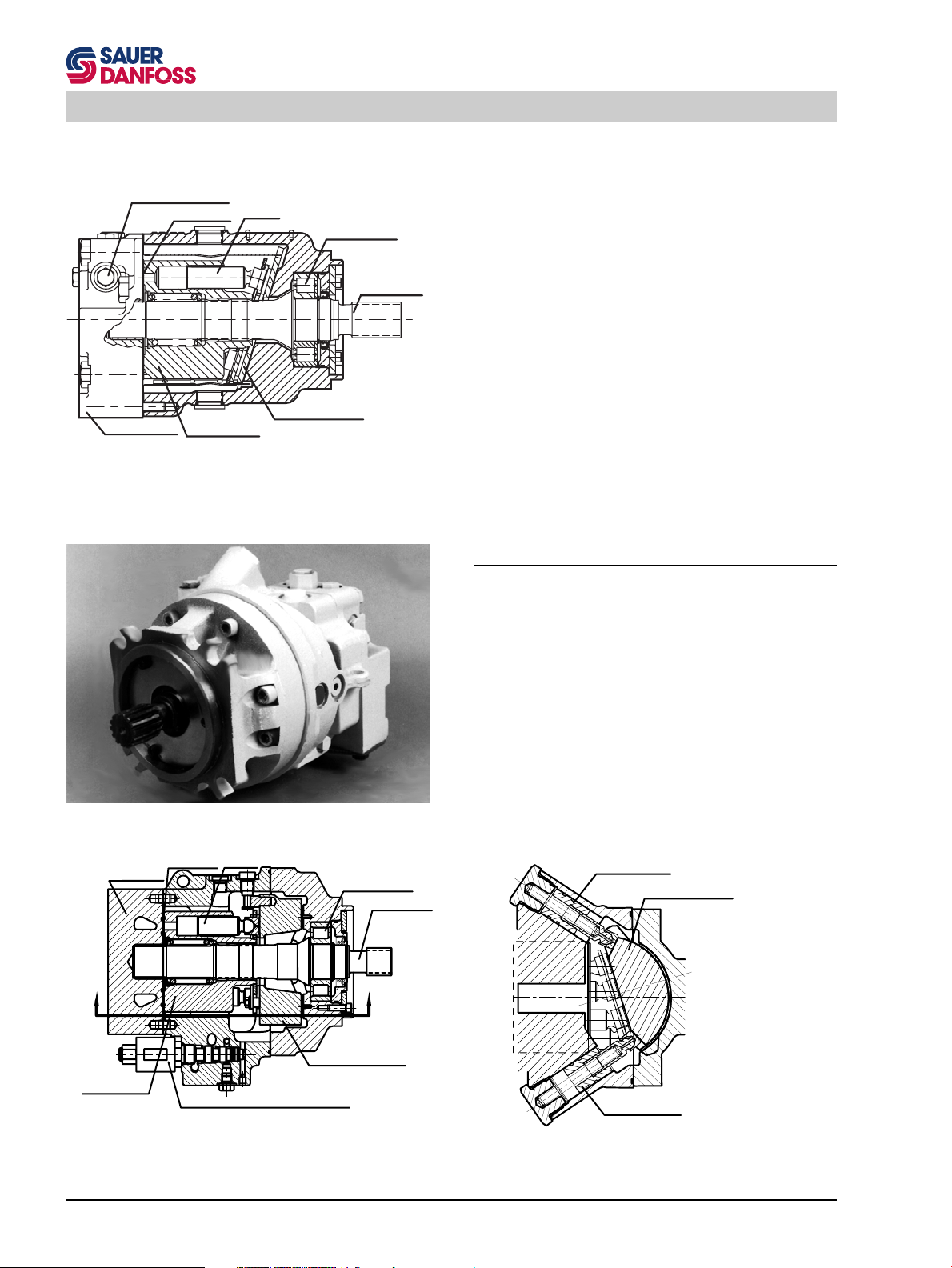
Variable Displacement Pumps
The Variable Displacement Pump (PV) is designed to
convert an input torque into hydraulic power. The input
shaft turns the pump cylinder which contains a ring of
pistons. The pistons run against a tilted plate, called the
swashplate. This causes the pistons to compress the
hydraulic fluid which imparts the input energy into the
hydraulic fluid. The high pressure fluid is then ported out
to provide power to a remote function.
The swashplate angle can be varied by the control piston.
Altering the swashplate angle varies the displacement of
fluid in a given revolution of the input shaft.
Series 90 Variable Displacement Pump (PV)
Slider Block
Cradle Hold Down
Servo Arm
Servo Piston
Servo Valve
F000 539
Feed Back
Cradle Bearing
Fixed Displacement Motor
The Fixed Displacement Motor (MF) is designed to
convert an input of hydraulic power into an output torque.
It operates in the reverse manner of the pump. The high
pressure hydraulic fluid enters through the input port. The
fluid pressure builds behind the pistons causing them to
move down the swashplate (the path of least resistance).
As the piston returns up the swashplate again, the fluid is
allowed to exit through the exit port. The spinning pistons
are housed in a cylinder which is connected to the output
shaft. The output torque can be applied to a mechanical
function.
Charge Pump
Cradle Leveler
Cradle
Cradle Guide
Series 90 PV Cross Section
Series 90 Fixed Displacement Motor (MF)
P001 413E
90000347
5
Page 6
Series 90 Functional Description
In the Fixed Displacement Motor the "swashplate" is
Loop Flushing Valve
Valve Plate
Piston
Roller Bearing
Output Shaft
fixed, so any variation in motor speed and torque must be
made by the input mechanism, i.e. the pump.
End Cap
Cylinder Block
Fixed Swashplate
Series 90 MF Cross Section
Series 90 Variable Displacement Motor (MV)
End Cap
Valve Plate
Piston
Roller Bearing
90000190E
90000348
Output Shaft
Variable Displacement Motor
The Variable Displacement Motor (MV) operates in the
same manner as the fixed motor. However, its swashplate
is not fixed; it can be switched between minimum and
maximum angle to amplify torque or speed like the
Variable Displacement Pump.
Minimum Angle
Control Piston
Cradle Swashplate
"A"
Cylinder Block
6
Cradle Swashplate
Electric 2-Position Control (optional)
"A"
Series 90 MV Cross Section
Maximum Angle
Control Piston
Partial Section "A-A"
Cradle Swashplate in Full
Displacement Position
90000234E
Page 7
Series 90 Functional Description
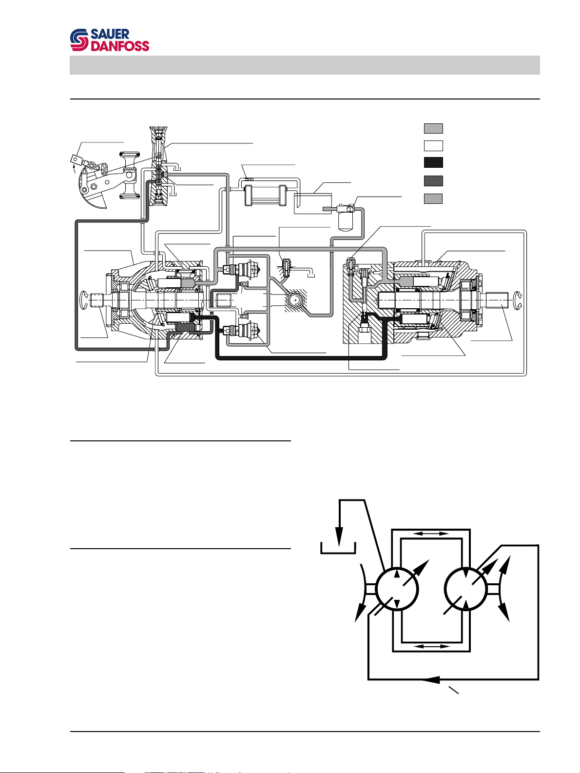
The System Circuit
Control Handle
Variable
Displacement
Pump
Input
Shaft
Pump Swashplate
Displacement Control Valve
Heat Exchanger
Bypass Valve
to Pump
Case
Reservoir
Vacuum Gauge
Purge Relief Valve
Motor Swashplate
Loop Flushing Valve
Orificed
Check Valve
Servo Control
Cylinder
Servo Control
Cylinder
Heat Exchanger
Multi-Function
Valve
Servo Pres.
Relief Valve
Charge Pressure
Relief Valve
Charge Pump
Multi-Function Valve
Pump Fixed Motor
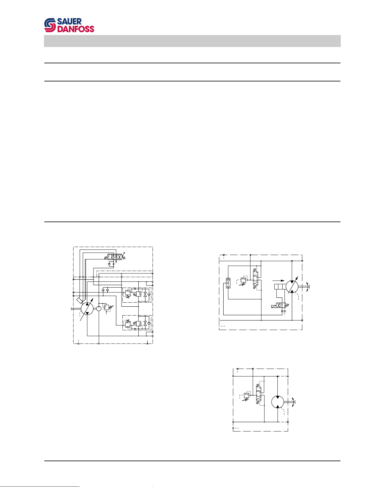
Circuit Diagram for Series 90 PV and 90 MF
System loop
Case drain fluid
System loop
Control fluid
Suction line
Fixed Displacement
Motor
Output Shaft
(low pressure)
(high pressure)
90000800E
The Basic Closed Circuit
The main ports of the pump are connected by hydraulic
lines to the main ports of the motor. Fluid flows, in either
direction, from the pump to the motor then back to the
pump in this closed circuit. Either of the hydraulic lines
can be under high pressure. In pumping mode the
position of the pump swashplate determines which line is
high pressure as well as the direction of fluid flow.
Case Drain and Heat Exchanger
The pump and motor require case drain lines to remove
hot fluid from the system. The motor should be drained
from its topmost drain port to ensure the case remains full
of fluid. The motor case drain can then be connected to
the lower drain port on the pump housing and out the top
most port. A heat exchanger, with a bypass valve, is
required to cool the case drain fluid before it returns to the
reservoir.
Reservoir
Input
PV
Flow (Bi-directional)
Basic Closed Circuit
MF
Output
Case Drain Line
90000803E
7
Page 8
Series 90 Functional Description
Common Features of Pumps and Motors
End Caps and Shafts
Series 90 pumps and motors can be supplied with a
variety of end caps and shafts to allow for almost any
configuration. For pumps, end caps are available with
system ports on either side ("side ports") or both ports on
one side ("twin ports"). Motors have end caps with ports
on the face of the end cap ("axial ports") or both ports on
one side ("twin ports"). See the Series 90 Technical
Information manuals (BLN-10029 and BLN-10030) or the
Series 90 Price Book (BLN-2-40588) for information on
available options.
Removing the end cap will void the warranty on a
Series 90 pump or motor.
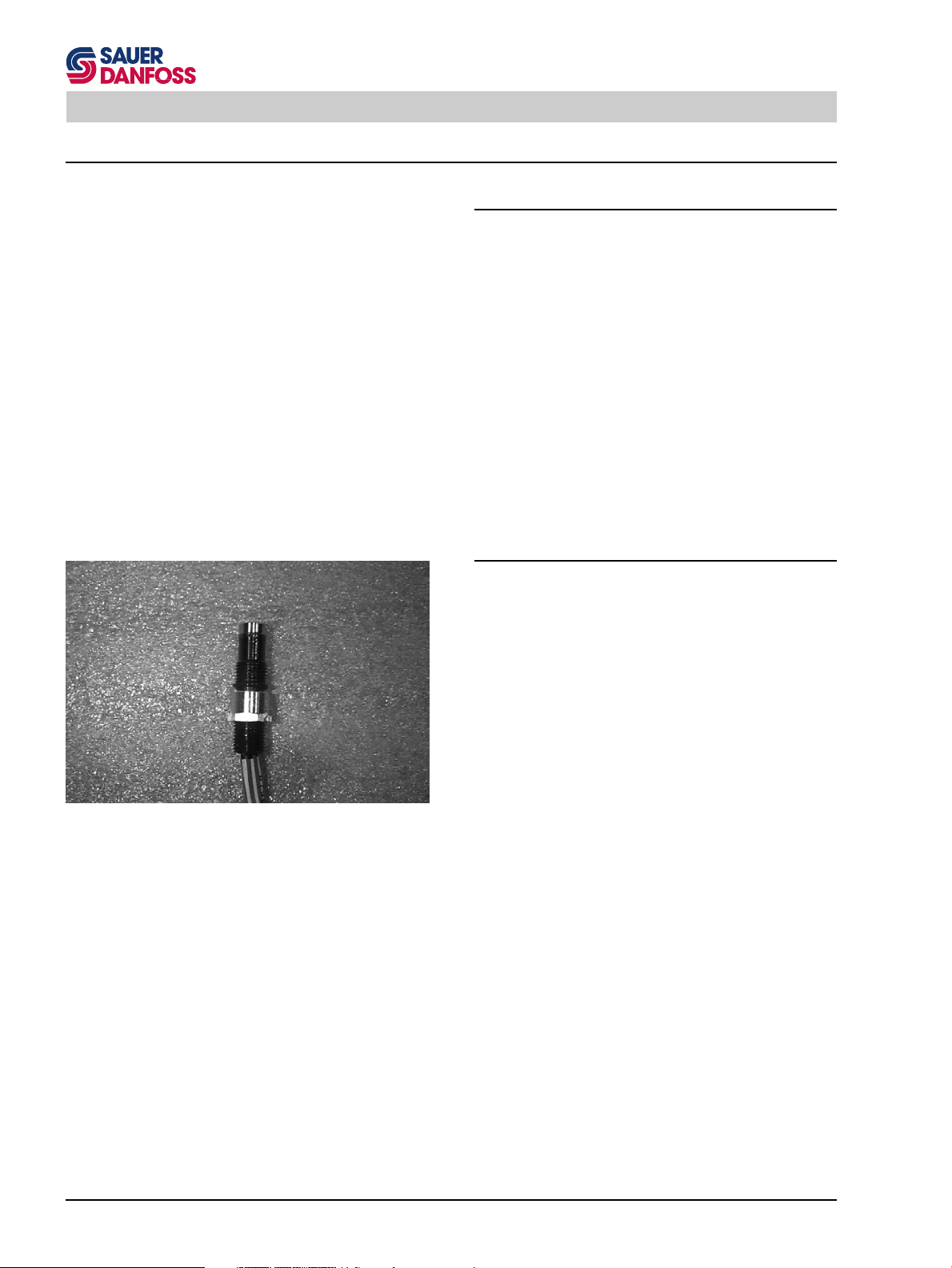
Speed Sensors
Speed Sensor
An optional speed sensor can be installed on Series 90
pumps and motors to provide unit speed information. The
sensor reads a magnetic ring wrapped about the unit's
cylinder. See the corresponding Section to locate, install
and adjust the sensor.
90000810
8
Page 9
Series 90 Functional Description
Pump Features
Charge Pump
The charge pump is necessary to supply cool fluid to the
system, to maintain positive pressure in the main system
loop, to provide pressure to operate the control system,
and to make up for internal leakage. Charge pressure
must be at its specified pressure under all conditions of
driving and braking to prevent damage to the transmission.
The charge pump is a fixed-displacement, gerotor type
pump installed in the variable displacement pump and
driven off the main pump shaft. Charge pressure is limited
by a relief valve.
The standard charge pump will be satisfactory for most
applications. However, if the charge pump sizes available
for the given main pump size are not adequate, a gear
pump may be mounted to the auxiliary mounting pad and
supply the required additional charge flow.
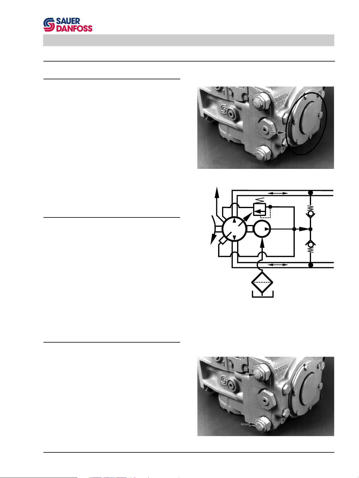
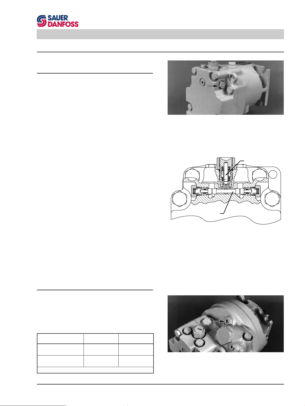
Charge Relief Valve
The charge relief valve on the pump serves to maintain
charge pressure at a designated level. A direct-acting
poppet valve relieves charge pressure whenever it surpasses a certain level. This level is nominally set referencing case pressure at 1500 rpm. This nominal setting
assumes the pump is in neutral (zero flow); in forward or
reverse charge pressure will be lower. The charge relief
valve setting is specified on the model code of the pump.
Multi-Function Valves
Case
Drain
Input
Line
90000243
PV with Charge Pump
Charge Relief Valve
System
Check
Valves
PV PF
Charge
Pump
Inlet Filter
Tank
90000804E
Pump Charge System
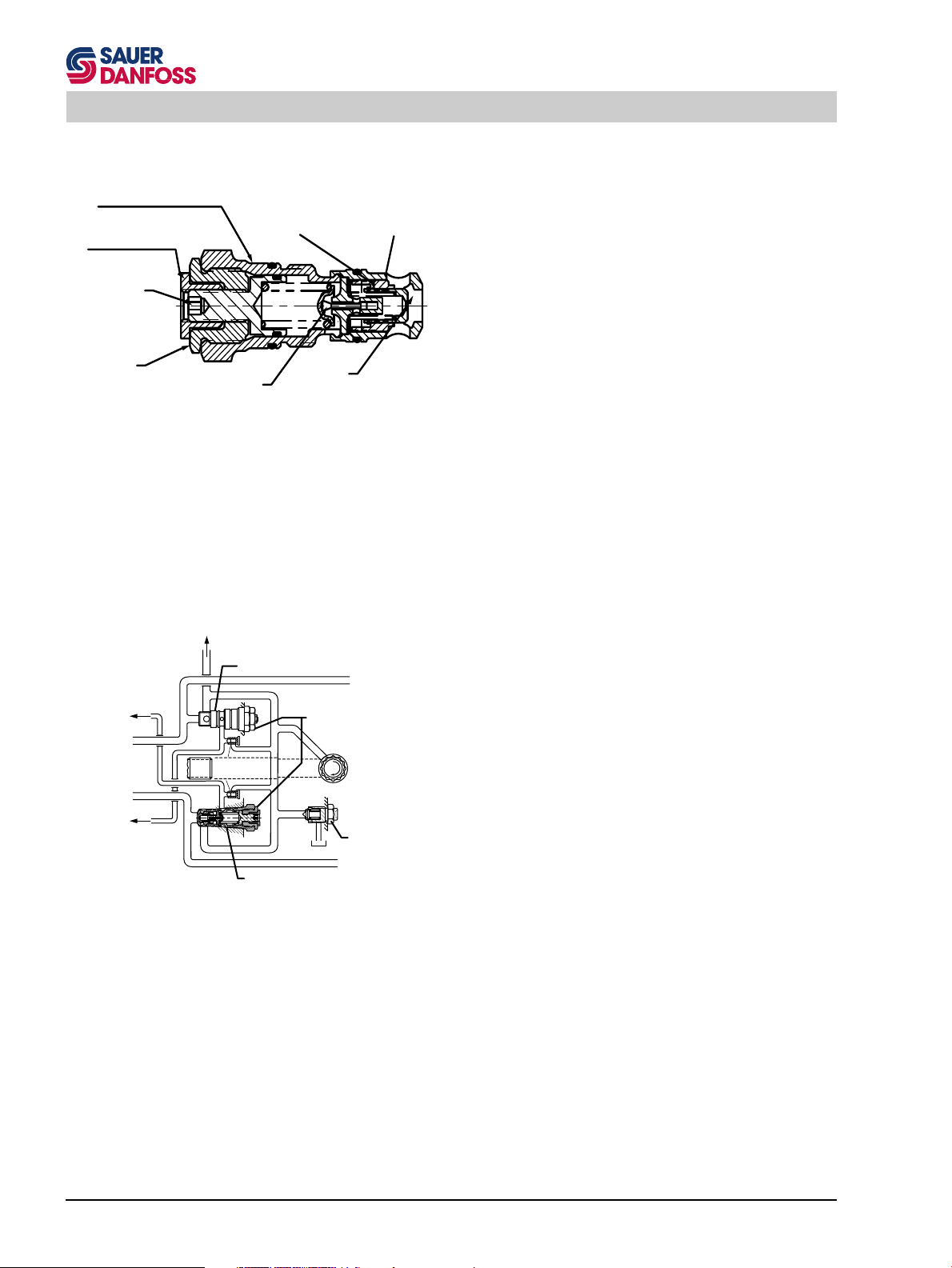
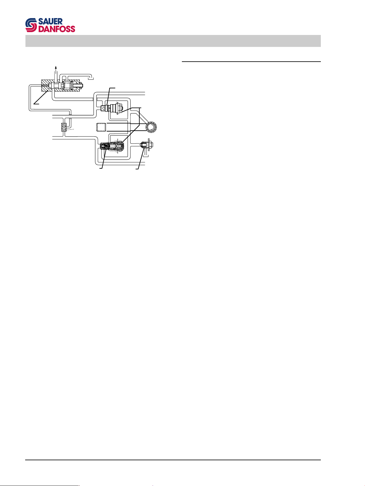
The multi-function valve incorporates
the system check valve,
the pressure limiter valve,
the high pressure relief valve and
the bypass valve
in a replaceable cartridge.
These functions are described separately. There are two
multi-function valve cartridges in each Series 90 pump to
handle functions in either direction. See corresponding
Sections for adjustments and repairs.
NOTE: Some multi-function valves do not include a
pressure limiter valve.
90000243
Multi-Function Valve
9
Page 10
Series 90 Functional Description
Pressure Limiter and High Pressure Relief Valves
Pressure Limiter Housing
Pressure Limiter
Lock Nut
Pressure Limiter
Adjustment Screw
Bypass
Actuator
Cross Section of Multi-Function Valve
Servo Piston
Port "A"
Port "B"
Servo Piston
Pressure Limiter
Valve Poppet
To Control
Multi-Function Valve
Servo Pres.
Relief Valve
High Pressure
Relief / check
Valve Poppet
Bypass
Bypass
Adjustment
Check Valve
Poppet
90000806E
Charge Pressure
Relief Valve
Series 90 pumps are designed with a sequenced pressure limiting system and high pressure relief valves.
When the preset pressure is reached, the pressure limiter
system acts to rapidly destroke the pump so as to limit the
system pressure. For unusually rapid load application,
the high pressure relief valve acts to immediately limit
system pressure by cross-porting system flow to the low
pressure side of the loop. The pressure limiter valve acts
as the pilot for the high pressure relief valve spool. The
high pressure relief valve is sequenced to operate at
approximately 35 bar (500 psi) above the level that initiates the pressure limiter valve.
Both the pressure limiter sensing valves and relief valves
are built into the multi-function valves (see above).
NOTE: For some applications, such as dual path ve-
hicles, the pressure limiter function may be defeated so that only the high pressure relief valve
function remains.
System Check Valves
The system check valves allow pressurized flow from the
charge pump to enter the low pressure side of the loop
whenever system pressure dips below a certain level.
This is needed as the pump will generally lose system
pressure due to leakage and other factors. Since the
pump can operate in either direction, two system check
valves are used to direct the charge supply into the low
pressure lines. The system check valves are poppet
valves located in the multi-function valve assembly.
Bypass Valves
The bypass valves ("tow") can be operated when it is
desired to move the vehicle or mechanical function when
the pump is not running. The valve is opened by manually
resetting the valve position.
10
Multi-Function Valve
Circuit Diagram showing Pressure
Control Mechanism
90000801E
The bypass valves are built into the multi-function valves.
Page 11
Series 90 Functional Description
Displacement Limiters
All Series 90 pumps are designed for optional mechanical
displacement (stroke) limiters. The maximum displacement of the pump can be limited in either direction.
The setting can be set as low as 0° in either direction.
For instructions on adjustment see corresponding Section.
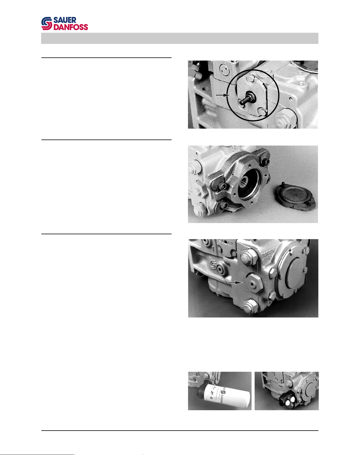
Auxiliary Mounting Pads
Auxiliary mounting pads are available on all Series 90
pumps. SAE A through E mounts are available (availability varies by pump size). This pad is used for mounting
auxiliary hydraulic pumps and for mounting additional
Series 90 pumps to make tandem pumps. The pads allow
for full through-torque capability.
Filtration Options
All Series 90 pumps are available with provisions for
either suction or charge pressure filtration (integral or
remote mounted) to filter the fluid entering the charge
circuit.
Suction Filtration
The suction filter is placed in the circuit between the
reservoir and the inlet to the charge pump. When suction
filtration is used, a reducer fitting is placed in the charge
pressure gauge port (M3). Filtration devices of this type
are provided by the user.
Charge Pressure Filtration
90000244
PV with Displacement Limiters
90000242
PV with Auxillary Mounting Pad
90000243
PV with Suction Filtration
(No filtration device attached)
The pressure filter may be integrally mounted directly on
the pump or a filter may be remotely mounted for ease of
servicing.
A 125 µm screen, located in the reservoir or the charge
inlet line, is recommended when using this filtration
option.
PV with Integral Charge
90000246
Pump
PV with Remote Charge
90000247
Pump
11
Page 12
Series 90 Functional Description
To Control
Pressure
Override Control Valve
Port "A"
Shuttle
Valve
Port "B"
Multi-Function Valve
POR-Valve (180 Frame Size only)
Multi-Function Valve
Charge Pressure
Relief Valve
Bypass
Adjustment
90000802E
Pressure Override (POR) - 180 Frame Size Only
The pressure override valve (POR) modulates the control
pressure to the displacement control to maintain a pump
displacement which will produce a system pressure level
less than or equal to the POR setting. For unusually rapid
load application, the high pressure relief valve function of
the multifunction valves is available to also limit the
pressure level.
The pressure override consists of a three-way normally
open valve which operates in series with the pump
displacement control. Control supply pressure is normally ported through the pressure override valve to the
displacement control valve for controlling the pump's
displacement. If the system demands a pressure above
the override setting, the POR valve will override the
control by reducing the control pressure supplied to the
displacement control. As the control pressure reduces,
the internal forces tending to rotate the swashplate
overcome the force of the servo pistons and allow the
pump's displacement to decrease.
12
Page 13
Series 90 Functional Description
Pump Control Options
Manual Displacement Control (MDC)
The manual displacement control converts a mechanical input signal to a hydraulic signal using a spring- centered fourway servo valve. This valve ports hydraulic pressure to either side of a dual-acting servo piston. The servo piston rotates
the cradle swashplate through an angular rotation of ±17°, thus varying the pump’s displacement from full displacement
in one direction to full displacement in the opposite direction.
The MDC is designed so the angular position of the pump swashplate is proportional to the rotation of the control input
shaft.
Non-Linear MDC
The non-linear manual displacement control operates in
the same manner as the regular MDC except that it is
designed so the change in the angular position of the
pump swashplate
input shaft is rotated toward its maximum displacement
position.
Solenoid Override Valve for MDC
progressively
increases as the control
A solenoid override valve option (not shown here) is
available for MDC. This safety feature will return the
swashplate to zero displacement position when activated. The valve may be set in either a normally open or
normally closed mode.
Neutral Start Switch (NSS)
The neutral start switch is an optional feature available
with MDC. When connected properly with the vehicle’s
electrical system, the neutral start switch ensures that the
prime mover can be started only when the control is in a
neutral position.
Hydraulic Displacement Control (HDC)
The hydraulic displacement control uses a hydraulic input
signal to operate a spring-centered four-way servo valve.
This valve ports hydraulic pressure to either side of a
dual-acting servo piston. The servo piston rotates the
cradle swashplate through an angular rotation of ±17°,
thus varying the pump’s displacement from full displacement in one direction to full displacement in the opposite
direction. The HDC is designed so the angular position of
the pump swashplate is proportional to input pressure.
90000237
PV with Manual Displacement Control
90000239
PV with Manual Displacement Control and
Neutral Start Switch
PV with Hydraulic Displacement Control
90000240
13
Page 14
Series 90 Functional Description
Electric Displacement Control (EDC)
The electric displacement control is similar to the hydraulic displacement control with the input signal pressure
controlled by a pressure control pilot (PCP) valve. The
PCP valve converts a DC electrical input signal to a
hydraulic signal which operates a spring- centered fourway servo valve. This valve ports hydraulic pressure to
either side of a dual-acting servo piston. The servo piston
rotates the cradle swashplate through an angular rotation
of ±17°, thus varying the pump’s displacement from full
displacement in one direction to full displacement in the
90000241
PV with Electric Displacement Control
opposite direction. The control is designed so the angular
position of the swashplate is proportional to the EDC
input.
Automotive Control (FBA II B)
Automotive Control allows a vehicle to be driven in a
manner similar to an automobile with an automatic transmission.
The Automotive Control includes a three-position electric
control to provide direction control.
PV with 3-Position (FNR) Electric Control
3-Position (FNR) Electric Control
This control utilizes a 12 or 24 VDC electrically operated
spool valve to port pressure to either side of the pump
displacement control piston. Energizing one of the solenoids will cause the pump to go to its maximum displacement in the corresponding direction.
All functions of the three-position (FNR) electric control
are preset at the factory.
90000354
14
Page 15
Series 90 Functional Description
Charge Relief Valve
Loop Flushing Shuttle Valve
End Cap
Top of Motor
Motor Features
Motor Loop Flushing Valve and Charge Relief
Valve
All Series 90 motors are designed to accommodate a loop
flushing valve. The loop flushing valve is used in installations which require additional fluid to be removed from
the main hydraulic circuit because of transmission cooling requirements, or unusual circuits requiring additional
loop flushing to remove excessive contamination in the
high pressure circuit.
Loop Flushing Valve (MF)
A shuttle valve and charge relief valve are installed in the
motor end cap to provide the loop flushing function. The
shuttle valve provides a circuit between the low pressure
side of the closed loop and the charge relief valve in the
motor end cap.
The motor charge relief valve regulates the charge pressure level only when there is a pressure differential in the
main loop. The shuttle valve is spring centered to the
closed position so that no high pressure fluid is lost from
the circuit when reversing pressures.
90000248
For charge relief valve adjustment see corresponding
Section.
Variable Motor Displacement Limiters
All Series 90 variable motors include mechanical displacement (stroke) limiters. Both the maximum and minimum displacement of the motor can be limited.
The range of the settings is as follows:
muminiM
tnemecalpsiD
mumixaM
tnemecalpsiD
VM550VM570
3
mc04-91
3
ni4.2-2.1
%001-56%001-56
3
mc45-62
3
ni3.3-6.1
E152200T
90000238E
Motor Charge Relief Valve and Loop Flushing
Shuttle Valve
90000352
MV Maximum Displacement Limiter
(Minimum Displacement Limiters on opposite side)
15
Page 16
Series 90 Functional Description
Variable Motor Controls
Hydraulic 2-Position Control
This control utilizes a hydraulically operated three-way
hydraulic valve to port system pressure to either of the
motor displacement control pistons. The motor is normally held at its maximum displacement. Supplying pilot
hydraulic pressure to the valve will cause the motor to go
to its minimum displacement.
90000350
MV with Hydraulic 2-Position Control
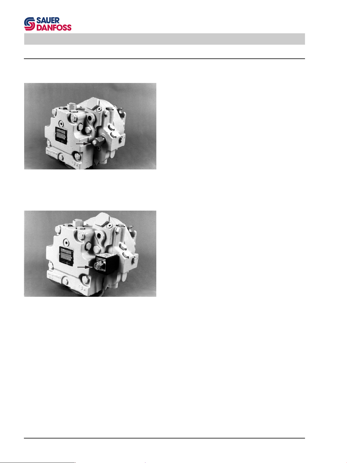
Electric 2-Position Control
This control utilizes an electric solenoid operated threeway hydraulic valve to port system pressure to either of
the motor displacement control pistons. The motor is
normally held at its maximum displacement. Energizing
the solenoid will cause the motor to go to its minimum
displacement.
16
90000351
MV with Electric 2-Position Control
Page 17
Series 90 Technical Specifications
M2
B
L1
M1
A
L2
M3
Technical Specifications
General Specifications
Design
Variable Pumps and Motors: Axial piston pump of variable displacement, cradle swashplate design.
Fixed Motors: Axial piston motor with fixed displacement,
fixed swashplate design.
Type of Mounting (per SAE J744)
SAE flange, Size "B", 2 bolts,
SAE flange, Size "C and E", 4 bolts.
Cartridge flange, 2 bolts (for motor only).
Circuit Diagrams
Port Connections
(for details see chapter "Pressure Measurement")
Main pressure ports: SAE flange, Code 62,
Remaining ports: SAE straight thread O-ring boss.
Direction of Rotation
Clockwise or counterclockwise (motors are bi-directional)
Recommended Installation Position
Pump installation recommended with control position on
the top or side. Consult SAUER-SUNDSTRAND for nonconformance guidelines. The housing must always be
filled with hydraulic fluid.
L2
A
M3
M1
M5
M4
M3
X5
L1
S
A
M1
B
M2
B
L2
L1
MV with Electrohydraulic 2-Position
Control
Vg
max
M2
PV with Charge Pump and Manual
Displacement Control
MF
90000811
90000812
90000813
17
Page 18
Series 90 Technical Specifications
Hydraulic Parameters
)1
egnaRerusserPmetsySrabisp
erusserPdetaR0240006
erusserPmumixaM0840696
muminiM04-]04-[tratsdloc,tnettimretni
detaR401]022[
mumixaM511]042[tnettimretni
E252200T
)1
C°]F°[
.tropniard
egnaRerutarepmeT
esacehtyllamron,tnioptsettohehttA
E600200T
muucaVtelnIpmuPegrahC
)ylnospmupno(
muucaVmuminiM
)suounitnoc(
sbarabgHni
7.001
gnirudmuucaVmuminiM
tratSdloC
2.052
)tnettimretnI(
erusserPesaCrabisp
)suounitnoC(mumixaM344
)tnettimretnI(
tratSdloCgnirudmumixaM
537
Hydraulic Fluid
Refer to SAUER-SUNDSTRAND BLN 9887 or SDF (Id
No. 697581). Also refer to publication ATI-E 9101 for
information relating to biogradable fluids.
ytisocsiV
egnargnitarepo
x
noitartlifnoitcusrof
x
erusserpegrahcrof
telnidednemmoceR
noitartliferusserp
mm2s/]SUS[
06-21]872-07[
ssenilnaelcdiulfderiuqeR
oitar-
oitar-
egrahcrofezisneercs
dnaleveLssenilnaelC βββββ
x
β
54-53
β
02-51
001 µ 521-m µm
,tnettimretni
tratsdloc
E010200T
oitaR-
31/81ssalC6044OSI
(57= β01≥ )2
(57= β01≥ )01
E700200T
muminiM7]94[tnettimretni
dednemmoceR
mumixaM0061]0057[
E352200T
level
dednemmoceR β
dednemmoceR β
noitartlif
E452200T
Cleanliness
Refer to SAUER-SUNDSTRAND Publications BLN 9887
or SDF (NO. 697581) and ATI-E 9201.
Refer to Series 90 technical information for definitions.
18
Page 19
Series 90 Technical Specifications
Size Specific Data
Variable Displacement Pumps
noisnemiDVP030VP240VP550VP570VP001VP031VP081VP052
tnemecalpsiD
)mumixam(
deepSmuminiMnim
deepSdetaRnim
deepSmumixaMnim
deepSelbaniattamumixaM
tnemecalpsiD.xamta
taeuqroTlaciteroehT
tnemecalpsiD.xam
thgieW
)tinuesabylno(
Fixed and Variable Displacement Motors
3
mc
3
ni
1-
)mpr(005005005005005005005005
1-
)mpr(00240024009300630033001300620032
1-
)mpr(00640064052405930563004305820052
1-
nim
)mpr(00050005007400340004007305130572
rab/mN
gk
bl
03
38.1
84.0
isp0001/ni•fbl
092
82
26
24
65.2
76.0
083
43
57
55
53.3
88.0
035
04
88
57
75.4
91.1
037
94
801
001
01.6
95.1
078
86
051
031
39.7
70.2
0621
88
591
081
89.01
78.2
0571
631
003
052
52.51
79.3
3342
451
043
E752200T
tiehniEFM030FM240FM550FM570FM001FM031VM550VM570
3
)mumixam(tnemecalpsiD
)muminim(tnemecalpsiD
mumixamta
detaR
deeps
tnemecalpsid
muminimta
tnemecalpsid
mumixamta
mumixaM
deeps
tnemecalpsid
muminimta
tnemecalpsid
tadeepselbaniatta.xaM
tnemecalpsid.xam
.xamtaeuqrotlaciteroehT
mc
3
ni
3
mc
3
ni
1-
nim
)mpr(00240024009300630033001300930063
1-
nim
)mpr(------------00640524
1-
)mpr(00640064052405930563004305240593
nim
1-
nim
)mpr(------------00150074
1-
nim
)mpr(00050005007400340004007300740034
rab/mN
tnemecalpsid
tnemecalpsid
.xamrawolfmumixaM
rewoprenroc.xaM
thgieW
egnalF-EAS
thgieW
rotoMegdirtraC
nim/l
nim/lag
Wk
ph
gk
bl
gk
bl
03
38.1
24
65.2
55
53.3
57
75.4
001
01.6
031
39.7
------------9162
isp0001/ni•fbl
092
831
5.63
111
941
11
42
--
84.0
76.0
083
391
15
551
802
51
43
12
64
88.0
035
432
26
781
152
22
94
62
75
91.1
037
692
87
732
813
62
75
33
27
95.1
079
563
69
292
293
43
47
----
70.2
0621
244
711
453
574
54
99
55
53.3
88.0
035
432
26
422
003
93
68
04
88
57
75.4
91.1
037
692
87
282
873
44
89
64
101
E852200T
Refer to Series 90 technical information for definitions.
19
Page 20
Series 90 Pressure Measurement
Pressure Measurement
Required Tools
The service procedures described in this manual for
Series 90 pumps and motors can be performed using
common mechanic's tools. Special tools, if required are
shown.
Port Locations and Pressure Gauge Installation
The following sections list the ports for each type of
hydraulic unit. The recommended pressure gauge and
fitting are also specified.
Variable Pump
troPnoitcnuF
1M
2M
3M
)6M(
4M
5M
erusserPmetsyS
"A"troP
erusserPmetsyS
"B"troP
erusserPegrahC
erusserPovreS
eziSeguaG
dna
gnittiF
isp00001rorab0001
gnir-O81-61/9
isp00001rorab0001
gnittifgnir-O81-61/9
isp0001rorab05
gnir-O81-61/9
isp0001rorab05
gnir-O81-61/9
E952200T
Pressure gauges should be calibrated frequently to ensure accuracy. Snubbers are recommended to protect
pressure gauges.
Outline drawings showing port locations follow the tables
below.
eziSeguaG
troPnoitcnuF
dna
gnittiF
1L
2L
1X
2X
3X
S
erusserPesaC
030
240
550
570
001
031gnir-O21-61/5-1
081
052
CDE/CDH
erusserPlortnoC
lortnoClanretxE
erusserP
telnIpmuPegrahC
030
240
550
570
001
031
081
052
isp001rorab01
gnir-O41-8/7
gnir-O21-61/1-1
gnir-O21-8/5-1
isp0001rorab05
gnir-O02-61/7
ro
gnir-O81-61/9
isp0001rorab05
gnir-O81-61/9
otnieeT,eguaGmuucaV
eniLtelnI
gnir-O21-61/1-1
gnir-O21-61/5-1
gnir-O21-8/5-1
tilpS-EAS2/1-1
egnalF
E062200T
20
Page 21
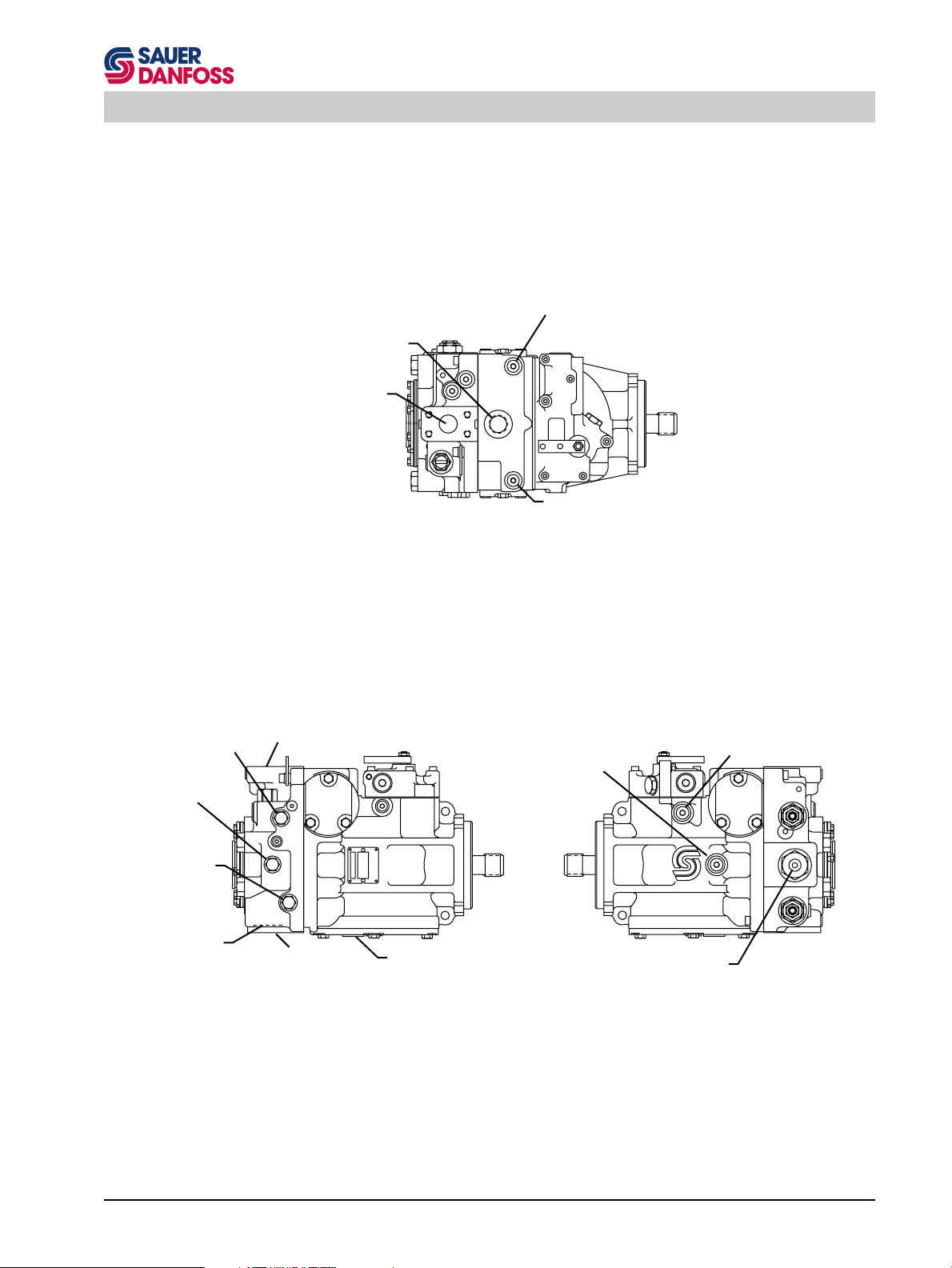
Series 90 Pressure Measurement
Servo / Displacement
Cylinder Pressure
Gauge Port M4
Case Drain
Port L1
System Pressure
Port B
Servo / Displacement
Cylinder Pressure
Gauge Port M5
Top View
System Pressure
Gauge Port M2
Charge Inlet Pressure
System Pressure
Gauge Port M1
Carge Pump
Inlet Port S
System Pressure
Port B
System Pressure
Port A
Left Side View
Case Drain Port L2
90000814E
External Control Pressure
Supply Port X3
Speed Sensor
Charge Pressure
Gauge Port M3
Right Side View
PV with Side Port End Cap and Manual Displacement Control
90000815E
90000816E
21
Page 22
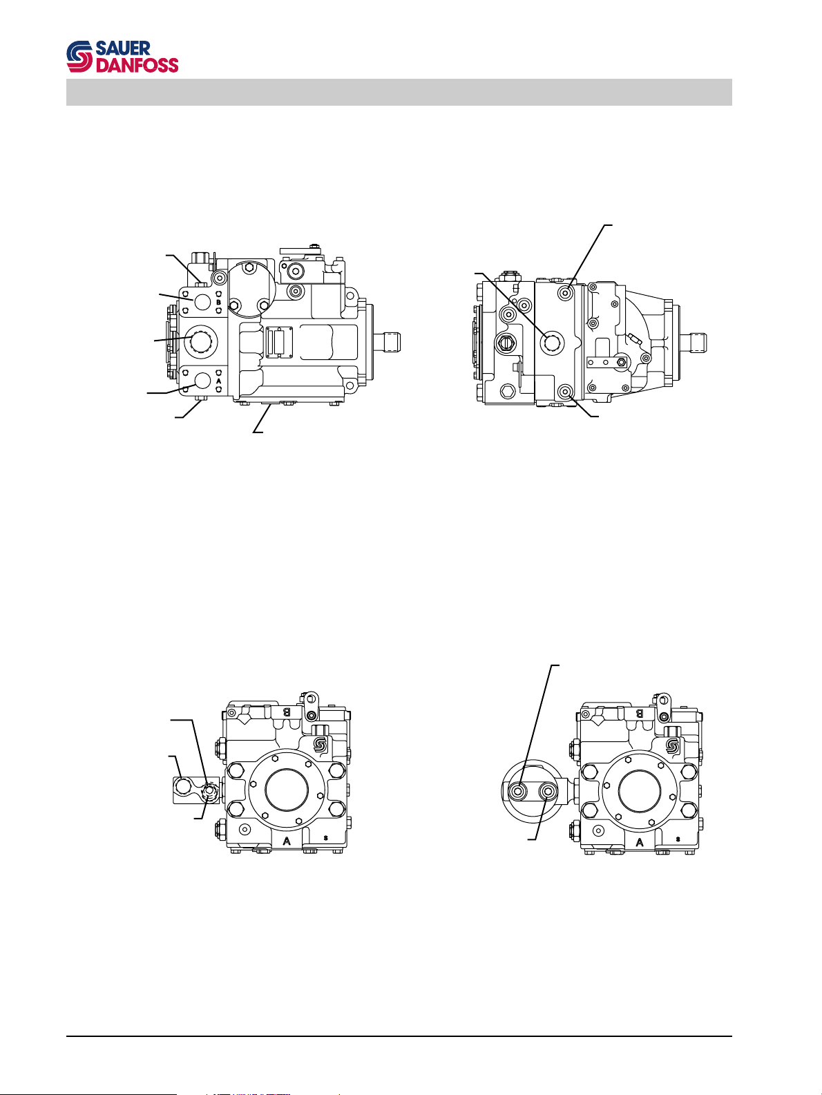
Series 90 Pressure Measurement
Servo / Displacement
Cylinder Pressure
System Pressure
Gauge Port M2
System Pressure
Port B
Charge Pump Inlet
Port S
System Pressure
Port A
System Pressure
Gauge Port M1
Case Drain
Port L1
Case Drain Port L2
Top View
Left Side View
Gauge Port M4
Servo / Displacement
Cylinder Pressure
Gauge Port M5
Port E
(from filter)
Port D
(to filter)
Charge Pressure
Gauge Port M3
(after the filter)
PV with Twin Port End Cap and Manual Displacement Control
Charge Pressure
Gauge Port M3
Rear View
(after the filter)
Charge Pressure
Gauge Port M6
(before the filter)
Rear View
90000819E
90000820E
90000817E
90000818E
PV with Side Port End Cap and Remote Pressure Filtration PV with Side Port End Cap and Integral Pressure Filtration
22
Page 23
Series 90 Pressure Measurement
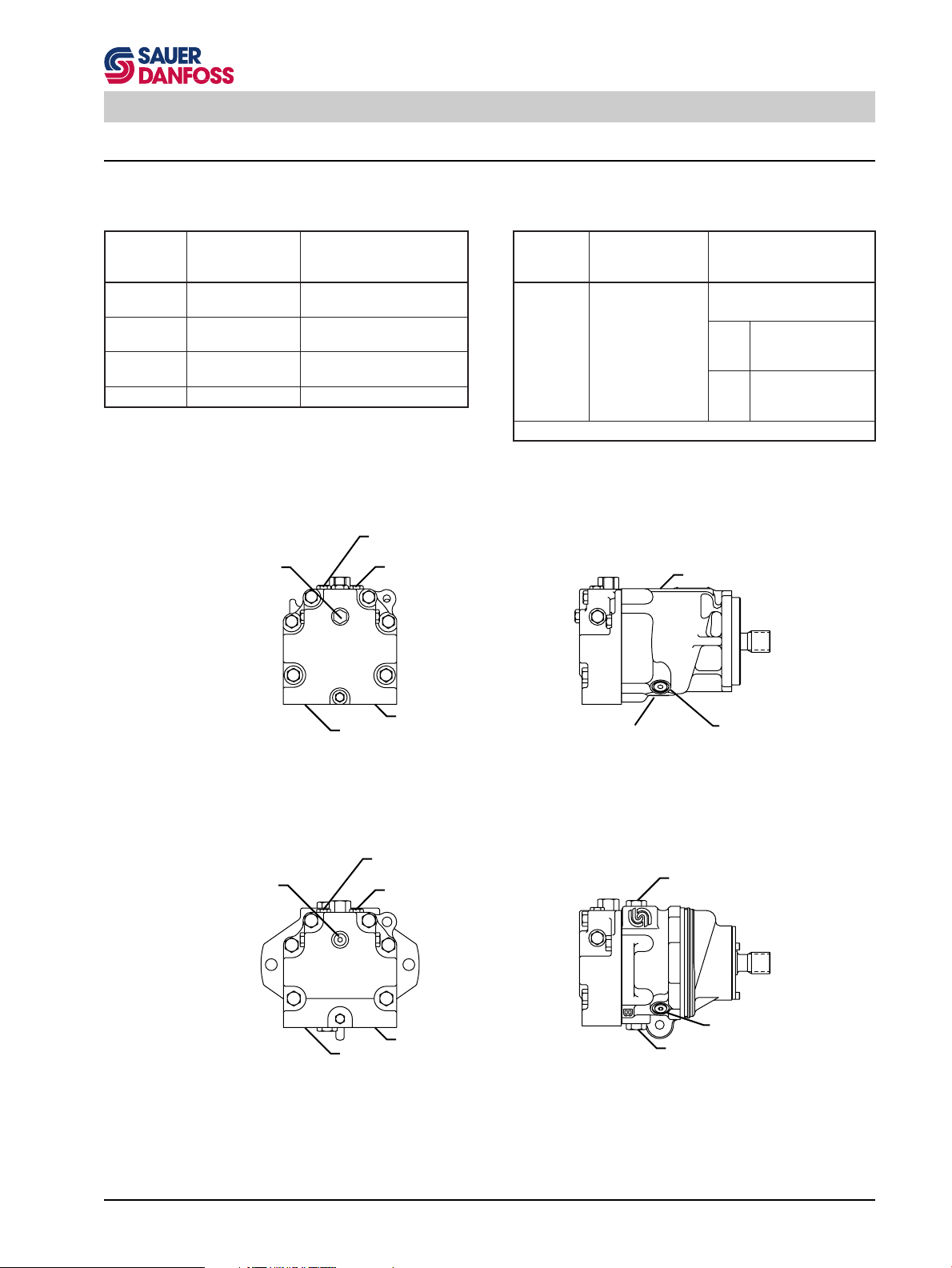
Fixed Motor
troPnoitcnuF
1M
2M
3M
Charge Pressure
Gauge Port M3
eziSeguaG
dna
gnittiF
erusserPmetsyS
"A"troP
erusserPmetsyS
"B"troP
erusserPegrahC
System Pressure
Gauge Port M1
System Pressure
Gauge Port M2
isp00001rorab0001
gnir-O81-61/9
isp00001rorab0001
gnir-O81-61/9
isp0001rorab05
gnir-O81-61/9
E162200T
troPnoitcnuF
1L
2L
)erusserPesaC
030
240
550
570
001
031
Case Drain Port L1
eziSeguaG
dna
gnittiF
isp005rorab01
gnir-O41-8/7
gnir-O21-61/1-1
E262200T
Charge Pressure
Gauge Port M3
System Pressure Port A
Rear View
System Pressure
Gauge Port M1
System Pressure
Gauge Port M2
System Pressure Port A
Rear View
System Pressure Port B
MF with SAE Flange
System Pressure Port B
MF with Cartridge Flange
Case Drain Port L2
Left Side View
Left Side View
Speed Sensor
Case Drain Port L1
Speed Sensor
Case Drain Port L2
90000821E
23
Page 24
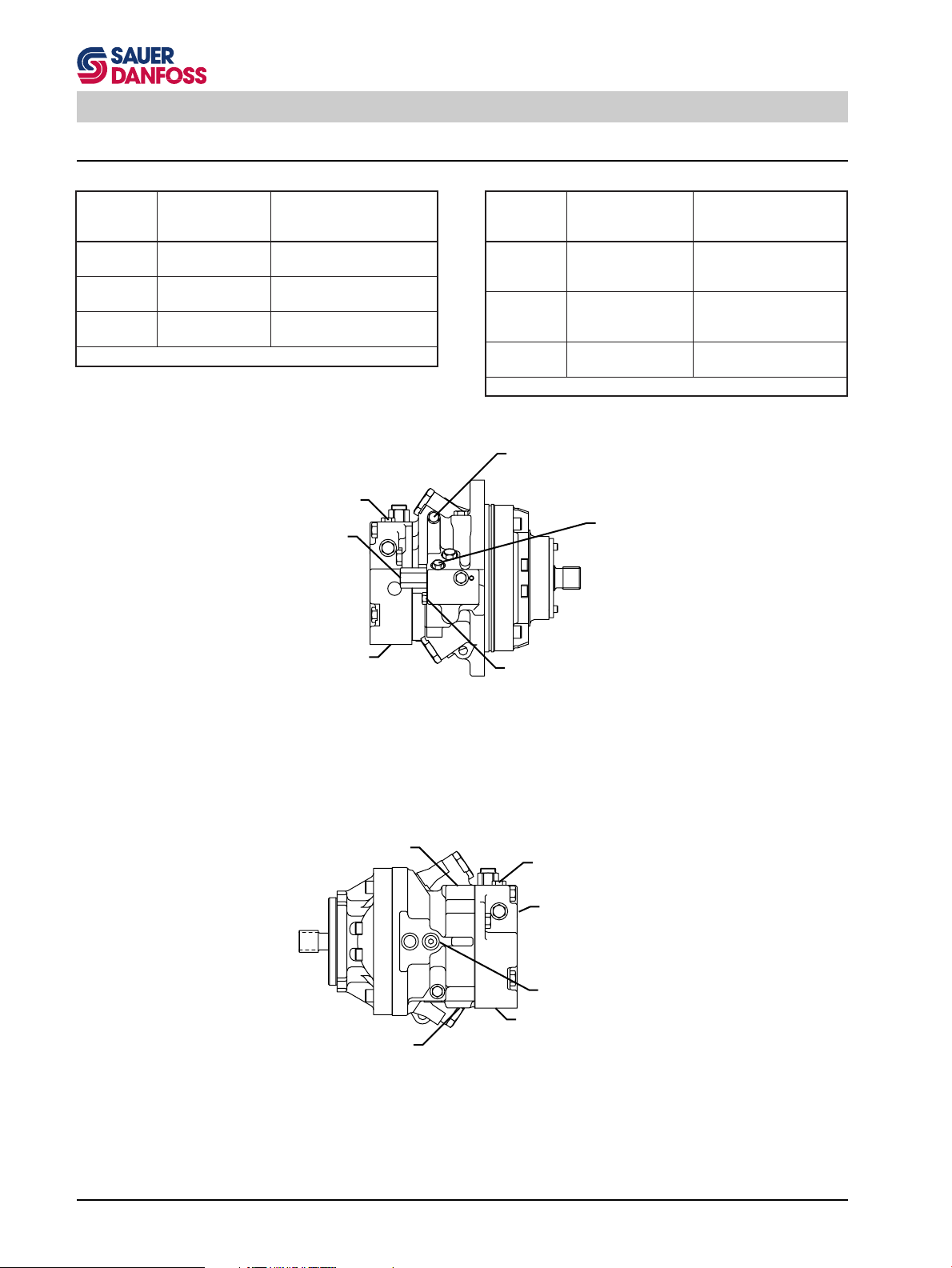
Series 90 Pressure Measurement
Variable Motor
troPnoitcnuF
1M
2M
3M
(Hydraulic 2-Position Control)
erusserpmetsyS
"A"troP
erusserpmetsyS
"B"troP
erusserPegrahC
System Pressure
Gauge Port M2
Control Pressure
Port X1
System Pressure Port B
eziSeguaG
dna
gnittiF
gnir-O81-61/9
gnir-O81-61/9
gnir-O81-61/9
isp00001rorab0001
isp00001rorab0001
isp0001rorab05
E362200T
Left Side View
troPnoitcnuF
4M
5M
1L
2L
Displacement Control
Cylinder Pressure
Gauge Port M4
Min. Displacement
Displacement Control
Cylinder Pressure
Gauge Port M5
Max. Displacement
(Earlier Production Not available as gauge
port with servo orifices)
Displacement Control
Cylinder Pressure
Gauge Port M5
Max. Displacement
(Newer Production)
eziSeguaG
dna
gnittiF
redbnilyClortnoC
muminiM"erusserP
"tnemecalpsiD
redbnilyClortnoC
mumixaM"erusserP
"tnemecalpsiD
erusserPesaC
isp00001rorab0001
gnir-O02-61/7
isp00001rorab0001
gnir-O02-61/7
isp005rorab01
gnir-O21-61/1-1
E462200T
24
MV with Cartridge Flange and Hydraulic 2-Position Control (SAE Flange Version Similar)
Case Drain Port L1
Case Drain Port L2
Right Side View
MV with SAE Flange (Cartridge Flange Version Similar)
System Pressure
Gauge Port M1
charge Pressure
Gauge Port M3
(Same position as in MF)
Speed Sensor
System Pressure Port A
90000823E
Page 25
Series 90 Initial Start-Up Procedure
Initial Start-Up Procedure
The following start-up procedure should always be followed when starting-up a new Series 90 installation or
when restarting an installation in which either the pump or
motor had been removed.
WARNING
The following procedure may require the vehicle/
machine to be disabled (wheels raised off the ground,
work function disconnected, etc.) while performing
the procedure in order to prevent injury to the
technician and bystanders. Take necessary safety
precautions before moving the vehicle/machine.
S000 007E
Prior to installing the pump and/or motor, inspect the units
for damage incurred during shipping and handling. Make
certain all system components (reservoir, hoses, valves,
fittings, heat exchanger, etc.) are clean prior to filling with
fluid.
Fill the reservoir with recommended hydraulic fluid. This
fluid should be passed through a 10 micron (nominal, no
bypass) filter prior to entering the reservoir. The use of
contaminated fluid will cause damage to the components,
which may result in unexpected vehicle/machine movement. See the publications BLN-9887 and SDF 697581
for further related information.
The inlet line leading from the reservoir to the pump must
be filled prior to start-up. Check inlet line for properly
tightened fittings and make sure it is free of restrictions
and air leaks.
Be certain to fill the pump and/or motor housing with
clean hydraulic fluid prior to start up.
Fill the housing by pouring filtered oil into the upper case
drain port.
Install a 50 bar (or 1000 psi) pressure gauge in the charge
pressure gauge port to monitor the charge pressure
during start-up.
It is recommended that the external control input signal
(linkage for MDC, hydraulic lines for HDC, or electrical
connections for EDC) be disconnected at the pump
control until after initial start-up. This will ensure that the
pump remains in its neutral position.
WARNING
Do not start prime mover unless pump is in neutral
position (0° swashplate angle). Take precautions to
prevent machine movement in case pump is actuated
during initial start up.
S000 008E
“Jog” or slowly rotate prime mover until charge pressure
starts to rise. Start the prime mover and run at the lowest
possible RPM until charge pressure has been established. Excess air may be bled from the high pressure
lines through the high pressure system gauge port.
Once charge pressure has been established, increase
speed to normal operating RPM. Charge pressure should
be as indicated in the pump model code. If charge
pressure is inadequate, shut down and determine cause
for improper pressure. Refer to Troubleshooting.
WARNING
Take necessary precautions that the motor shaft
remains stationary during the adjustment
procedure.
S000 010E
Shut down the prime mover and connect the external
control input signal. Also reconnect the machine function
if disconnected earlier. Start the prime mover, checking
to be certain the pump remains in neutral. With the prime
mover at normal operating speed, slowly check for forward and reverse machine operation.
Charge pressure may slightly decrease during forward or
reverse operation. Continue to cycle slowly between
forward and reverse for at least five minutes.
Shut down prime mover, remove gauges, and plug ports.
Check reservoir level and add filtered fluid if needed.
The transmission is now ready for operation.
25
Page 26
Series 90 Fluid and Filter Maintenance
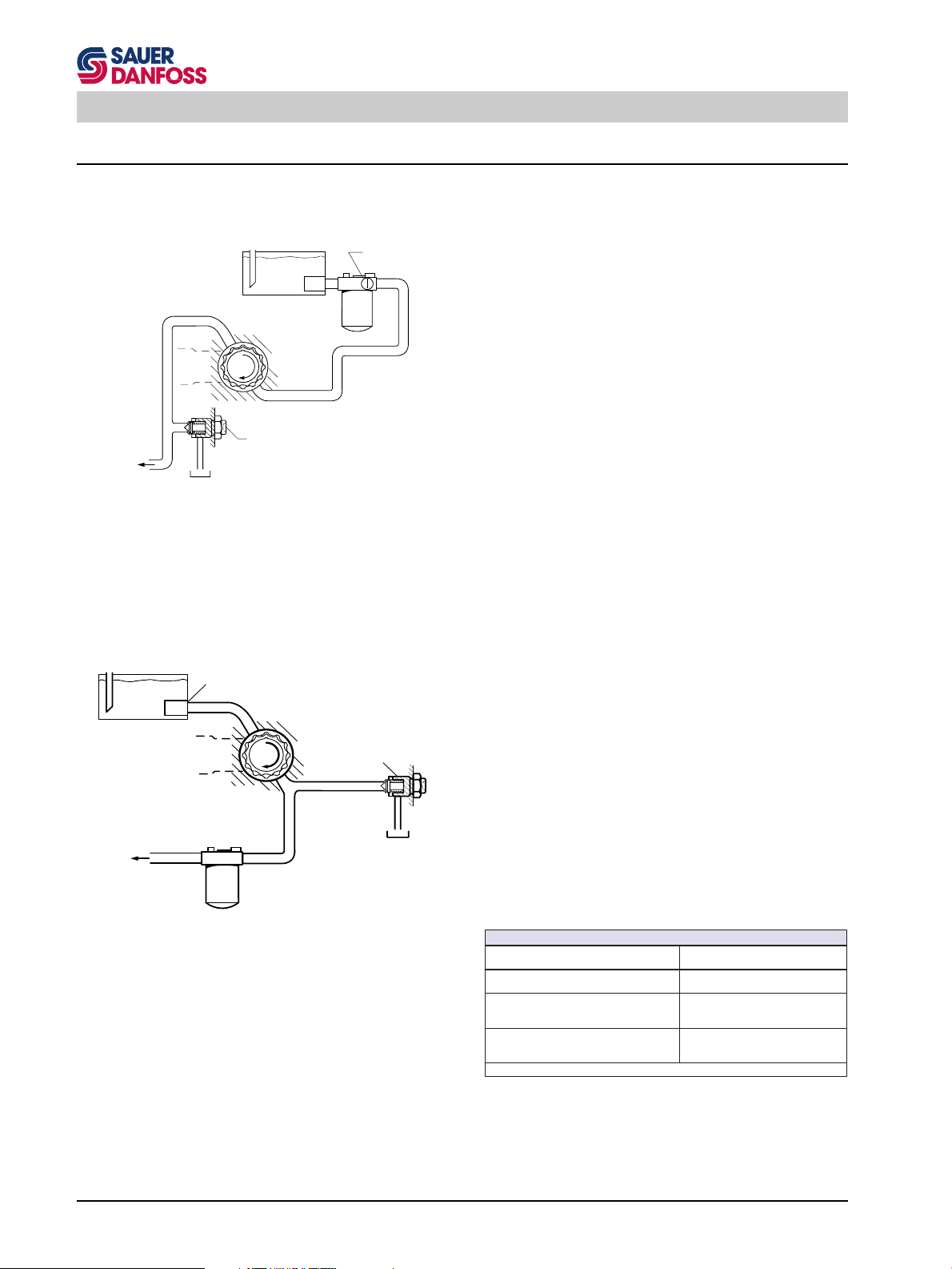
Fluid and Filter Maintenance
To ensure optimum service life of Series 90 products,
regular maintenance of the fluid and filter must be performed. Contaminated fluid is the main cause of unit
ManoVacuummeter
failure. Care should be taken to maintain fluid cleanliness
while performing any service procedure.
to low
pressure
side and
control
Suction Filtration Schematic
Hydraulic fluid reservoir
to low
pressure
side and
control
Hydraulic fluid reservoir
Adjustable
Charge pressure relief valve
To pump case
Screen
Charge pump
Charge pump
Filter
P000 797E
Adjustable
Charge pressure
relief valve
To pump case
Check the reservoir daily for proper fluid level, the presence of water (noted by a cloudy to milky appearance, or
free water in bottom of reservoir), and rancid fluid odor
(indicating excessive heat). If either of these conditions
occur, change the fluid and filter immediately.
It is recommended that the fluid and filter be changed
per the vehicle/machine manufacturer’s recommendations or at the following intervals:
First change
500 operating hours after start up
second and subsequent changes
every 2000 operating hours or once a year.
This recommendation applies for the most applications.
High temperatures and pressures will result in accelerated fluid aging and an earlier fluid change may be
required. At lower fluid loads longer change intervalls are
possible. Therefore we suggest to check the fluid with the
manufacturer for suitability. This should be done at latest
half way between fluid changes.
It may be necessary to change the fluid more frequently
than the above intervals if the fluid becomes contaminated with foreign matter (dirt, water, grease, etc.) or if
the fluid has been subjected to temperature levels greater
than the recommended maximum. Never reuse fluid.
The filter should be changed whenever the fluid is changed
or whenever the filter indicator shows that it is necessary
to change the filter.
26
Filter
Charge Pressure Filtration Schematic
(Partial flow)
P000 798E
level
dednemmoceR β
x
dednemmoceR β
x
noitartlif
noitartliferusserp
ssenilnaelcdiulfderiuqeR
oitar-
noitartlifnoitcusrof
oitar-
erusserpegrahcrof
telnidednemmoceR
egrahcrofezisneercs
dnaleveLssenilnaelC βββββ
β
β
001 µ 521-m µm
oitaR-
x
(57= β01≥ )2
54-53
(57= β01≥ )01
02-51
31/81ssalC6044OSI
E700200T
Page 27

Series 90 Toubleshooting
Troubleshooting
This section provides general steps to follow if certain undesirable system conditions are observed. Follow the steps in
a section until the problem is solved. Some of the items will be system specific. For areas covered in this manual, a section
is referenced. Always observe the safety precautions listed in the section "Introduction" and related to your
specific equipment.
"NEUTRAL" Difficult or Impossible to Find
Check Description Action
1. Input to pump control.
2. Pump displacement control.
contact a SAUER-SUNDSTRAND Authorized Service Center.
System Operating Hot
Check Description Action
1. Oil level in reservoir.
2. Heat exchanger.
3. Charge pressure.
4. Charge pump inlet vacuum.
Input to control module is operating
improperly.
Control linkages are not secure, control
orifices are blocked, etc.
If the above actions do not remedy the problem
Insufficient hydraulic fluid will not meet
cooling demands of system.
Heat exchanger not sufficiently cooling
the system.
Low charge pressure will overwork system.
High inlet vacuum will overwork system. A dirty filter will increase the inlet
vacuum. Inadequate line size will restrict flow.
Check control input and repair or replace as necessary.
Adjust, repair, or replace control module as necessary.
Fill reservoir to proper level.
Check air flow and input air temperature for heat exchanger. Clean, repair
or replace heat exchanger.
Measure charge pressure. Inspect and
adjust or replace charge relief valve. Or
repair leaky charge pump.
Check charge inlet vacuum. If high,
inspect inlet filter and replace as necessary. Check for adequate line size,
length or other restrictions.
5. System relief pressure settings.
6. For internal leakage in motor.
7. System pressure.
contact a SAUER-SUNDSTRAND Authorized Service Center.
If the system relief settings are too low,
the relief valves will be overworked.
Leakage will reduce low side system
pressure and overwork the system.
High system pressure will overheat
system.
If the above actions do not remedy the problem
Verify settings of pressure limiters and
high pressure relief valves and adjust
or replace multi-function valves as necessary.
Monitor motor case flow without loop
flushing in the circuit (use defeat spool).
If flow is excessive, replace motor.
Measure system pressure. If pressure
is high reduce loads.
27
Page 28

Series 90 Toubleshooting
Transmission Operates Normally in One Direction Only
Check Description Action
1. Input to pump control.
Input to control module is operating
improperly.
Check control input and repair or replace as necessary.
2. Pump displacement control.
3. Interchange system pressure limiters, high pressure relief valves, and
system check valves.
4. Charge pressure.
contact a SAUER-SUNDSTRAND Authorized Service Center.
Control linkages are not secure, control
orifices are blocked, etc.
Interchanging the multi-function valves
will show if the problem is related to the
valve functions contained in the multifunction valves.
If charge pressure decays in one direction the loop flushing valve may be
“sticking” in one direction.
If the above actions do not remedy the problem
System Will Not Operate in Either Direction
Check Description Action
1. Oil level in reservoir.
2. Input to pump control.
3. Pump displacement control.
Insufficient hydraulic fluid to supply
system loop.
Input to control module is operating
improperly.
Control linkages are not secure, control
orifices are blocked, etc.
Repair or replace control module as
necessary.
Interchange multi-function valves. If the
problem changes direction, repair or
replace the valve on the side that does
not operate.
Measure charge pressure in forward
and reverse. If pressure decays in one
direction, inspect and repair the motor
loop flushing valve.
Fill reservoir to proper level.
Check control input and repair or replace as necessary.
Repair or replace control module as
necessary.
4. Ensure bypass valve(s) are closed.
5. Charge pressure with pump in neutral.
6. Charge pressure with pump in
stroke.
7. Pump charge relief valve.
8. Charge pump inlet filter.
9. Charge pump.
If bypass valve(s) is open, the system
loop will be depressurized.
Low charge pressure insufficient to recharge system loop.
Low charge pressure with the pump in
stroke indicates a motor charge relief
valve or system pressure relief valve
may be improperly set.
A pump charge relief valve that is leaky
or set too low will depressurize the
system.
A clogged filter will undersupply system
loop.
A malfunctioning charge pump will provide insufficient charge flow.
Close bypass valves. Replace multifunction valve if defective.
Measure charge pressure with the pump
in neutral. If pressure is low, go to step
6; otherwise continue with step 5.
Measure charge pressure with pump in
stroke. If pressure is low, adjust or
replace motor charge relief valve, otherwise go to step 9.
Adjust or replace pump charge relief
valve as necessary.
Inspect filter and replace if necessary.
Repair or replace the charge pump. If
OK go to last step.
28
Page 29

Series 90 Toubleshooting
10. Pump displacement control.
11. System pressure.
12. System multi-function valves.
If the above actions do not remedy the problem
contact a SAUER-SUNDSTRAND Authorized Service Center.
Low Motor Output Torque
Check Description Action
1. System pressure at motor.
2. Variable motor stuck at minimum
displacement.
3. For internal leakage.
Control linkages are not secure, control
orifices are blocked, etc.
Low system pressure will not provide
power necessary to move load.
Defective multi-function valves will
cause system pressure to be low.
Low system pressure at the motor will
reduce torque.
Minimum motor displacement yields low
output torque.
Internal leakage will reduce system
pressure.
Repair or replace control module as
necessary.
Measure system pressure. Continue
with next step.
Repair or replace multi-function valve(s).
Measure system pressure at motor. If
pressure limiter setting is low, increase
setting.
Check control supply pressure or repair displacement control. Check motor control orifices.
Check for leakage in O-rings, gaskets,
and other fittings. Repair unit as required, or replace leaky unit.
If the above actions do not remedy the problem
contact a SAUER-SUNDSTRAND Authorized Service Center.
Improper Motor Output Speed
Check Description Action
1. Oil level in reservoir.
2. Pump output flow.
3. Variable motor displacement control.
4. For internal leakage.
If the above actions do not remedy the problem
contact a SAUER-SUNDSTRAND Authorized Service Center.
Insufficient hydraulic fluid will reduce
motor speed.
Incorrect outflow will affect output
speed. Incorrect output flow indicates
the swashplate is out of position.
If variable motor displacement control
is not functioning correctly, variable
motor swashplate may be in wrong
position.
Internal leakage will reduce system
pressure.
Fill oil to proper level.
Measure pump output and check for
proper pump speed and see that the
pump is in full stroke.
See if variable motor displacement control is responding. If not, repair or replace control.
Check for leakage in O-rings, gaskets,
and other fittings. Repair unit as required, or replace leaky unit.
29
Page 30

Series 90 Toubleshooting
Excessive Noise and/or Vibration
Check Description Action
1. Oil in reservoir.
Insufficient hydraulic fluid will lead to
cavitation.
Fill reservoir to proper level.
2. Air in system.
3. Pump inlet vacuum.
4. Shaft couplings.
5. Shaft alignment.
If the above actions do not remedy the problem
contact a SAUER-SUNDSTRAND Authorized Service Center.
System Response is Sluggish
Check Description Action
1. Oil level in reservoir.
Air bubbles will lead to cavitation.
High inlet vacuum will create noise. A
dirty filter will increase the inlet vacuum.
A loose shaft coupling will cause excessive noise.
Unaligned shafts will create excessive
frictional noise.
Insufficient hydraulic fluid will reduce
output pressure.
Look for foam in reservoir. Check for
leaks on inlet side of system loop. Afterwards, let reservoir settle until bubbles
are gone. Run system at low speed to
move system fluid to reservoir. Repeat.
Inspect and replace filter as necessary.
Check for proper suction line size.
Replace loose shaft coupling in charge
pump or replace pump or motor.
Align shafts.
Fill reservoir to proper level.
2. Multi-function valves’ pressure settings.
3. Pump inlet vacuum.
4. Prime mover speed.
5. Charge and control pressures.
6. System internal leakage.
contact a SAUER-SUNDSTRAND Authorized Service Center.
Incorrect pressure settings will affect
system reaction time.
High pump inlet vacuum will reduce
system pressure.
Low engine speed will reduce system
performance.
Incorrect charge or control pressures
will affect system performance.
Internal leakage will reduce system
pressure.
If the above actions do not remedy the problem
Adjust or replace multi-function valves.
Measure charge inlet vacuum. If high
replace inlet filter.
Adjust engine speed.
Measure charge and control pressures
and correct if necessary.
Check for leakage in O-rings, gaskets,
and other fittings.
30
Page 31

Series 90 Inspections and Adjustments
edoCledoM*erusserPegrahCderusaeM
02
rab7.12sib1.81
)isp513ot262(
42
rab9.62sib0.22
)isp093ot913(
82
rab7.03sib8.52
)isp544ot473(
E662200T
ehtsunimgnidaereguagtroperusserpegrahclautcaehtsisihT*
.gnidaereguagtroperusserpesac
Inspections and Adjustments
This section offers instruction on how to perform inspections and adjustments on pump and motor components. Read
through the entire related section before beginning a service activity. Refer to the corresponding section for location of
gauge ports and suggested gauge size.
Pump Adjustments
Charge Pressure Relief Valve Adjustment
The following procedure explains how to check and adjust
the charge pressure relief valve.
WARNING
The following procedure may require the vehicle/
machine to be disabled (wheels raised off the ground,
work function disconnected, etc.) while performing
the procedure in order to prevent injury to the
technician and bystanders. Take necessary safety
precautions before moving the vehicle/machine.
S000 007E
1. To measure pump charge pressure, install a pressure gauge in the pump charge pressure gauge port
(M3). Also install a gauge to measure case pressure
(tee into L1 or L2 or use servo gauge port). Operate
the system with the pump in “neutral” (zero displacement) when measuring pump charge pressure.
2. The table shows the acceptable pump charge pressure range for some nominal charge relief valve
settings (see sample model code at right). These
pressures assume 1500 pump rpm and a reservoir
temperature of 50°C (120°F ), and are referenced to
case pressure (see footnote on next page). Smaller
displacement charge pumps will produce charge
pressure readings in the lower portion of the range,
while larger displacement charge pumps will produce
readings in the higher portion of the range.
Charge Pressure Gauge Port (Reducer fitting shown - if
filtration device attached)
90L055 EA 1 N
90000243
Nominal
Charge Pressure
6 S 3 C6 C 03
HNN 35 35 24
Model Code on Unit Name Plate (“24 bar”)
* This is the actual charge pressure port gauge reading minus
the case pressure port gauge reading.
Note: These pressures assume a pump speed of
1450 - 1500 rpm. At higher pump input speeds
(with higher charge flows) the charge pressure
will rise over the rated setting.
31
Page 32

Series 90 Inspections and Adjustments
3. Earlier production Series 90 pumps are equipped
with a shim adjustable charge pressure relief valve.
Shim kits are available from SAUER-SUNDSTRAND.
Adjustment of charge pressure is accomplished by
removing the plug [1 inch Hex] and changing the shim
thickness behind the spring. The plug for this type of
charge relief valve should be torqued to 68 Nm
(50 lbf•ft).
Later production Series 90 pumps are equipped with
Shim Adjustable Charge
90000262 90000264
Pressure Relief Valve
(Pump)
Screw Adjustable Charge
Pressure Relief Valve
(Pump)
an external screw adjustable charge pressure relief
valve. Adjustment of the charge pressure is accomplished by loosening the lock nut -
eziSemarFeziShcnerW
001-030hcni61/1-1
052-031hcni8/5-1
and turning the adjustment plug with a large screwdriver or a 1/2 inch hex wrench.
E762200T
Clockwise rotation of the plug increases the setting,
and counterclockwise rotation decreases the setting
(at a rate of approximately 3.9 bar (50 psi) per turn).
The lock nut for this type of charge relief valve should
be torqued to 52 Nm (39 lbf•ft).
4. Once the desired charge pressure setting is achieved,
remove the gauges.
32
Page 33

Series 90 Inspections and Adjustments
Multi-Function Valve Pressure Adjustment
Adjustment of the pressure limiter setting and the high
pressure relief valve setting is accomplished simultaneously. The latter is automatically set approximately
35 bar (500 psi) above the former.
In order to adjust the pressure limiter setting, the motor
output shaft must be locked so it does not rotate. This
may be accomplished by locking the vehicle’s brakes or
rigidly fixing the work function so it cannot rotate.
WARNING
Take necessary precautions that the motor shaft
remains stationary during the adjustment procedure.
1. Install two 1000 bar (or 10 000 psi) pressure gauges
in the high pressure gauge ports (M1 and M2). Install
a 50 bar (or 1000 psi) pressure gauge in the pump
charge pressure gauge port (M3).
S000 010E
90000258
Multi-Function Valves on PV
2. Start the prime mover and operate at normal speed.
3. Loosen locking nut.
eziSemarFeziShcnerW
ylrae
001-240
rewen
001-030
031ylraemm31
052-031mm42
mm01
mm91
E862200T
4. Insert a internal hex wrench into the pressure adjusting screw.
eziSemarFeziShcnerWxeHlanretnI
ylrae
001-240
rewen
001-030
031ylraemm4
052-031mm8
mm3
mm5
E962200T
Note: A plastic dust plug is installed in the adjusting
screw on 030 and late 042 through 250 units.
90000259
Loosen Pressure Adjusting Screw Lock Nut
33
Page 34

Series 90 Inspections and Adjustments
90L055 EA 1 N
6 S 3 C6 C 03
HNN 35 35 24
Pressure Limiter Setting
Ports A and B (differential
pressure in 10s of bars,
e.g. “35” = 350 bar)
Rotate Pressure Adjusting Screw
90000260
5. The factory preset pressure limiter setting is shown
on the model code as at right. It is referenced to
charge pressure, so the pressure limiter setting is the
difference between the high and low pressure sides
of the system loop. Activate or move the control input
so that pressure increases in the high pressure side
of the closed circuit to the pressure limiter pressure
setting. The pressure limiter setting is reached when
the pressure stops increasing and remains steady at
a given pressure level (as shown on the gauges).
6. Return the pump to its “neutral” (zero flow) position
and adjust the pressure limiter setting by rotating the
pressure adjusting screw with the internal hex wrench.
Clockwise rotation of the pressure adjustment screw
will increase the pressure setting, and counterclockwise rotation will decrease the pressure setting. Each
complete rotation of the pressure adjusting screw
changes the pressure as shown in the following table.
eziSemarF
ylrae
001-240
rewen
001-030
052-031rab08veRrep)isp7511(
rab09veRrep)isp0031(
ehtfoveRrepegnahCxorppA
wercSgnitsujdA
veRrep)isp7511(rab08
E072200T
Tighten Lock Nut
90000261
7. To verify the actual pressure setting, actuate or move
the control input so that the pump again develops
pressure in the high pressure circuit to the newly
adjusted pressure limiter pressure setting, and read
the high pressure gauge. Then allow the pump to
return to its “neutral” position. The pressure in the
high pressure circuit should return to the charge
pressure setting.
8. While holding the pressure adjusting screw stationary, tighten the pressure adjusting screw lock.
eziSemarFeuqroT
ylrae
001-240
rewen
001-030
052-03103(mN04)tf•fbl
mN02)tf•fbl51(
)ni•fbl62(mN3
E172200T
Do not overtorque.
9. Shut down the prime mover, remove the gauges and
install the gauge port plugs. Replace the plastic dust
plugs (if used).
The same procedure is used for setting the pressure limit
of the other multi-function valve, but the control input
signal must be activated or moved in the opposite direction so that high pressure develops in the opposite side
of the closed circuit.
34
Page 35

Series 90 Inspections and Adjustments
Engaging the Bypass Function
The bypass function is performed by the multi-function
valve cartridges. The prime mover should be shut down
when opening or closing the bypass valves.
The bypass valves on both of the multi-function valves
must be opened to engaged the bypass function.
1. Using a
eziSemarFeziShcnerW
rewen
001-030
052-031hcni8/3-1
wrench on the middle sized hex of the multi-function
valve cartridge, and a
eziSemarFeziShcnerW
rewen
001-030
052-031hcni8/5-1
hcni61/1-1
E272200T
90000266
Loosening and Rotating Bypass Hex on Multi-Function
hcni4/1-1
E372200T
Bypass
Actuator
Valve
Opening Bypass Valve
allows flow to circuit
through Multi-Function Valves
wrench on the large hex to prevent rotation of the
cartridge assembly, rotate the middle hex three
revolutions counterclockwise to open the bypass
valve. Do not rotate more than 3-1/2 revolutions,
as additional rotation will permit external leakage.
2. For units with an MDC-type control, prior to moving
the vehicle or otherwise causing the motor shaft to
turn, move the control handle of the manual displacement control on the pump to the maximum full
forward position. Hold the handle in this position
during bypass valve operation.
Caution
"Tow" at extremely low speeds and for short
distances only.
S000 011E
3. To close the bypass valve, rotate the middle hex
clockwise until it is seated. Then torque the middle
hex.
eziSemarFeuqroT
rewen
001-030
052-031)tf•fbl57(mN001
)tf•fbl03(mN14
E472200T
90000827E
Multi-Function Valve with Bypass Function Engaged
35
Page 36

Series 90 Inspections and Adjustments
Pressure Override (POR) Valve Pressure
Adjustment (Option for 180 Frame Size)
The Pressure Override Valve is explained in the corresponding section.
Pressure Override Valve
Right Side View
Pressure Override Valve for 180 Frame Size
Adjusting Screw
Lock Nut
90000828E
1. Install two 1000 bar (or 10 000 psi) pressure gauges
in the high pressure gauge ports (M1 and M2). Install
a 50 bar (or 1000 psi) pressure gauge in the pump
charge pressure gauge port (M3).
2. Start the prime mover and operate at normal speed.
3. With the pump operating at approximately 20% displacement, load the work function and note the
pressure as the POR valve operates (pump displacement reduces to “zero”).
4. Adjustment of the pressure override setting is made
by loosening the lock nut with a 9/16 inch hex wrench
and turning the adjustment screw with a 3/16 inch
internal hex wrench. The POR setting should be at
least 50 bar (750 psi) below the high pressure relief
valve setting of the multi-function valves for proper
operation.
5. Following the adjustment, torque the lock nut to
43 Nm (32 lbf•ft).
6. Shut down the prime mover and remove the gauges
and install the gauge port plugs.
36
Page 37

Series 90 Inspections and Adjustments
Displacement Limiter Adjustment
The maximum displacement can be limited in either
direction.
1. Loosen the seal lock nut retaining the displacement
limiter adjusting screw.
eziSemarFeziShcnerW
001-030mm31
031mm71
052-081mm91
E572200T
2. Rotate the adjusting screw.
eziSemarFeziShcnerWxeHlanretnI
001-030mm4
031mm5
052-081mm6
E672200T
Rotating the adjusting screw clockwise will decrease
the maximum displacement of the pump while rotating the adjusting screw counterclockwise will increase the maximum displacement.
Loosen Displacement Limiter Lock Nut
90000267
Caution
Care should be taken in adjusting displacement
limiters to avoid undesirable flow or speed conditions.
The seal lock nut must be retorqued after every
adjustment to prevent an unexpected change in
operating conditions and to prevent external leakage
during unit operation.
S000 012E
3. After establishing the desired maximum displacement setting, tighten the lock nut on the adjusting
screw as follows.
eziSemarFeuqroT
001-030)tf•fbl81(mN42
031mN84)tf•fbl53(
052-081)tf•fbl29(mN521
E872200T
4. One turn of the adjusting screw will change the
maximum displacement approximately as follows.
eziSemarF
030mc8.2
240mc5.3
550mc2.4
570mc1.5
001mc2.6
031mc8.8
081mc5.21
052mc3.71
3
3
3
3
3
3
3
3
3
ni71.0(veR/
3
ni12.0(veR/
3
ni62.0(veR/
3
ni13.0(veR/
3
ni83.0(veR/
3
ni35.0(veR/
3
ni67.0(veR/
3
ni60.1(veR/
wercSgnitsujdA
foveRreppsiDniegnahCxorppA
)veR/
)veR/
)veR/
)veR/
)veR/
)veR/
)veR/
)veR/
E772200T
90000268
Rotate Adjusting Screw
90000269
Tighten Lock Nut
37
Page 38

Series 90 Inspections and Adjustments
Pump Control Adjustments
Standard Manual Displacement Control (MDC)
Adjustment
There are no adjustable elements in the manual displacement control. The control spool is held in its “neutral”
position by centering springs and washers on each end of
the spool. Since there is no centering spring on the control
input shaft, the shaft will automatically assume the appropriate position when the control is installed on the pump.
Variable Displacement Pump with Standard Manual
Displacement Control
90000237
38
Page 39

Series 90 Inspections and Adjustments
Non-Linear Manual Displacement Control
(MDC)
A centering spring, located on the control input shaft,
locates the control shaft in its “neutral” position. A bias
spring on the control spool maintains a force on the spool
and the control linkage to eliminate looseness (“freeplay”) in the linkage.
The “neutral” adjustment is the only adjustment that can
be made on the nonlinear manual displacement control.
All other functions are preset at the factory.
This adjustment must be made on a test stand or on the
vehicle/machine with the prime mover operating.
WARNING
The following procedure may require the vehicle/
machine to be disabled (wheels raised off the ground,
work function disconnected, etc.) while performing
the procedure in order to prevent injury to the
technician and bystanders. Take necessary safety
precautions before moving the vehicle/machine.
S000 007E
Variable Displacement Pump with Non-Linear Manual
Displacement Control
90000829
1. Install two 50 bar (or 1000 psi) gauges in each of the
displacement control cylinder gauge ports (M4 and
M5). Disconnect the external control linkage from the
control handle and make certain the control shaft is
in its “neutral” position. Start the prime mover and
operate at normal speed.
2. Loosen the lock nut on the neutral adjusting screw
with a 13 mm hex wrench.
3. Using a 4 mm internal hex wrench, rotate the neutral
adjusting screw clockwise until the pressure increases
on one of the pressure gauges. Note the angular
position of the wrench.
4. Rotate the adjusting screw counterclockwise until the
pressure increases by an equal amount on the other
gauge. Note the angular position of the wrench.
5. Rotate the adjusting screw clockwise half the distance between the locations noted above. The gauges
should read the same pressure (case pressure),
indicating that the control is in its “neutral” position.
6. Hold the adjusting screw stationary and tighten the
lock nut to 13.5 Nm (10 lbf•ft). Do not overtorque
the nut.
Rotate Neutral Adjusting
90000357
Screw
Tighten Neutral Adjusting
90000358
Screw Lock Nut
7. Once the neutral position is set, stop the prime
mover, remove the gauges, and install the gauge
port plugs. Reconnect the external control linkage.
39
Page 40

Series 90 Inspections and Adjustments
MDC Neutral Start Switch (NSS) Adjustments
A
Control Shaft
Eccentric Plug
Switch Pin
Special Lock Nut
for Eccentric Plug
MDC with Neutral Start switch
View at Section A-A
Components of the Standard Manual Displacement Control
with Neutral Start Switch
Switch Cam
Switch Lock Nut
Neutral Start Switch
Orifice Check Valve Seat
Control Spool Assembly
Control Link Assembly
A
90000830E
The neutral start switch (NSS) provides a means to
prevent the system prime mover from starting while the
pump control handle and control input shaft are in a
position which would command the pump to go “instroke” in either the “forward” or “reverse” direction.
When the control input shaft is in its “neutral” position, the
inner end of the switch pin moves into a slot on the
eccentric cam attached to the control shaft. This allows
the spring loaded NSS to close, completing the electrical
starting circuit for the prime mover.
When the control input shaft is NOT in its “neutral”
position, the eccentric cam moves the switch pin out of
the slot. This forces the NSS to open, breaking the
electrical starting circuit for the prime mover.
The neutral start switch is threaded into the special lock
nut for the eccentric plug.
Turning the NSS clockwise (CW) into the special nut will
move the NSS closer to the switch cam on the control
shaft, and will narrow the NSS deadband. Turning the
NSS counterclockwise (CCW) out of the special nut will
move the NSS farther from the switch cam on the control
shaft, and will widen the NSS deadband.
The switch pin is located in an eccentric plug which is
turned to move the center of the NSS deadband.
(continued)
40
Page 41

Series 90 Inspections and Adjustments
The NSS must be adjusted to meet the following three
requirements:
i. The distance the control handle can be turned with-
out opening the NSS is called the “NSS Deadband.”
The distance the control handle can be moved without moving the control spool enough to port hydraulic
fluid to the pump displacement control cylinders is
called the “Control Deadband.” These deadbands
must be centered in relation to each other.
NSS Deadband
(Switch closed, "ON")
Control Deadband
("Neutral")
Total Control
Shaft Rotation
Control Shaft
("Free-Play")
Since the position of the control deadband cannot be
adjusted, the position of the NSS deadband must be
adjusted to match it.
ii. The NSS deadband must be wide enough so the NSS
will not open within the loose area of control handle
movement caused by normal operating clearances in
the control linkage (control shaft “free-play”).
By setting the NSS to open outside this area, the
control spool springs or control shaft centering spring
can always act to return the handle to “neutral” and
re-close the NSS.
iii. The NSS deadband must be narrow enough so the
NSS will open before the unit builds 7 bar (100 psi)
differential system pressure in either direction.
(continued)
Control Shaft
90000831E
Neutral Start Switch Adjustment Requirements
41
Page 42

Series 90 Inspections and Adjustments
NSS Deadband Adjustment (Conditions ii & iii)
The NSS deadband must be wide enough so the NSS will
not open within the control shaft “free-play” area, and it
must be narrow enough so the NSS will open before the
unit builds 7 bar (100 psi) differential system pressure in
either direction.
1. Install two 1000 bar (10 000 psi) pressure gauges in
the system pressure gauge ports M1 and M2.
2. Using two 1-1/8 inch wrenches, hold the neutral start
switch from turning and loosen the locknut.
3. Disconnect the external control linkage and make
certain the control shaft is in its “neutral” position.
4. Attach a continuity checker to the terminals of the
switch. With the control shaft in its “neutral” position,
Loosening the NSS Lock Nut
90000253
turn the switch clockwise (CW) until electrical continuity is broken, then turn the switch counterclockwise
(CCW) until electrical continuity is obtained. Turn the
switch counterclockwise (CCW) an additional 1/4
turn (90°) after continuity has been obtained.
Switch Cam
Switch Pin
Control Shaft
Switch Lock Nut
Neutral Start Switch
1-1/8 in. hex wrench
Torque: 27 Nm (20 lbf•ft)
NSS
90000832E
5. Hold the switch in place and tighten the locknut to
27 Nm (20 lbf•ft) torque.
6. With the continuity checker attached to the switch,
rotate the control handle (or the control shaft) in each
direction to assure continuity is broken when the
control is not in the “neutral” position.
7. If continuity is obtained in “neutral” and satisfactorily
interrupted in each direction, proceed to check the
switch with the prime mover running. The switch
must open before the unit builds 7 bar (100 psi)
differential system pressure in either direction.
If the switch opens after the unit builds system
pressure in either direction, loosen the switch lock
nut and turn the switch clockwise (CW) 1/12 turn
(30°). Tighten the switch lock nut and recheck the
switch operation. Repeat this procedure if necessary.
8. If continuity is not interrupted with an equal move-
ment of the control handle in each direction, turn off
prime mover, remove the pressure gauges, and
continue with the next section.
9. If neutral start switch operation is satisfactory, turn
off the prime mover, remove the pressure gauges,
and reconnect the external control linkage.
Checking Continuity of NSS (System Pressure Gauges
installed on far side)
42
90000870
Page 43

Series 90 Inspections and Adjustments
Neutral Start Switch Eccentric Plug Adjustment (Condition i)
The NSS deadband and the control deadband must be
centered in relation to each other.
Since the position of the control deadband cannot be
adjusted, the position of the NSS deadband must be
adjusted to match it. The switch pin is located in an
eccentric plug which is turned to move the center of the
NSS deadband.
The MDC should be installed on the pump and be in its
“neutral” position when adjusting the neutral start switch
eccentric plug.
The accompanying drawing provides dimensions for an
Eccentric Plug Adjustment Tool.
1. Hold the switch and eccentric plug from turning and
use two 1-1/8 inch wrenches to loosen the locknut.
Remove the neutral start switch.
WARNING
Do not start the prime mover while the neutral start
switch is removed from the control. Case pressure
will force the pin out of the eccentric plug, causing
oil loss.
S000 032E
12.7
(0.5)
Eccentric Plug Adjustment Tool
Eccentric Plug
Switch Pin
Special Lock Nut
for Eccentric Plug
MDC with Neutral Start Switch
3.175
(0.125)
1.52
(0.06)
X
Neutral Start Switch
Special Lock Nut
for Eccentric Plug
9.14
(0.36)
25.4+
(1.0)
90000834E
Switch
Lock Nut
2. Note the slots on the eccentric plug for the adjustment tool. Hold the eccentric plug in place with the
adjustment tool, and loosen the lock nut with a
1-1/8 inch wrench.
(continued)
Control
Mounting
Surface
View in Direction X
(Switch and lock nut removed)
NSS with Eccentric Plug
90000256
Eccentric Plug
Switch Pin
90000833E
90000257
NSS RemovedLoosen Eccentric Lock Nut
43
Page 44

Series 90 Inspections and Adjustments
3. Position the eccentric plug so the switch pin is offset
Switch Pin
Control Mounting
Surface
Eccentric Plug
90˚90˚
Eccentric Plug
Adjustment Range
90000835E
Eccentric Plug Adjustment
toward the control mounting surface. This will provide
the best contact between the pin and the cam on the
control shaft.
4. Hold the control shaft in its “neutral” position (in the
center of the control shaft “free-play” area). Locate
the switch pin in the slot of the switch cam by turning
the eccentric plug while checking the pin position
(depth) in the plug. When the pin engages the cam
slot, the pin will be at its maximum depth in the plug.
Hand tighten the plug lock nut to hold the eccentric
plug in position.
5. Turn the control shaft an equal amount in either
direction from “neutral.” The switch pin should move
out of the eccentric plug an equal distance when the
control shaft is turned. Turn the eccentric plug to
center the switch pin with the cam slot. Only a small
amount of adjustment in either direction should be
needed to center the pin.
6. While holding the eccentric plug in place, tighten the
eccentric plug lock nut to 27 Nm (20 lbf•ft). Reinstall
and adjust the switch as outlined in the previous
section.
Adjust the Eccentric Plug
Note: The eccentric plug normally requires between
5-1/2 and 6-1/2 turns to install into the control
housing .
90000256
Caution
Do not turn the eccentric plug into or out of the
housing beyond specifications.
S000 014E
7. Once the switch is correctly adjusted, hold the switch
in place and tighten the locknut to 27 Nm (20 lbf•ft)
torque.
(continued)
44
Page 45

Series 90 Inspections and Adjustments
Checking Switch Continuity
Recheck switch continuity to determine whether additional adjustment of the eccentric plug is necessary.
WARNING
The following procedure may require the vehicle/
machine to be disabled (wheels raised off the ground,
work function disconnected, etc.) while performing
the procedure in order to prevent injury to the
technician and bystanders. Take necessary safety
precautions before moving the vehicle/machine.
1. Install two 50 bar (or 1000 psi) gauges in each of the
displacement control cylinder gauge ports (M4 and
M5). Attach a continuity checker to the terminals of
the neutral start switch.
2. Energize the starter circuit, and start the prime
mover.
3. While operating at normal speed and with the pump
in its “neutral” (zero flow) position, note the pressure
reading on the gauges. This reading should be noted
as the base pressure.
S000 007E
4. Slowly move the control handle in one direction while
observing the pressure gauges and the continuity
checker. Continuity must be broken before the pressure on either gauge increases more than 1 bar
(12 psi) from the base pressure obtained at “neutral.”
5. Slowly move the control handle in the opposite
direction. Again, continuity must be broken before
the gauge pressure increases more than 1 bar (12 psi)
from base pressure.
6. Continuity must again be verified when the control is
returned to neutral.
7. If continuity is not broken at base pressure plus 0 to
1 bar (0 to 12 psi) in either direction, stop the prime
mover and readjust the eccentric plug as described
in the previous section. If the pressure difference is
equal in each direction but greater than 1 bar (12 psi),
loosen the switch locknut and turn the switch clockwise 1/12 turn (30°) to increase the sensitivity. Retighten the locknut and recheck pressure differences
and continuity.
8. After verifying proper control and switch operation,
stop the prime mover. Remove the continuity checker
and pressure gauges. Reinstall the servo pressure
port plugs and reconnect the electrical leads from the
machine starter circuit to the neutral start switch.
Install and adjust, if necessary, the external control
linkage.
Checking Continuity of NSS
(Gauges installed in Servo Gauge Ports)
90000255
45
Page 46

Series 90 Inspections and Adjustments
Hydraulic Displacement Control (HDC) and
Electric Displacement Control (EDC) Adjustment
The “neutral” adjustment is the only adjustment that can
be made on hydraulic and electric displacement controls.
All other functions are preset at the factory.
This adjustment must be made on a test stand or on the
vehicle/machine with the prime mover operating.
The neutral adjustment is performed by adjusting a
neutral adjusting shaft (earlier production EDCs) or a
PV with Hydraulic Displacement Control
90000240
neutral adjusting screw (HDCs and current production
EDCs).
WARNING
The following procedure may require the vehicle/
machine to be disabled (wheels raised off the ground,
work function disconnected, etc.) while performing
the procedure in order to prevent injury to the
technician and bystanders. Take necessary safety
precautions before moving the vehicle/machine.
S000 007E
PV with Electric Displacement Control
90000241
90000249
Install Gauges in Displacement Control Cylinder Gauge
Ports
1. Install two 50 bar (or 1000 psi) gauges in each of the
two displacement control cylinder gauge ports (M4
and M5). Disconnect the external control input (hydraulic or electronic) from the control. Start the prime
mover and operate at normal speed.
2. Loosen the lock nut with a 17 mm hex wrench for the
neutral adjusting shaft or with a 10 mm or 13 mm hex
wrench for the neutral adjusting screw.
46
Page 47

Series 90 Inspections and Adjustments
3. Using a 5 mm internal hex wrench for the neutral
adjusting shaft or a 3 mm or 4 mm internal hex
wrench for the neutral adjusting screw, rotate clockwise until the pressure increases in one of the
pressure gauges. Note the angular position of the
wrench. Then rotate the neutral adjusting shaft or
screw counterclockwise until the pressure increases
by an equal amount on the other gauge. Again note
the angular position of the wrench.
4. Rotate the neutral shaft or adjusting screw clockwise
half the distance between the locations noted above.
The gauges should read the same pressure (case
pressure), indicating that the control is in its “neutral”
position.
5. Hold the neutral adjusting shaft or screw stationary.
Tighten the neutral shaft lock nut (early production
controls) to 22 Nm (195 lbf•in.). Tighten the neutral
adjusting screw lock nut (later production controls) to
7 Nm (62 lbf•in.) for the 6 mm screw or 13.5 Nm
(120 lbf•in.) for the 8 mm screw. Do not overtorque
the nut.
6. Once the neutral position is set, stop the prime
mover, remove the gauges, and install the gauge
port plugs. Reconnect the external control input.
Rotate Neutral Adjusting
Shaft
(Early production)
Rotate Neutral Adjusting
Screw
(Later production)
90000250 90000252
90000251 90000318
Tighten Neutral Adjusting
Shaft Lock Nut
(Early production)
Tighten Neutral Adjusting
Screw Lock Nut
(Later production)
Rotate Neutral Adjusting
Shaft
(Current production HDC)
90000355
Tighten Neutral Adjusting
Shaft Lock Nut
(Current production HDC)
90000356
47
Page 48

Series 90 Inspections and Adjustments
Motor Adjustments
Charge Relief Valve Adjustment
1. To measure motor charge pressure, install a 50 bar
(or 1000 psi) pressure gauge in the motor charge
pressure gauge port (M3). Size 30 and 42 don’t have
the M3 gauge port. Install pressure gauge in the
motor system pressure gauge port. For this kind of
measurement add 1 bar (14.5 psi) to the nominal
values shown in the table. Also install a gauge to
measure case pressure. Operate the system with the
pump in stroke (forward or reverse) when measuring
motor charge pressure.
Charge Pressure Gauge Port (MF)
90M055 NC 0 N
8 N 0 C6 W 00
NNN 00 00 24
edoCledoM
01)isp711(rab1.8
81)isp332(rab1.61
02)isp262(rab1.81
42)isp023(rab1.22
82)isp873(rab1.62
03)isp534(rab0.03
Model Code at the Name Plate (24 bar)
90000248
Nominal charge
Pressure Setting
erusserPegrahCrotoM
)]isp02±[rab4.1±(
2. The following table shows acceptable motor charge
pressures for some nominal charge relief valve settings (see model code at right). These pressures
assume a reservoir temperature of 50°C (120°F).
They are referenced to case pressure and assume a
one pump/one motor system.
3. Earlier production Series 90 motors are equipped
with a shim adjustable charge relief valve. Shim kits
are available as service items. Adjustment of the
charge pressure is accomplished by removing the
plug (7/8 inch hex) and changing the shim thickness
behind the spring. The plug for this type charge relief
port should be torqued to 68 Nm (50 lbf•ft).
Later production Series 90 motors are equipped with
an external screw adjustable charge relief valve.
Adjustment of charge pressure is accomplished by
loosening the lock nut,
eziSemarFeziShcnerW
E972200T
031-030hcni61/1-1
E392200T
and turning the adjustment plug with a large screwdriver or a 1/2 inch hex wrench. Clockwise rotation of
the plug increases the setting, and counterclockwise
rotation decreases the setting (at a rate of approximately 5.4 bar [78 psi] per turn). The lock nut for this
type charge relief valve should be torqued to 52 Nm
(38 lbf•ft).
Shim Adjustable Charge
Pressure Relief Valve
(Motor)
48
90000263 90000343
Screw Adjustable Charge
Pressure Relief Valve
(Motor)
4. Once the desired charge pressure setting is achieved,
remove the gauges.
Page 49

Series 90 Inspections and Adjustments
Displacement Limiter Adjustment (MV)
Both the maximum and minimum displacement may be
limited.
1. Remove the tamper resistant cap from the displacement limiter screw. Loosen the seal lock nut retaining
the displacement limiter adjusting screw with a 19 mm
wrench.
Caution
The displacement limiters act as travel stops for the
swashplate. Do not turn the limiter screws
counterclockwise beyond the point of contact with
the swashplate for either the maximum or minimum
displacement position.
S000 015E
2. All adjustments can only be done when the motor is
running and the pump is in neutral position. Steer the
respective displacement limiter by the control.
Rotate the adjusting screw with a 6 mm internal hex
wrench. Rotating the maximum displacement adjusting screw clockwise will decrease the maximum
displacement of the motor. Rotating the minimum
displacement adjusting screw clockwise will increase
the minimum displacement of the motor.
Tamper-Resistant Cap
Seal Lock Nut
Maximum Displacement
Limiter Screw
Minimum Displacement
Limiter Screw
Seal Lock Nut
Tamper-Resistant Cap
SAE Flange Version shown
(Cartridge Version similar)
90000837E
MV Displacement Limiters
Caution
Care should be taken in adjusting displacement
limiters to avoid undesirable flow or speed
conditions. See corresponding section for speed
and pressure limits.
The seal lock nut must be retorqued after every
adjustment to prevent an unexpected change in
operating conditions and to prevent external leakage
during unit operation.
S000 016E
3. After establishing the desired displacement setting,
tighten the lock nut on the adjusting screw to 54 Nm
(40 lbf•ft). Install a new tamper resistant cap.
4. One turn of the adjusting screw will change the
maximum or minimum displacement according to the
following chart.
eziSemarF
550mc6.5
570mc1.7
3
3
wercSgnitsujdA
3
ni43.0(veR/
3
ni34.0(veR/
foveRreppsiDniegnahCxorppA
)veR/
)veR/
E082200T
Rotate Adjusting Screw for
90000359
Minimum Displacement
Limiter
Tighten Lock Nut for
90000360
Minimum Displacement
Limiter
Displacement Control Adjustments
All variable motor displacement control settings do not
require adjusting.
Maximum Displacement Limiter
90000352
49
Page 50

Series 90 Inspections and Adjustments
Speed Sensor Adjustment
When installing or adjusting the speed sensor on a pump
or motor, it must be set at a specific distance from the
speed ring on the unit’s cylinder. To locate the position of
Gap
the speed sensor on the unit or description see the
corresponding section.
Speed Sensor
Magnetic Speed Ring
90000838E
Cross Section View of Speed Sensor in Variable Pump
Gap
Magnetic Speed Ring
Speed Sensor
90000839E
Cross Section View of Speed Sensor in fixed Motor
Gap
Speed Sensor
Magnetic Speed Ring
90000840E
Cross Section View of Speed Sensor in Variable Motor
1. Loosen the sensor lock nut with an 1-1/16 inch hex
wrench.
2. Turn the sensor clockwise (CW) by hand until it
contacts the speed ring.
3. Turn the sensor counterclockwise (CCW) 1/2 turn
(180°) to establish the nominal gap of 0.71 mm
(0.028 inch).
4. Then turn the sensor clockwise (CW) until the wrench
flats on sensor body are positioned at a 22° angle to
the pump shaft center line.
Note: Many adjustable wrenches have a 22° handle
offset.
5. The final sensor position should be between
1/2 (180°) and 1/4 turn (90°) counterclockwise (CCW)
from the point where the sensor contacts the speed
ring.
6. Hold sensor in position with a 1/2 inch hex wrench
while tightening the lock nut to 13 Nm (10 lbf•ft).
Shaft Centerline
1/2 in. Wrench Flats
22˚
Speed Sensor with
Packard Connector
1/2 in. Wrench Flats
22˚
Speed Sensor with
Packard Connector
Positioning Speed Sensor relative to Pump or Motor Shaft
22˚
Speed Sensor with
Turck Connector
Shaft Centerline
22˚
Speed Sensor with
Turck Connector
90000841E
50
Page 51

Series 90 Minor Repair Instructions
Minor Repair Instructions
Minor repairs may be performed, following the procedures in this section, without voiding the unit warranty.
Although specific models are shown, these procedures
apply to all series and types of units in the Series 90
Family.
Cleanliness is a primary means of ensuring satisfactory
transmission life, on either new or repaired units. Cleaning parts by using a solvent wash and air drying is
adequate, providing clean solvent is used. As with any
precision equipment, the internal mechanism and related
items must be kept free of foreign materials and chemicals.
Protect all exposed sealing surfaces and open cavities
from damage and foreign material.
It is recommended that all gaskets and O-rings be
replaced when servicing. All gasket sealing surfaces
must be cleaned prior to installing new gaskets. Lightly
lubricate all O-rings with clean petroleum jelly prior to
assembly.
51
Page 52

Series 90 Minor Repair Instructions
Hydrostatic Unit Outlines for Minor Repair Reference
Charge Pressure
Relief Valve
Control
Control Orifice
Filtration Options
Charge Pump
(Auxiliary Pad)
Loop Flushing
Valve
Left Side View
Charge Pressure
Relief Valve
(Speed Sensor)
Left Side View
Shaft Seal
SAE-Flange PV
Shaft
Seal
Main Shaft
Loop Flushing
Valve
Right Side View
Charge Pressure
Relief Valve
(Speed Sensor)
Left Side View
Cartridge Flange MFSAE Flange MF
Speed Sensor
90000843E
Shaft
Seal
90000844E
Control Orifices
Charge Pressure
Relief Valve
Loop Flushing
Valve
Control
52
Minimum Angle
Displacement Limiter
Left Side View
Cartridge Flange MV
Maximum Angle
Displacement Limiter
Shaft
Seal
Control Orifices
Charge Pressure
Relief Valve
Loop Flushing
Valve
Control
Left Side View
SAE Flange MV
Maximum Angle
Displacement Limiter
Shaft
Seal
Minimum Angle
Displacement Limiter
90000845E
Page 53
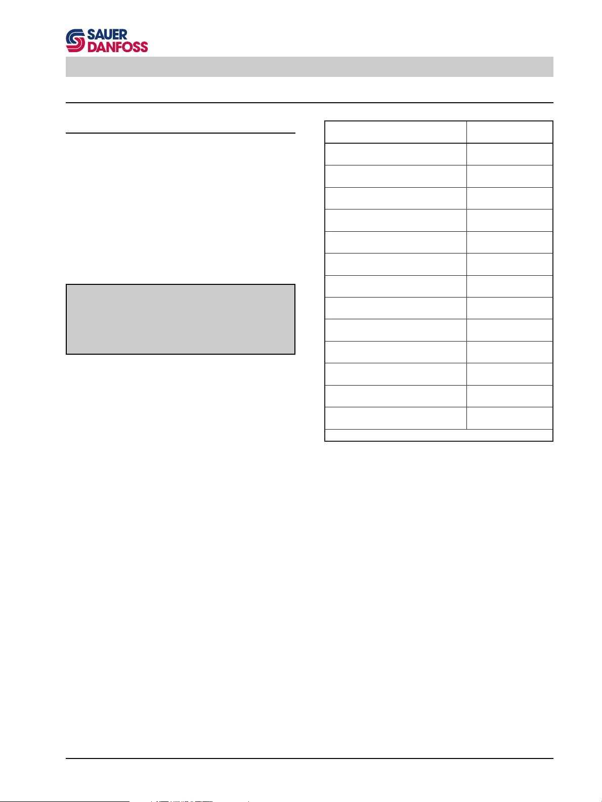
Series 90 Minor Repair Instructions
Pump and Motor Minor Repair
Pump / Fitting Torques
If any plugs or fittings are removed from the pump or
motor during servicing, they should be torqued as indicated in the accompanying table.
Always install new O-rings before reinstalling the plugs or
fittings.
Caution
Plugs or fittings installed into aluminum housings
should always be torqued to the lower values
specified for internal hex plugs of the same size.
S000 017E
noitpircseDeuqroT
gnir-O02-61/7
hcnerWxeHhcni61/9
gnir-O02-61/7
hcnerWxeHlanretnIhcni61/3
gnir-O81-61/9
hcnerWxeHhcni61/11
gnir-O81-61/9
hcnerWxeHlanretnIhcni4/1
gnir-O61-4/3
hcnerWxeHhcni8/7
gnir-O61-4/3
hcnerWxeHlanretnIhcni61/5
gnir-O41-8/7
hcnerWxeHhcni1
gnir-O41-8/7
hcnerWxeHlanretnIhcni8/3
gnir-O21-61/1-1
hcnerWxeHhcni4/11
gnir-O21-61/1-1
hcnerWxeHlanretnIhcni61/9
gnir-O21-61/5-1
hcnerWxeHhcni2/1-1
gnir-O21-61/5-1
hcnerWxeHlanretnIhcni8/5
gnir-O21-8/5-1
hcnerWxeHhcni8/7-1
mN02
)tf•fbl51(
mN21
)tf•fbl9(
mN73
)tf•fbl72(
mN32
)tf•fbl71(
mN86
)tf•fbl05(
mN86
)tf•fbl05(
mN59
)tf•fbl07(
mN86
)tf•fbl05(
mN361
)tf•fbl021(
mN511
)tf•fbl58(
mN091
)tf•fbl041(
mN921
)tf•fbl59(
mN422
)tf•fbl561(
E182200T
53
Page 54

Series 90 Minor Repair Instructions
Shaft Seal and Shaft Replacement
Lip type shaft seals are used on Series 90 pumps and
motors. These seals and/or the shafts can be replaced
without major disassembly of the unit. However, replacement usually requires removal of the pump or motor from
the machine.
1. Position the pump with the shaft facing up.
Note: If the unit is positioned horizontally when the
shaft is removed, the cylinder block could move
out of place, making shaft installation difficult.
2. Remove the three or four screws holding the retainer
plate and seal carrier to the housing, using a 10 mm
hex wrench (030 and 042 units), a 5 mm internal hex
90000270 90000271
Retainer Plate and Seal
Carrier
Remove Seal CarrierRemove Screws Holding
wrench (055 through 100 units), or a 6 mm internal
hex wrench (130 through 250 units). Remove the
retainer plate.
Note: Certain earlier production units use a one piece
retainer plate and seal carrier.
Press Out Old Seal New Seal Installed in Carrier
90000272 90000273
Retaining Plate
Seal Carrier
Seal
Screw
Seal Carrier
(One Piece)
O-ring
Screw
Seal
3. After removing the screws, the spring force on the
shaft may move the seal carrier out of its bore by
approximately 5 mm (1/4 inch). If the seal carrier
does not move from its bore after removing the
screws, pry it from its bore as shown and/or lightly tap
the end of the shaft with a soft mallet.
4. Remove the O-ring from the seal carrier.
5. Place seal carrier and seal in an arbor press and
press out old seal.
6. Inspect the seal carrier, the new seal and the O-ring
for any damage or nicks.
7. Using the arbor press, press the new seal into seal
carrier. Be careful not to damage the seal.
Note: The outside diameter of the seal may be lightly
coated with a sealant (such as Loctite High
Performance Sealant #59231) prior to installation. This aids in preventing leaks caused by
damage to the seal bore in the seal carrier.
54
Series 90 Shaft Seal Components
90000846E
Page 55

Series 90 Minor Repair Instructions
8. Inspect the sealing area on the shaft for rust, wear,
or contamination.
If the shaft is not being replaced proceed to step
12.
9. Remove shaft and roller bearing assembly from
pump or motor. The bearing assembly can be transferred to the new shaft.
10. Remove the retaining ring that secures roller bearing
assembly with a snap ring pliers. Remove the roller
bearing assembly.
11. Place roller bearing assembly on new shaft and
secure with the retaining ring.
12. Wrap spline or key end of shaft with plastic film to
prevent damage to the sealing lip on the seal during
installation.
13. Prior to assembly, lubricate the O-ring on the O.D. of
the seal carrier and the I.D. of the seal with clean
petroleum jelly.
14. Assemble the seal carrier and seal over the shaft and
into the housing bore. Install the retainer plate (if
used).
15. Install the screws and torque like the tables.
Pumps
eziSemarFspmuPeuqroT
240-030mN21)tf•fbl9(
001-550mN61)tf•fbl21(
052-031)tf•fbl42(mN23
E282200T
Roller Bearing
Assembly
Tapered
Splined
Shaft
Shaft
OR
OR
Fixed Motor Shaft Configuration
Roller Bearing
Assembly
Splined
Shaft
OR
OR
Variable Pump Shaft Configuration
Roller Bearing
Assembly
Splined
Shaft
OR
Variable Motor Shaft Configuration
Retaining Ring
OR
Roller Bearing
Straight Key
Shaft
Retaining Ring
OR
Straigt Key
Shaft
90000866E
Rollen Bearing
Tapered
Shaft
90000867E
Retaining
Ring
Tapered
Shaft
90000868E
Motors
eziSemarFsrotoMeuqroT
001-030mN5.9)tf•fbl7(
031)tf•fbl6.61(mN5.22
E382200T
Note: Torque the screws in a sequenced pattern then
recheck.
Install Seal Carrier
90000274 90000275
Torque Retainer Screw
55
Page 56

Series 90 Minor Repair Instructions
Pump Minor Repairs
Multi-Function Valve Cartridges
1. The multi-function valve cartridge is removed with a
hex wrench on the largest hex on the cartridge.
eziSemarFeziShcnerW
001-030hcni4/1-1
052-031hcni8/5-1
2. Inspect cartridge for damage to parts and O-rings.
E482200T
Remove Multi-Function
Valve Cartridge
Multi-Function Valve Cartridge Components
Multi-Function Valve Cartridge Components
Pressure Limiter
Lock Nut
Pressure Limiter
90000276 90000277
(Earlier production)
(Later production)
Pressure Limiter
Housing
Install and Torque Cartridge
Valve Spring
Spring Seat
High Pressure
Relief/Check
Valve Poppet
Check Valve
Poppet
90000278
90000279
The multi-function valve cartridge may be disassembled for cleaning. However, if the pressure limiter
housing assembly is disassembled, the pressure
settings must be readjusted. Usually, if there is
contamination problem, it will be in the valve seat
assembly. If it is not necessary to clean the interior of
the cartridge, proceed to step 7.
Note: Multi-function valve components are not sold
separately as service parts (except O-rings).
3. On early versions of the multi-function valves, the
valve seat assembly is held by a retaining ring.
Remove retaining ring with a snap ring pliers.
On late versions, the valve seat section is pressed over
a lip. Place the cartridge in a vise and pry the lower
section off with an appropriate tool. Maintain sufficient
control to prevent the contents from flying loose.
4. Remove pressure limiter lock nut and bypass actuator.
5. Unscrew the pressure limiter adjustment screw from
the bypass actuator. Clean and inspect all disassembled parts.
6. Reassemble with new, lightly lubricated O-rings by
reversing the above procedure. For early versions
assemble with the retaining ring. For late versions,
place the cartridge in a vise and press on lower
assembly.
Pressure Limiter
Pressure Limiter
Adjustment Screw
Multi-Function Valve Cartridge Sectional View
Valve Poppet
Bypass
Actuator
56
Valve Seat
Spring
Pressure Limiter
Valve Poppet
90000869E
Caution
The pressure settings must be readjusted after
disassembling the pressure limiter housing of the
multi-function valve cartridge.
S000 018E
7.
Install cartridge in multi-function valve cavity and torque.
eziSemarFeuqroT
001-030)tf•fbl66(mN98
052-031)tf•fbl551(mN012
Do not overtorque the multi-function valve cartridge.
E582200T
Page 57

Series 90 Minor Repair Instructions
Pressure Override
Valve
O-rings
Screws
Pressure Override Valve (Option for 180 Frame
Size)
1. Remove the four screws attaching the pressure
override valve to the pump end cap with a 5 mm
internal hex wrench. Remove the O-rings.
2. Inspect valve for damage to parts.
3. Install new O-rings. Install the valve onto the pump
end cap and torque the screws to 16 Nm (12 lbf•ft).
Charge Relief Valve
The pump charge relief valve may be shim adjustable
(early models) or screw adjustable (late models).
1. Remove the shim adjustable charge relief valve plug
with a 1 inch hex wrench.
Before removing the screw adjustable relief valve
plug, mark the plug, lock nut, and housing so as to
approximately maintain the original adjustment when
assembling. Remove the screw adjustable charge
relief valve plug by loosening the lock nut with a
wrench.
eziSemarFeziShcnerW
001-030hcni61/1-1
052-031hcni8/5-1
Unscrew the plug with a large screwdriver or 1/2 inch
hex wrench.
2. Remove the spring and relief valve poppet.
3. Inspect the poppet and mating seat in the end cap for
damage or foreign material.
When inspecting shim adjustable valves, do not alter
the shims or interchange parts with another valve.
4. Install the poppet and spring. For shim adjustable
valves, install the plug and torque to 68 Nm (50 lbf•ft).
For screw adjustable valves, install the plug with its
lock nut, aligning the marks made at disassembly,
and torque the lock nut to 52 Nm (38 lbf•ft).
Check the charge pressure and adjust, if necessary.
Pressure Override Valve Components
E682200T
Remove Charge Relief Valve
(Shim adjustable)
Remove Charge Relief Valve
(Screw adjustable)
Shim Adjustable Charge
Relief Valve
Screw Adjustable Charge
Relief Valve
90000870E
9000026290000280
9000026590000264
57
Page 58
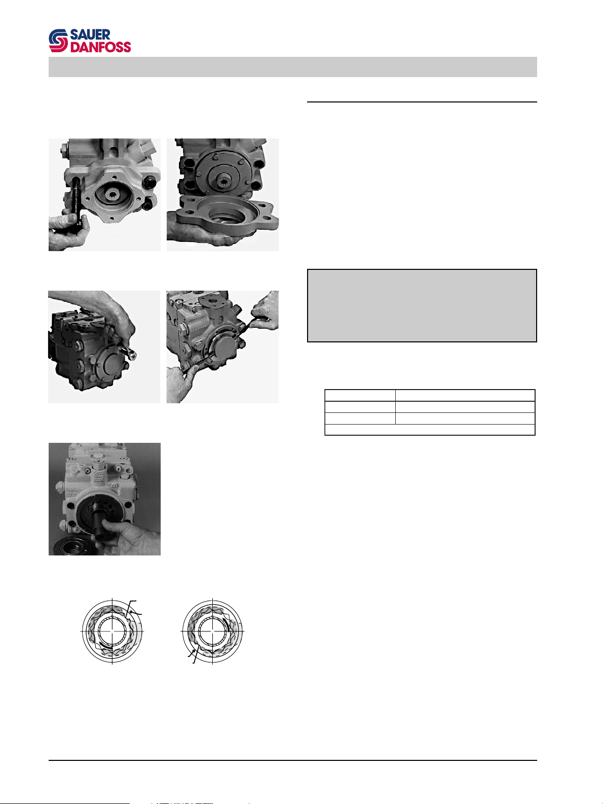
Series 90 Minor Repair Instructions
Charge Pump - Remove
The following procedure shows how to remove and install
a charge pump.
1. For pumps with an auxiliary mounting pad, remove
the four screws holding the pad to the end cap and
remove the pad. Refer to the Auxiliary Mounting Pad
Installation instructions (next section) for details.
Note: At earlier production frame size 75 pumps with
twin ports secure the end cap to the pump
housing with a clamp to avoid gasket damage.
Remove Auxiliary Pad
90000281
Adapter Screws
Remove Auxiliary Pad
Adapter
Remove Retainer Screws Remove Charge Pump Cover
Remove Drive Coupling
90000297
90000303
9000028490000282
Caution
Do not allow the force of the cylinder block spring
and swashplate leveler springs to separate the end
cap from the pump housing. Gasket damage and
external leakage may result.
S000 019E
2. Remove the six screws holding the charge pump
cover retainer.
eziSemarFeziShcnerW
001-030mm01
052-031mm31
E782200T
3. Remove the retainer and the charge pump cover. For
pumps with an auxiliary mounting pad, remove the
auxiliary drive coupling. Note the orientation of the
gerotor.
4. Remove the charge pump shaft and charge pump
drive key.
5. Remove the spacer plate(s), if present (intermediate
production pumps only).
Remove the charge pump outer port plate, if present
(early and intermediate production pumps).
Discharge
(Outside looking into pump)
58
Gerotor
Assembly
Left Hand Rotation
Orienting Alignment Pin
Alignment Pin
Inlet
Alignment Pin
Gerotor Assembly
Discharge
Right Hand Rotation
(Outside looking into pump)
Inlet
90000871E
Remove the charge pump gerotor assembly.
6. Remove the outer eccentric ring and alignment pin.
7. Remove the inner port plate.
8. Inspect all parts for abnormal wear or damage.
Page 59

Series 90 Minor Repair Instructions
Note: If a different displacement charge pump is be-
ing installed, the gerotor assembly, gerotor outer
eccentric ring, and inner port plate (early and
late production pumps) or outer spacer plate(s)
(intermediate production pumps) must be replaced together. If different thickness port plates
are used in an early production charge pump
assembly, the thicker plate is the inner port
plate (installed next to the pump end cap).
Cover
O-ring
Standard End Cap Screws
Charge Pump Assembly
Thin Port Plate
Key
Shaft
Alignment Pin
Thick Port Plate
Eccentric Ring
Gerotor Assembly
Each charge pump assembly includes a different quantity / types of port plates and spacer plates.
The charge pump kit "No Charge Pump" includes a
spacer.
Journal Bearing
Cover Retainer
Retainer Screw
Charge Pump Components (Early Production)
Standard End Cap Screw
Alignment Pin
Thin Port Plate
Charge Pump Assembly
Eccentric Ring
Gerotor Assembly
Cover
Key
Shaft
O-ring
Journal Bearing
Cover Retainer
Retainer Screw
Thin Port Plate
Spacer Plate(s)
Charge Pump Components (Intermediate Production)
Standard End Cap Screw
Alignment Pin
Charge Pump Assembly
Key
Cover
Shaft
O-ring
Gerotor Assembly
Port Plate
Eccentric Ring
90000872E
90000873E
Journal Bearing
Cover Retainer
Retainer Screw
Charge Pump Components (Late Production)
Standard End Cap Screw
Spacer
Shaft
O-ring
Cover
Plug
Journal Bearing
Cover Retainer
Retainer Screw
"No Charge Pump" Components
90000874E
90000875E
59
Page 60

Series 90 Minor Repair Instructions
Discharge
Left Hand Rotation
(Outside looking into pump)
Gerotor
Assembly
Orienting Alignment Pin
Discharge
Alignment Pin
Inlet
Alignment Pin
Gerotor Assembly
Inlet
Right Hand Rotation
(Outside looking into pump)
90000871E
Installing the Charge Pump
Be sure to install the charge pump in the proper orientation. If unsure of charge pump rotation, refer to the model
code.
Note: The charge pump rotation is determined by the
orientation of the gerotor assembly outer eccentric ring and the location of the alignment pin
in the end cap.
Do not mix charge pump piece parts from different production periods. Always install as a complete assembly.
1. Install the inner port plate and the gerotor assembly
outer ring.
2. Install the alignment pin to properly orient the port
plates and outer eccentric ring for corresponding
pump rotation.
3. Prior to installation, apply a small quantity of petroleum jelly to the I.D., O.D., and side faces of the
gerotor assembly to provide initial lubrication.
4. Install the gerotor assembly.
Install Inner Port Plate
Install Alignment Pin
Install Gerotor Assembly
Outer Ring
Install Gerotor Assembly
9000028690000285
9000028890000287
5. Install the outer port plate (early production and
intermediate production pumps only).
6. Install the spacer plate, if present (intermediate
production pumps).
7. Install the charge pump drive key into the charge
pump shaft and retain with petroleum jelly.
Install Outer Port Plate
(Early and intermediate
production only)
60
Install Spacer Plate
(Intermediate production
only)
9000029090000289
Page 61

Series 90 Minor Repair Instructions
Note: Intermediate production 75 cc and 100 cc pumps
use the same charge pump drive shaft. Two
keyways are provided in the drive shaft for the
charge pumps used in these units. The rear
keyway (with identifier groove) is used in 75 cc
pumps. The front keyway (closest to the internally splined end of the shaft) is used in 100 cc
pumps.
8. Install the charge pump shaft. The internally splined
end of the shaft must engage the main pump shaft.
Note: The outside diameter of the internally splined
end of some early production charge pump
shafts was chamfered. Early production end
caps may not be machined to accept a nonchamfered shaft. Always use a chamfered
charge pump shaft in pumps with the early end
cap.
9. For pumps with an auxiliary mounting pad, install the
auxiliary drive coupling.
10. Install a new O-ring onto the non-auxiliary pad charge
pump cover. (If an auxiliary pad is installed, an O-ring
is not used on the cover.)
100 cc
Keyways in Charge Pump
Shaft (Intermediate Produc-
tion 075 and 100)
75 cc
90000291 90000292
Install Charge Pump Shaft
11. Carefully remove the alignment pin from the charge
pump parts. Install the pin in its hole in the charge
pump cover (see previous page for correct orientation) and retain with petroleum jelly. Install the cover
(with alignment pin) into the end cap and aligned
charge pump parts. (Take care not to damage the
cover O-ring, if used.)
Caution
In order to avoid loss of charge pressure in pumps
with an auxiliary mounting pad, always install the
charge pump cover with the pad drain hole located
on the same side of the end cap as the charge inlet
port. Refer to the section „Auxiliary Pad Installation“
for details.
S000 020E
12. Install the charge pump cover retainer and the six hex
screws and torque the screws.
eziSemarFeuqroT
001-030)tf•fbl01(mN5.31
052-031)tf•fbl42(mN23
E882200T
Alignment Pin Installed in
Cover
90000293
Install Charge Pump Cover
90000294
13. For pumps with auxiliary mounting pads, install the
O-ring and auxiliary mounting pad adaptor onto the
end cap. Refer to the corresponding section for
instructions on auxiliary pad installation.
90000283 90000295
Torque Retainer ScrewsInstall Cover Retainer
61
Page 62

Series 90 Minor Repair Instructions
Auxiliary Pad Installation
1. Remove the six screws holding the charge pump
cover retainer. Remove the retainer.
eziSemarFeziShcnerW
001-030mm01
052-031mm31
2. Remove the charge pump cover and its O-ring.
Note: The original charge pump cover will not be used
when installing the auxiliary pad.
Remove Screws and
Retainer
Remove Charge Pump Cover
9000028490000282
3. Remove the four large screws which fasten the end
cap to the pump housing.
eziSemarFseziShcnerW
xeHlanretnIxeHlanretxE
-030
240ylrae
240etalmm01
550mm91
001-570mm42
031-001mm41
052-081mm71
mm8
E782200T
E982200T
Screw
Remove Large End Cap Screws
Charge Pump Parts
Cover
Assembly
Special Washer
End Cap
Screw
O-ring
Pad Cover
O-ring
auxiliary Pad
(Typical)
Auxiliary Pad Kit
Auxiliary Pad Components (Typical)
Coupling
(Typical)
Journal Bearing
Cover Retainer
Retainer Screw
90000296
90000876E
Note: At earlier production frame size 75 pumps with
twin ports secure the end cap to the pump
housing with a clamp to avoid gasket damage.
Caution
Do not allow the force of the cylinder block spring
and swashplate leveler springs to separate the end
cap from the pump housing. Gasket damage and
external leakage may result.
S000 019E
4. Take care to assure the surfaces are clean and free
of any foreign material or paint prior to installing the
auxiliary pad.
5. Install the auxiliary drive coupling onto the pump
drive shaft spline (auxiliary drive spline must be
toward the rear of the pump).
62
Page 63

Series 90 Minor Repair Instructions
6. Carefully remove the alignment pin from the charge
pump parts. Install the pin in its hole in the new
charge pump cover (with hole for the auxiliary coupling) and retain with petroleum jelly. Install the new
charge pump cover with alignment pin into the end
cap and the aligned charge pump parts.
Caution
In order to avoid loss of charge pressure in pumps
with an auxiliary mounting pad, always install the
charge pump cover with the pad drain hole located on the same side of the end cap as the
charge inlet port. Refer to the section "Auxiliary
Pad Installation" for details.
7. Install the charge pump cover retainer and the six hex
screws and torque the screws.
eziSemarFeuqroT
001-030)tf•fbl01(mN5.31
052-031)tf•fbl42(mN23
8. Install O-ring on end cap pilot.
S000 020E
Install Drive Coupling Install Alignment Pin in
Cover (CCW rotation shown)
E882200T
9000029890000297
9. Install the auxiliary mounting pad adapter on external
pilot on rear of end cap.
10. Install four new large screws and washers through
the mounting pad and end cap into the housing.
Torque per the accompanying table.
eziSemarFeuqroT
-030
240ylrae
240etal)tf•fbl09(mN221
550)tf•fbl09(mN221
001-570)tf•fbl981(mN652
031-001)tf•fbl022(mN892
052-081)tf•fbl924(mN085
)tf•fbl34(mN85
E092200T
11. Install the O-ring and flange cover or auxiliary pump.
Auxiliary Pad Conversion
To convert an auxiliary mounting pad to a different size
mounting pad, use the above procedure with the following
additions:
After removing the charge pump cover (step 2), remove
the old auxiliary drive coupling.
Install New Charge Pump
Cover
Install O-ring on End Cap
Pilot
90000299
Install Screws and Cover
Retainer
Install Auxiliary Pad Adapter
90000300
9000030390000302
After removing the four end cap retaining screws, remove
the old auxiliary mounting pad adapter.
Install Auxiliary Pad Adapter
Screws
90000281
Torque Pad Adapter Screws
90000305
63
Page 64

Series 90 Minor Repair
Filtration Options
Suction Filtration Installation
1. Install the hydraulic fitting to connect the external
suction filter to the charge pump inlet port.
2. The reducer fitting (placed on the charge pressure
gauge port) is installed as follows.
eziSemarFeziShcnerWeuqroT
240-030hcni4/1-1)tf•fbl25(mN07
031-550hcni2/1-1)tf•fbl09(mN221
052-081hcni2/1-1)tf•fbl511(mN651
Charge Pump Inlet Reducer Fitting and
Gauge Port Plug
9000024390000310
The gauge port plug takes a 1/4 inch internal hex
wrench and is torqued to 27 Nm (20 lbf•ft).
Remote Charge Pressure Filtration or Integral Charge
Pressure Filtration
Install either of these two filtration devices as follows.
1. Remove the reducer fitting, located at charge pressure gauge port, from pump end cap (this part will not
be used).
E192200T
90000311 90000314
Manifold
Install Remote Pressure
Filter Manifold
Integral Pressure Filter Headremote Pressure Filter
Install Integral Pressure
Filter Head
2. Install the filter manifold or filter head into the port.
The hydraulic tube should enter its mating bore in the
pump end cap with a low force.
3. After rotating the filter manifold or filter head clockwise so that the threads engage with the threads in
the end cap, continue to rotate it clockwise between
6 and 7 revolutions. Face manifold or head to the
desired position.
Caution
Failure to install the filter manifold or filter head to a
sufficient depth in the end cap will result in insufficient
engagement of the tube in the end cap bore. This may
allow unfiltered oil to bypass the filter and enter the
9000031590000312
charge system.
S000 021E
4. While holding the filter manifold or filter head in the
desired position, tighten the swivel lock nut.
eziSemarFeziShcnerWeuqroT
240-030hcni8/3-1)tf•fbl25(mN07
031-550hcni8/5-1)tf•fbl09(mN221
052-081hcni8/5-1)tf•fbl511(mN651
E292200T
Tighten Remote Pressure
Filter Manifold Lock Nut
64
90000313 90000316
Tighten Integral Pressure
Filter Head Lock Nut
5. After installing the integral pressure filter head assembly, install the filter canister per the instructions
on the filter canister.
Page 65

Series 90 Minor Repair
Pump controls
Cover Plate
1. Thoroughly clean external surfaces prior to removal
of cover plate.
2. Using a 5 mm internal hex wrench, remove the eight
cover plate mounting screws. Remove the cover
plate and gasket from housing.
Caution
Protect exposed surfaces and cavities from damage
and foreign material.
S000 022E
3. In preparation for installing the cover plate, place a
new gasket on the housing. Place the cover plate into
position and install the screws. Torque the screws to
16 Nm (12 lbf•ft).
NOTE
A sealing washer must be installed under the head of
any mounting screws that are installed into "thru"
holes in the housing.
S000 023E
Pump with Cover Plate
90000361
65
Page 66
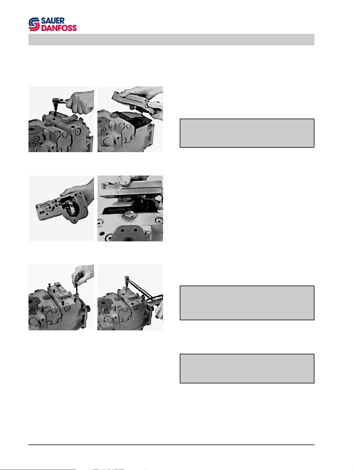
Series 90 Minor Repair
Manual Displacement Control (MDC)
1. Thoroughly clean external surfaces prior to removal
of control.
2. Using a 5 mm internal hex wrench, remove the eight
control mounting screws. Remove the control (with
orifice check valve and spring) and control gasket
from housing.
Caution
Protect exposed surfaces and cavities from damage
and foreign material.
S000 022E
Remove Mounting Screws Remove Control
Inner Face of Control Assemble Control to Linkage
9000032090000319
9000032290000321
3. In preparation for installing the control, place a new
gasket on the housing. Inspect to assure that the
control orifice check valve and spring are in their
proper position in the control.
4. While setting the control into position, engage the pin
on the control linkage into the mating hole in the link
attached to the swashplate.
5. With the control in position, move control lever both
directions to check proper engagement of control
linkage pin. Proper engagement will be indicated by
centering torque as the lever is moved from center.
Non-engagement of control linkage pin is indicated
by lack of centering torque as the lever is moved. In
case of non-engagement remove the control and
repeat the above procedure.
6. Align the control gasket and install the screws. Torque
the screws to 16 Nm (12 lbf•ft).
NOTE
A sealing washer must be installed under the head of
any mounting screws that are installed into "thru"
holes in the housing.
S000 023E
Assemble Control to
Pump
66
Torque Mounting Screws
9000032490000323
7. If the control is equipped with a neutral start switch,
refer to the "MDC Neutral Start Switch Adjustment"
instructions.
WARNING
The neutral start switch "neutral" must be readjusted after reassembling the MDC module.
S000 024E
Page 67

Series 90 Minor Repair
Solenoid Override Valve for MDC
1. Thoroughly clean external surfaces prior to removal
of valve.
2. Using a 5 mm internal hex wrench, remove the two
screws and remove solenoid manifold from housing.
Remove the old gasket.
3. The solenoid may be removed from the valve by
removing the nut with a 3/4 inch hex wrench. The
solenoid valve may be removed from the manifold
with a 7/8 inch hex wrench.
4. When installing the solenoid valve into the manifold,
the valve should be torqued to 24 ± 2.4 Nm (17.7 ± 1.8
lbf•ft). When installing the solenoid onto the valve,
torque the nut to 6 Nm (53 ± 12 lbf•in).
5. In preparation for installing the solenoid manifold,
place a new gasket on the control housing. Install the
manifold onto the control housing, align the gasket,
and install the screws. Torque the screws to
13.5 Nm (10 lbf•ft).
Components of Solenoid Override for MDC
90000363
Solenoid Override Valve for MDC with Pressure
Released Brake
1. Thoroughly clean external surfaces prior to removal
of valve.
2. Using a 4 mm internal hex wrench, remove the four
solenoid valve mounting screws. Remove the solenoid valve (with O-rings) from the adapter plate.
3. Using a 4 mm internal hex wrench, remove the four
adapter plate mounting screws. Remove the adapter
plate and O-rings from the control housing.
4. Remove the check valve seat and O-ring from the
control side of the adapter plate. Remove the check
ball and spring.
5. Install a new O-ring on the check valve seat and
reassemble the check valve spring, ball, and seat
into the adapter plate.
6. Install new O-rings on the adapter plate. Place the
adapter plate into position and install the screws.
Torque the screws to 5.4 Nm (48 lbf•in).
7. Install new O-rings onto the solenoid valve assembly
and install the solenoid valve onto the adapter plate.
Install the screws and torque to 5.4 Nm (48 lbf•in).
Components of Solenoid Override with Brake Pressure
90000364
Defeat for MDC
67
Page 68

Series 90 Minor Repair
Hydraulic and Electric Displacement Controls
1. Thoroughly clean external surfaces prior to removal
of control.
2. Using a 5 mm internal hex wrench, remove the eight
control mounting screws. Remove the control (with
orifice check valve and spring) and control gasket
from housing.
Caution
Protect exposed surfaces and cavities from damage
and foreign material.
S000 022E
Remove Mounting Screws Remove Control
Inner Face of Control Assemble Control to Linkage
Install Mounting Screws Torque Mounting Screws
9000032690000325
9000032890000327
9000033090000329
3. In preparation for installing the control, place a new
gasket on the housing. Inspect to ensure that the
control orifice check valve and spring are in their
proper position in the control.
4. While setting the control into position, engage the pin
on the control linkage into the mating hole in the link
attached to the swashplate.
5. With the control in position, move control assembly
left and right to check engagement of pin in the link.
Proper engagement will be indicated by an increasing resistance as the control is moved away from
center position. Non-engagement of pin will be indicated by lack of spring force. In case of non-engagement, remove control and repeat the above procedure.
6. Align the control gasket and install the screws. Torque
the screws to 16 Nm (12 lbf•ft).
Caution
A sealing washer must be installed under the
head of any mounting screws that are installed
into "thru" holes in the housing.
S000 023E
Pressure Control Pilot (PCP) for Electric Displacement Control
1. Thoroughly clean external surfaces of control.
PCP Components Torque PCP Valve Screws
68
2. Using a 4 mm internal hex wrench, remove the four
screws and remove the PCP.
3. Check surfaces for nicks or damage. Clean internal
screens.
4. Install new O-rings in PCP Housing. Place PCP
against EDC housing and install the screws. Torque
to 5.4 Nm (48 lbf•in).
9000033490000332
Note: Do not remove black plastic cover from the
aluminum plate. This is not a serviceable item
and will void the product warranty.
Page 69

Series 90 Minor Repair
3-Position (FNR) Electric Control
1. Thoroughly clean external surfaces prior to removal
of control.
2. Using a 4 mm internal hex wrench, remove the four
solenoid valve mounting screws. Remove the solenoid valve (with O-rings and orifice) from the adapter
plate.
3. Using a 5 mm internal hex wrench, remove the eight
adapter plate mounting screws. Remove the adapter
plate and gasket from housing.
Caution
Protect exposed surfaces and cavities from damage
and foreign material.
S000 022E
4. Inspect the orifice installed between the valve and
adapter plate. This orifice MUST be installed in the
case drain passage for proper pressure limiter operation.
5. In preparation for installing the adapter plate, place a
new gasket on the housing. Place the adapter plate
into position and install the screws. Torque the
screws to 16 Nm (12 lbf•ft).
NOTE
A sealing washer must be installed under the head of
any mounting screws that are installed into „thru“
holes in the housing.
S000 023E
6. Install new O-rings and the orifice onto the solenoid
valve assembly and install the solenoid valve onto
the adapter plate. Install the screws and torque to
5.4 Nm (48 lbf•in).
Displacement Control Components
3-Position Electric Control Components
90000362
Displacement Control Orifices
1. Remove the control assembly as described in the
instructions for the specific displacement control.
2. Orifice plugs may be located in the control assembly,
at the pump housing face surface. Remove the
orifice plugs with a 4 mm internal hex wrench. Note
the location of each plug, do not interchange plugs.
Torque the orifice plugs to 3 Nm (26 lbf•in).
3. Assemble the control onto the pump. Refer to the
instructions for the specific control.
A
B
TA
P
TB
Orifice Plugs
Orifice Check Valve
Underside of an HDC/EDC Module Showing Orifice
Locations
90000849E
69
Page 70

Series 90 Minor Repair
Displacement Control Orifice Check Valve
1. Remove the control assembly as described in the
instructions for the specific displacement control.
2. The orifice check valve is located in the control
B
TA
A
Orifice Plugs
Orifice check Valve
Underside of an MDC Module Showing Orifice Locations
TB
P
90000848E
assembly, at the surface of the pump housing face.
Remove the spring retainer and spring from the
orifice check valve cavity and then remove the orifice
check valve.
3. Install the desired orifice check valve in the cavity and
then install the spring and spring retainer to hold the
orifice check valve in position.
4. Assemble the control onto the pump. Refer to the
instructions for the specific control.
Displacement Control Adapter Plate (Early production 130 Pumps only)
Displacement Control Adapter Plate (Early production
90000847
130cc Pumps only)
The screws fastening the control adapter plate to the
housing have retaining compound on the threads. They
are removed with a 6 mm internal hex wrench.
When installing the adapter plate, ensure the O-rings are
in the proper position and torque the screws to 32 Nm
(24 lbf•ft).
Displacement Control Filter Screens
If the pump is equipped with control filter screens in the
pump housing (late production), they should be pressed
into position (with the rounded edge of the filter screens
facing the control until they are flush to 2.0 mm (0.08 inch)
below the surface of the housing.
70
Page 71

Series 90 Minor Repair
Minor Repair - Motor
Loop Flushing and Charge Relief Valves
Loop Flushing Valve
1. Using an 1-1/16 inch wrench, remove the hex plugs
and O-rings from both sides of the valve. Remove the
springs, shoulder washers, and flushing valve shuttle
spool. Note orientation of the washers. Remove the
flushing valve spool.
2. Inspect parts for damage or foreign material.
Note: Early production motors used a small diameter
shuttle valve spool. Late production motors use
a larger diameter spool.
3. Install flushing valve spool in end cap, then install the
shoulder washers (with shoulders facing “out”) and
springs on each end of the spool. Install the hex plugs
with O-rings, and torque to 41 Nm (30 lbf•ft) on 030
through 100 motors or 68 Nm (50 lbf•ft) on 130
motors.
Motor Charge Relief Valve
1. Remove the shim adjustable charge relief valve plug
with a 7/8 inch hex wrench.
Before removing the screw adjustable relief valve
plug, mark the plug, lock nut, and housing so as to be
able to maintain the original adjustment when assembling. Remove the screw adjustable charge relief
valve plug by loosening the lock nut with a 1-1/16 inch
hex wrench for 030 through 100 units, or a 1-5/8 inch
hex wrench for 130 units, and unscrewing the plug
with a large screwdriver or 1/2 inch hex wrench.
2. Remove the spring and valve poppet.
Remove Plugs Springs
Install Flushing Shuttle
Spool
Remove Flushing Shuttle
Spool
Torque Plugs
9000033990000338
9000034190000340
3. Inspect the poppet and mating seat in the end cap for
damage or foreign material. When inspecting shim
adjustable valves, do not alter the shims or interchange parts with another valve.
Remove Shim Charge Relief
Valve
Remove Screw Charge Relief
Valve
9000034390000342
71
Page 72

Series 90 Minor Repair
4. Install the poppet and spring. For shim adjustable
valves, install the plug and torque to 68 Nm (50 lbf•ft).
For screw adjustable valves, install the plug with its
lock nut, aligning the marks made at disassembly,
and torque the lock nut to 52 Nm (38 lbf•ft).
5. Check and adjust the charge pressure.
Shim Adjustable Charge
Relief Valve
Lock Nut
Plug
O-ring
Spring
Poppet
Plug with O-ring
(defeat)
Plug
O-ring
Spring
Shoulder Washer
Screw Adjustable Charge
9000034590000344
Relief Valve
Plug
O-ring
Shims
Spring
Poppet
Plug with O-ring
(defeat)
Spool (defeat)
Plug with O-ring
(defeat)
Defeating the Loop Flushing Valve
1. Remove loop flushing valve components (these parts
will not be used).
2. Install defeating spool into spool bore in end cap.
3. Install hex plugs provided and torque to 41 Nm
(30 lbf•ft).
4. Remove charge relief valve components (these parts
are not necessary).
5. Replace with the hex plug provided and torque to
41 Nm (30 lbf•ft).
Note orientation of washers!
Shoulder OUT (toward spring).
Spool
Shoulder Washer
Spring
O-ring
Plug
90000850E
Motor charge Relief Valve and Loop Flushing Valve Parts
72
Page 73

Series 90 Minor Repair
Minimum Displacement
Limiter Screw
Seal Lock Nut
Tamper-Resistant Cap
Seal Lock Nut
Maximum Displacement
Limiter Screw
Tamper-Resistant Cap
SAE Flange Version shown
(cartridge Version similar)
Variable Motor Displacement Limiters
1. Remove the tamper-resistant cap from the displacement limiter. Measure and note the length of the
adjustment screw up to the seal lock nut. Using a
19 mm hex wrench, loosen the seal lock nut and
remove the nut. Remove the limiter screw from the
motor housing with a 6 mm internal hex wrench.
2. Install the limiter screw with the noted length between
adjustment screw and the seal lock nut. Do not install
a new tamper-resistant cap until the limiter has been
adjusted.
3. Final adjustment of the displacement limiters should
be performed on a test stand.
Do not turn the limiter screws counterclockwise
beyond their initial adjustment positions.
Caution
Care should be taken in adjusting displacement
limiters to avoid undesirable speed conditions. The
seal lock nut must be retorqued after every
adjustment to prevent an unexpected change in
operating conditions and to prevent external leakage
during unit operation.
S000 026E
4. Following the final adjustment, install new tamper
One full turn of the displacement limiter adjustment
screw will change the displacement as follows:
eziSemarF
550mc6.5
570mc1.7
3
3
3
ni43.0(veR/
3
ni34.0(veR/
wercSgnitsujdA
foveRreppsiDniegnahCxorppA
)veR/
)veR/
E592200T
resistant caps.
MV Displacement Limiters
90000851E
73
Page 74

Series 90 Minor Repair
Variable Motor Controls
Electrohydraulic 2-Position Control (Types
NA, NB, NC, and ND)
1. Thoroughly clean external surfaces prior to removal
of the control.
2. Disconnect the external electrical signal connection.
Remove BEFORE removing control.
Note:
Hydraulic 2-Position
Control Valve
Install AFTER installing control.
Refer to "Control Orifices" Section
3. Remove the hex nut and solenoid from the control
valve.
4. Remove the orifice check valve for the maximum
angle control cylinder, if equipped.
5. Remove the control valve from the motor housing.
6. Remove O-rings from the valve.
Electric 2-Position
Control Valve
MV Control components
1/8 in. int. hex wrench
Torque: 5.4 Nm (48 lbf•in)
9/16 in. hex wrench
Torque: 34 Nm (25 lbf•ft)
7/8 in. hex wrench
Torque: 68 Nm (50 lbf•ft)
90000852E
7. Install new O-rings on the control valve.
8. Install the valve into the motor housing and torque to
47 Nm (35 lbf•ft). Do not overtorque the control
valve. Over-torquing may result in the valve spool
sticking.
9. Install the solenoid onto the valve and torque the hex
nut to 5 Nm (44 lbf•in). Do not overtorque the nut.
10. If previously removed, reinstall the orifice check
valve. Reconnect the external signal connection.
Hydraulic 2-Position Control (Type PT)
Follow the steps above, except that in step 2 a hydraulic
signal line will be disconnected, and steps 3 and 9 are not
applicable.
Control Plugs
Remove the control plugs from the housings of earlier
production motors, if necessary. Install new O-rings,
reinstall, and torque.
74
MV Control Plugs
90000853E
Page 75

Series 90 Minor Repair
Variable Motor Control Orifices
Control Supply Orifice
1. Remove the control supply orifice from the motor
housing with an 1-1/16 inch hex wrench.
2. Remove the O-rings and the backup washers. Check
that the filter screen is secure in the orifice body and
that the screen and the orifice are not plugged.
Backup Washer
Control Suply Orifice
Screen (pressed in)
O-ring
Backup Washer
O-ring
3. Install new backup washers and O-rings onto the
orifice body. Install the orifice into the motor housing
and torque to 37 Nm (27 lbf•ft).
Caution
Do not interchange the control supply orifice with the
minimum displacement orifice (next section).
S000 027E
Minimum Displacement Cylinder Orifice or Orifice
Check Valve
1. Remove the minimum displacement cylinder drain
orifice or the orifice check valve from the motor
housing with an 1-1/16 inch hex wrench.
2. Remove the O-rings and the backup washers. Check
that the orifice is not plugged. Check that the check
valve seat is secure in the body and that the check
ball is free.
Backup Washer
Screen
(pressed in)
Orifice
O-ring
Backup Washer
Orifice Body
Cross-section View of
Control Supply Orifice Assembly
MV Control Supply Orifice
Orifice / Check Valve
Assembly
O-ring
Backup Washer
O-ring
Backup Washer
O-ring
90000854E
3. Install new backup washers and O-rings onto the
orifice body. Install the orifice into the motor housing
and torque to 37 Nm (27 lbf•ft).
Caution
Do not interchange the control supply orifice (previous
section) with the minimum displacement orifice.
S000 028E
O-ring
Orifice Body
Backup Washer
O-ring
Backup Washer
Cross-Section View of
Orifice Assembly
Spring Pin
Kugel
MV Minimum Displacement Orifice
O-ring
Orifice Body
Backup Washer
O-ring
Backup Washer
Orifice Seat
(Spot welded)
Cross-Section View of
Orifice / Check Valve
Assembly
90000855E
75
Page 76

Series 90 Minor Repair
Maximum Displacement Cylinder Orifice Check Valve
1. Remove the seal lock nut with a 3/4 inch hex wrench.
Housing Plug
Orifice / Check Valve Assembly
Seal Lock Nut
(seal toward housing)
O-ring
Orifice Body
Check Ball
Spring Pin
Cross-Section View of
Orifice / Check Valve
Assembly
Seal Lock Nut
(seal toward housing)
O-ring
Remove the maximum displacement cylinder orifice
check valve from the motor housing with a 1/4 inch
end wrench. Remove the O-ring. The check ball in
the valve must be free.
2. Reinstall the check valve and torque to 15 Nm
(11 lbf•ft). Install a new O-ring. Install the seal lock
nut with the seal toward the motor housing.
Hold the check valve from turning while torquing
the seal lock nut to 34 Nm (25 lbf•ft).
3. If no orifice check valve is installed, the housing plug
may be removed with a 9/16 inch hex wrench. Always
install a new O-ring. Reinstall the plug and torque to
20 Nm (15 lbf•ft).
MV Maximum Displacement Orifice
90000856E
76
Page 77

Series 90 Minor Repair
Speed Sensor
1. Remove the speed sensor by disconnecting the
electrical connector, loosening the lock nut, and
unscrewing the speed sensor from the pump or
motor housing.
2. Always install a new O-ring before installing the
sensor.
3. Reinstall the speed sensor (with lock nut and O-ring)
into the housing. Adjust the gap between the sensor
and the magnetic speed ring as instructed in Section
"Speed Sensor Adjustment" and torque the sensor
lock nut.
4. If a speed sensor is not installed, the housing plug
should be torqued as indicated in the accompanying
figure.
Speed Sensor
or
1-1/16 in. hex wrench
Torque: 13 Nm (10 lbf•ft)
After adjustment!
Typical Location of Speed Sensor - PV
1-1/16 in. hex wrench
Torque: 13 Nm (10 lbf•ft)
Housing Plug
1/4 in. int. hex wrench
Torque: 23 Nm (17 lbf•ft)
After adjustment!
90000857E
Housing Plug
1/4 in. int. hex wrench
Torque: 23 Nm (17 lbf•ft)
Typical Location of Speed Sensor - MF
1-1/16 in. hex wrench
Torque: 13 Nm (10 lbf•ft)
After adjustment!
Speed Sensor
or
Typical Location of Speed Sensor - MV
or
Speed Sensor
Housing Plug
1-1/16 in. hex wrench
Torque: 37 Nm (27 lbf•ft)
90000858E
90000859E
77
Page 78

Series 90 Exploded View Parts Drawings / Parts Lists
Exploded View Parts Drawings / Parts Lists
Variable Pumps
Minor Repair Parts
B83
P30
P30
P2A_
OR
P2B_
P06
B83
P13
B82
P06
G542
G546
P13
G522
G526
(G63)
(G64)
G532
G536
B70
B80
BOTH SIDES
OR
K90
K10
K50
K70
K80
(B90)
G63
(CODE 61 OPTION)
G64
(CODE 61 OPTION)
K018
bis
K042
(G502
G506)
G541
G548
(B70)
L35
(Early Production
075 Frame Size)
(B80)
B90
(G502
G506)
G531
G538
G512
G516
G502
G506
(L40)
B71
G172
G176
L50
L30
(K018
THRU
K042)
(L70)
L60
L40
G501
G508
G511
G518
G63
(CODE 61 OPTION)
L70
78
G521
G528
(G501
G508)
(G501
G508)
(G63)
(G64)
G64
(CODE 61 OPTION)
90000860E
Page 79

Series 90 Exploded View Parts Drawings / Parts Lists
Parts List
Item Description Qty Item Description Qty
B70 ............... Plug ......................................................... 2
B71 ............... Plug ......................................................... 1
B80 ............... Plug ......................................................... 1
B82 ............... Plug ......................................................... 1
B90 ............... Filter screen ............................................ 3
G63 .............. Split flange clamp .................................... 4
G64 .............. Plug ......................................................... 4
G172 ............ Plug ......................................................... 1
G176 ............ O-ring ...................................................... 1
G501 ............ Plug ......................................................... 3
G502 ............ Plug ......................................................... 3
G506 ............ O-ring ...................................................... 3
G508 ............ O-ring ...................................................... 3
G511 ............ Plug ......................................................... 1
G512 ............ Plug ......................................................... 1
G516 ............ O-ring ...................................................... 1
G518 ............ O-ring ...................................................... 1
G521 ............ Plug ......................................................... 1
G522 ............ Plug ......................................................... 1
G526 ............ O-ring ...................................................... 1
G528 ............ O-ring ...................................................... 1
G531 ............ Plug ......................................................... 1
G532 ............ Plug ......................................................... 1
G536 ............ O-ring ...................................................... 1
G538 ............ O-ring ...................................................... 1
G541 ............ Plug ......................................................... 1
G542 ............ Plug ......................................................... 1
G546 ............ O-ring ...................................................... 1
G548 ............ O-ring ...................................................... 1
K10 ............... Plug assembly ......................................... 1
K50 ............... O-ring ...................................................... 1
K70 ............... Spring ...................................................... 1
K80 ............... Poppet .....................................................1
K90 ............... Nut ........................................................... 1
L30 ............... Seal carrier .............................................. 1
L35 ............... Seal carrier .............................................. 1
L40 ............... Lip seal .................................................... 1
L50 ............... O-ring ...................................................... 1
L60 ............... Retainer ................................................... 1
L70 ............... Screw ...................................................... 3
L8 ................. Key .......................................................... 1
L9 ................. Slotted nut ............................................... 1
79
Page 80

Series 90 Exploded View Parts Drawings / Parts Lists
Variable Pump Controls
M95M
M96M
T001
THRU
T009,
T022
T050
M97M
M9ME
T201
THRU
T209,
T222
T250
T301
THRU
T309,
T322
T350
M98M
T401
THRU
T409,
T422
T450
M76M
M92M
M77M
M1MA
M1MB
M1MC
M1MD
M1ME
M1MF
M1MG
M850
M0MA M0ME
M0MB M0MF
M0MC M0MG
M0MD M0M9
M90M
M880
M870
M840
M840
REF
M830
M74M
M860
M840
REF
M78M
M75M
M87M
S40
M72M
M71M
M11M
M90D
M7MA
M7MB
M7MC
M7MD
M7ME
M7MF
M7MG
M810
M820
M11D
M1DC
M1DD
M0DC
M0DD
M0EA
M0EF
M0EP
M1EA
M1EF
M1EP
M11C
M90E
M880
M11E
M1CA
M91E
M9EA
M9EP
M87E
OR
M87C
M97E
M0CA
M90C
OR
M98E
M95E
M96E
80
OR
(Early Production
130 cc Frame Size)
M1HA, M1HC
M1HF, M1HG
M1HH, M1HJ
M1HK, M1HL
M1HM, M1HN
M11H
M90H
M880
M87H
M0HA, M0HC
M0HF, M0HG
M0HH, M0HJ
M0HK, M0HL
M0HM, M0HN
OR
90000861E
Page 81

Series 90 Exploded View Parts Drawings / Parts Lists
Control Parts List
Item Description Qty Item Description Qty
M0CA ........... Cover plate kit ......................................... 1
M1CA ........... Cover plate .............................................. 1
M11C ........... Control gasket ......................................... 1
M11D ........... Control gasket ......................................... 1
M87C ........... Washer, seal (042) ................................. 1
M90C ........... Screw ...................................................... 6
M0DC ........... Control kit, 3-position FNR 12V .............. 1
M0DD ........... Control kit, 3-position FNR 24V .............. 1
M1DC ........... Control, 3-position FNR 12V ................... 1
M1DD ........... Control, 3-position FNR 24V ................... 1
M80 .............. Control gasket ......................................... 1
M87D ........... Washer, seal (042) ................................. 1
M90D ........... Screw ...................................................... 6
M0EA ........... Control kit, EDC with
MS connector .......................................... 1
M0EP ........... Control kit, EDC with
Packard connector .................................. 1
M1EA ........... Control, EDC with
MS-connector .......................................... 1
M1EP ........... Control, EDC with
Packard-connector .................................. 1
M9EA ........... PCP type 3 oil filled (MS) ........................ 1
M9EA ........... PCP type 3 oil filled (Packard) ................ 1
M80 .............. Control gasket ......................................... 1
M87E ............ Washer, seal (042) ................................. 1
M90E ............ Screw ...................................................... 6
M91E ............ Plastic cap (MS) ......................................1
M95E ............ O-ring ...................................................... 2
M96E ............ O-ring ...................................................... 1
M97E ............ O-ring ...................................................... 1
M98E ............ Screw ...................................................... 4
M1MA........... Servovalve kit .......................................... 1
M0HA ........... Control kit, hydraulic, HDC ..................... 1
M0HC ........... Control kit, hydraulic, HDC ..................... 1
M1HA ........... Control, hydraulic, HDC .......................... 1
M1HC ........... Control, hydraulic, HDC .......................... 1
M11H ........... Control gasket ......................................... 1
M80 .............. Control gasket ......................................... 1
M87H ........... Washer, seal (042) ................................. 1
M90H ........... Screw ...................................................... 6
M0MA........... Control MDC
w/o neutral start switch ........................... 1
M7M ............. Control handle ......................................... 1
M71M ........... Washer .................................................... 1
M72M ........... Nut ........................................................... 1
M80 .............. Control gasket ......................................... 1
M87M ........... Washer, seal (042) ................................. 1
M90M ........... Screw ...................................................... 6
S40 ............... Neutral start switch kit ............................. 1
M0MC .......... Control MDC w/ sol. valve ...................... 1
M7M .............Control handle ......................................... 1
M71M ........... Washer .................................................... 1
M72M ........... Nut ........................................................... 1
M74M ........... Solenoid valve ......................................... 1
M75M ........... Control manifold ...................................... 1
M77M ........... Manifold gasket ....................................... 1
M78M ........... Screw ...................................................... 2
M80 .............. Control gasket ......................................... 1
M87M ........... Washer, seal (042) ................................. 1
M90M ........... Screw ...................................................... 6
M0MD .......... Control MDC w/ sol. valve and
neutral start switch .................................. 1
M7M .............Control handle ......................................... 1
M71M ........... Washer .................................................... 1
M72M ........... Nut ........................................................... 1
M75M ........... Control manifold ...................................... 1
M76M ........... Solenoid valve ......................................... 1
M77M ........... Manifold gasket ....................................... 1
M78M ........... Screw ...................................................... 2
M80 .............. Control gasket ......................................... 1
M87M ........... Washer, seal (042) ................................. 1
M90M ........... Screw ...................................................... 6
S40 ............... Neutral start switch ................................. 1
M810 ............ Adapter plate - Control (130 cc) ............. 1
M820 ............ O-ring (130 cc) ........................................ 1
M830 ............ O-ring (130 cc) ........................................ 1
M840 ............ O-ring (130 cc) ........................................ 2
M850 ............ Plug (130 cc) ........................................... 1
M860 ............ Screw (130 cc) ........................................ 6
M870 ............ Plug (130 cc) ........................................... 1
M9ME........... 4/2 Way valve ......................................... 1
M92M ........... Screw ...................................................... 4
M95M ........... O-ring ...................................................... 1
M96M ........... O-ring ...................................................... 1
M97M ........... O-ring ...................................................... 1
M98M ........... Screw ...................................................... 4
T001-9 .......... Control orifice kit ..................................... 1
T201-9 .......... Orificed check valve ................................ 1
T301-9 .......... Spring ...................................................... 1
T401-9 .......... Spring retainer ......................................... 1
M0MB........... Control MDC
w/ neutral start switch ............................. 1
M7M ............. Control handle ......................................... 1
81
Page 82

Series 90 Exploded View Parts Drawings / Parts Lists
Filter and Options
N00R
H50
N10R
H50L
N35R
H50
N00M
N30R
OR
H60
N35M
REF
N20R
H30
N15R
H05
H50
N40P
N31R
N25R
H60
N35M
N20M
H40
N10M
N15M
OR
OR
H05
N25M
(H30)
N40L
H30
N35S
Or
H40
N10S
OR
H50
H60
N00S
H05
H40
90000862E
J80N
H90L
82
H80
H70
J15N
J40N
OR
J30
J95_
J80_
J92_
J70_
J90_
J00_
J60_
J15_
J50_
J10_
J30
H70
H80
90000863E
Page 83

Series 90 Exploded View Parts Drawings / Parts Lists
Parts List Filter and Options
Item Description Qty Item Description Qty
H05B-H ........ Kit - Charge pump ................................... 1
H50L ............ Spacer (No charge pump) ...................... 1
H30 .............. Port plate ................................................. 2
H40 .............. Pin ........................................................... 1
H50 .............. Charge pump shaft ................................. 1
H60 .............. Key .......................................................... 1
H70 .............. Retaining plate ........................................ 1
H80 .............. Screw ...................................................... 6
H90L ............ Plug ......................................................... 1
J00A ............. Aux. mtg. SAE A flange .......................... 1
J00B ............. Aux. mtg. SAE B flange .......................... 1
J00C ............. Aux. mtg. SAE C flange .......................... 1
J00D ............. Aux. mtg. SAE D flange .......................... 1
J00T ............. Aux. mtg. SAE A flange (11 T) ............... 1
J00V ............. Aux. mtg. SAE B-B flange ....................... 1
J00N ............. Aux. mtg. flange - none .......................... 1
J10A-V ......... Coupling .................................................. 1
J15 ............... Charge pump cover assembly ................ 1
J15N ............. Charge pump cover assembly ................ 1
J30 ............... Bushing ................................................... 1
J50A-V ......... O-ring ...................................................... 1
J60A/T .......... Flange adaptor SAE A ............................ 1
J60B/V ......... Flange adaptor SAE B ............................ 1
J60C ............. Flange adaptor SAE C ............................ 1
J60D ............. Flange adaptor SAE D ............................ 1
J70A-V ......... Washer .................................................... 4
J80A-V ......... Screw ...................................................... 4
J80N ............. Screw ...................................................... 4
J90A-V ......... O-ring ...................................................... 1
J92A-V ......... Cover plate .............................................. 1
J95A-V ......... Screw ................................................... 2/4
N00M ........... Filtration manifold kit (Int) ....................... 1
N10M ........... Manifold ................................................... 1
N15M ........... O-ring ...................................................... 2
N20M ........... Nut ........................................................... 1
N25M ........... Tube ........................................................ 1
N35M ........... Plug ......................................................... 2
N40L ............ Filter ........................................................ 1
N40P ............ Filter ........................................................ 1
N00R ............ Filtration manifold kit (Rmt) ..................... 1
N10R ............Manifold ................................................... 1
N15R ............O-ring ...................................................... 1
N20R ............ Nut ........................................................... 1
N25R ............ Tube ........................................................ 1
N30R ............ Plastic plug .............................................. 2
N35R ............ Plug ......................................................... 1
N00S ............ Filtration kit (Suction Flt) ......................... 1
N10S ............Reducer fitting (Suction Flt) .................... 1
N35S ............ Plug ......................................................... 1
Name Plates
Model Number
Serial Number
saue
Ames, Iowa, U.S.A. Neumünster, Germany
Model Code Typ
90L055 EA 1 N
6 S 3 C6 C 03
Model No. Ident Nr
94 – 2029
Serial No. Fabr Nr
MADE IN U.S.A.
Place of Manufacture
Name Plate (U.S.A. Production)
Model
Code
Model Number
Serial Number
saue
Ames, Iowa, U.S.A. Neumünster, Germany
Model Code Typ
90L055 EA 1 N
6 S 3 C6 C 03
Model No. Ident Nr
687459
Serial No. Fabr Nr
MADE IN GERMANY
Place of Manufacture
Name Plate (German Production)
Model
Code
83
Page 84

Series 90 Exploded View Parts Drawings / Parts Lists
Fixed Motor
Minor Repair Parts
H68W
H60N
(B80)
L35
(Early Production
075 Frame Size)
(L40)
L50
L40
L30
(L70)
L60
L70
(H50W)
(H40W)
H60W
H62W
H64W
H66W
(H50N)
(G50)
(H30W)
(H20W)
(G63)
(G64)
G70
G63
(CODE 61 OPTION)
G64
(CODE 61 OPTION)
B80
B83
H10W
B83
H30W
G50
H10N
H50N
H20W
H40W
H50W
G63
(CODE 61 OPTION)
G64
(CODE 61 OPTION)
OR
(G63)
(G64)
(B80)
B80
(B83)
(B83)
84
90000864E
Page 85

Series 90 Exploded View Parts Drawings / Parts Lists
Parts List
Item Description Qty
B80 ............... Plug ......................................................... 2
B83 ............... Plug ......................................................... 1
B83 ............... Speed sensor .......................................... 1
G50 .............. Plug ......................................................... 2
G70 .............. Plug ......................................................... 1
G63 .............. Split flange screw ....................................4
G64 .............. Screw - Shipping Cover .......................... 4
H10N ............ Loop flushing spool - defeat .................... 1
H50N ............ Plug ......................................................... 2
H10W ........... Shuttle valve spool .................................. 1
H20W ........... Spring guide ............................................ 2
H30W ........... Spring ...................................................... 2
H40W ........... O-ring ...................................................... 2
Name Plates
Item Description Qty
H50W ........... Plug ......................................................... 2
H60W ........... Charge relief valve plug .......................... 1
H62W ........... O-ring ...................................................... 1
H64W ........... Spring ...................................................... 1
H66W ........... Charge relief poppet ............................... 1
H68W ........... Lock nut ................................................... 1
L30 ............... Seal carrier .............................................. 1
L35 ............... Seal carrier .............................................. 1
L40 ............... Lip seal .................................................... 1
L50 ............... O-ring ...................................................... 1
L60 ............... Retainer ................................................... 1
L70 ............... Screw ...................................................... 3
L8 ................. Key .......................................................... 1
L9 ................. Slotted nut ............................................... 1
Model Number
Serial Number
saue
Ames, Iowa, U.S.A. Neumünster, Germany
Model Code Typ
90M055 NC 0 N
8 N 0 C6 W 00
NNN 00 00 24
Model No. Ident Nr
94 – 2029
A – 91 – 26 – 67890
Serial No. Fabr Nr
MADE IN U.S.A.
Place of Manufacture
Name Plate (U.S.A. Production)
Model
Code
Model Number
Serial Number
saue
Ames, Iowa, U.S.A. Neumünster, Germany
Model Code Typ
90M055 NC 0 N
8 N 0 C6 W 00
NNN 00 00 24
Model No. Ident Nr
312918
N – 91 – 26 – 67890
Serial No. Fabr Nr
MADE IN GERMANY
Place of Manufacture
Name Plate (German Production)
Model
Code
85
Page 86

Series 90 Exploded View Parts Drawings / Parts Lists
Variable Motor
Minor Repair Parts
(H50W)
(H40W)
(H50N)
(H30W)
(H20W)
G70
H68W
H60W
H62W
H64W
H66W
(G50)
B83
G50
H60N
B83
M1PT
M1NA, M1NB
M1NC, M1ND
H10N
B76
(B74)
H50N
(B74)
E15
E35
E15
B80
(B80)
E35
E26
E25
Y100
Y101
(B74)
(P400)
(P401)
(P402)
(P403)
Y102
L35
(Early Production
Y40
075 Frame Size)
Y50
Y60
(Y50)
B74
P700
P702
P601
P603
Y80
(L40)
(T50)
P600
P602
T50
T60
Y70
(P400)
(P401)
(P402)
(P403)
T40
T30
Y72
L50
Y71
T100
T101
L40
L30
(L70)
L60
L70
86
(G63)
(G64)
H10W
H20W
H30W
H40W
G63
(CODE 61 OPTION)
G64
(CODE 61 OPTION)
H50W
P800
90000865E
Page 87

Series 90 Exploded View Parts Drawings / Parts Lists
Parts List
Item Description Qty
B74 ............... Plug ......................................................... 4
B76 ............... Plug ......................................................... 1
B80 ............... Plug ......................................................... 2
B83 ............... Plug ......................................................... 1
B83 ............... Speed sensor .......................................... 1
E15 ............... Cap .......................................................... 1
E25 ............... Set screw ................................................ 1
E35 ............... Nut - Seal Lock ....................................... 1
G50 .............. Plug ......................................................... 2
G63 .............. Split flange clamp .................................... 4
G64 .............. Shipping cover screw .............................. 4
G70 .............. Plug ......................................................... 1
H10N ............ Loop flushing spool - defeat .................... 1
H50N ............ Plug ......................................................... 2
H60N ............ Plug ......................................................... 1
H10W ........... Shuttle valve spool .................................. 1
H20W ........... Spring guide ............................................ 2
H30W ........... Spring ...................................................... 2
H40W ........... O-ring ...................................................... 2
H50W ........... Plug ......................................................... 2
H60W ........... Charge relief valve plug .......................... 1
H62W ........... O-ring ...................................................... 1
H64W ........... Spring ...................................................... 1
H66W ........... Charge relief poppet ............................... 1
H68W ........... Lock nut ................................................... 1
L8 ................. Key .......................................................... 1
L9 ................. Slotted nut ............................................... 1
Item Description Qty
L30 ............... Seal carrier .............................................. 1
L35 ............... Seal carrier .............................................. 1
L40 ............... Lip seal .................................................... 1
L50 ............... O-ring ...................................................... 1
L60 ............... Retainer ................................................... 1
L70 ............... Screw ...................................................... 3
M1N ............. Control valve - electric ............................ 1
M1P .............. Control valve - hydraulic ......................... 1
P400 ............. Plug ......................................................... 2
P600 ............. Plug ......................................................... 1
P601 ............. PCOR-Valve ............................................ 1
P700 ............. Special plug............................................. 1
P800 ............. O-ring ...................................................... 1
T30 ............... Filter screen ............................................ 1
T40 ............... O-ring ...................................................... 1
T50 ............... Backup ring ............................................. 2
T60 ............... O-ring ...................................................... 1
T100 ............. Orifice plug .............................................. 1
Y40 ............... O-ring ...................................................... 1
Y50 ............... Backup ring ............................................. 2
Y60 ............... O-ring ...................................................... 1
Y70 ............... Orifice check valve .................................. 1
Y71 ............... Nut - Seal Lock ....................................... 1
Y72 ............... O-ring ...................................................... 1
Y80 ............... Plug ......................................................... 1
Y100 ............. Orifice plug .............................................. 1
Y102 ............. Orifice check valve .................................. 1
Name Plate
Model Number
Serial Number
saue
Ames, Iowa, U.S.A. Neumünster, Germany
Model Code Typ
90S055 NB 2 0
8 N 4 S1 W 01
NNN 01 00 24
Model No. Ident Nr
94 – 4002
A – 91 – 26 – 67890
Serial No. Fabr Nr
MADE IN U.S.A.
Place of Manufacture
Name Plate (U.S.A. Production)
Model Code
87
Page 88

Hydraulic Power Systems
SAUER-DANFOSS Hydraulic Power Systems - Market Leaders Worldwide
SAUER-DANFOSS is a world leader in the design
and manufacture of Hydraulic Power Systems. Research
and development resources in both North America and
Europe enable SAUER-SUNDSTRAND to offer a wide
range of design solutions utilizing hydraulic power system
technology.
F000 692
Heavy Duty Axial Piston
Pumps and Motors
F000 685
F000 688
Heavy Duty Bent Axis
Variable Motors
SAUER-DANFOSS specializes in integrating a full
range of system components to provide vehicle designers
with the most advanced total-design system.
SAUER-DANFOSS is Your World Source for Controlled
Hydraulic Power Systems
F000 691
Cartridge Motors/
Compact Wheel Drives
F000 690
F000 686
F000 684
Medium Duty Axial Piston
Pumps and Motors
Open Circuit Axial Piston Pumps
Microcontrollers and
Electrohydraulic Controls
Worldwide Service Support
SAUER-DANFOSS provides comprehensive worldwide service for its
produkts through an extensive network of Authorized Service Centers
strategically located in all parts of the world.
Look to SAUER-DANFOSS for the best in WORLDWIDE SERVICE.
Original
Ersatzteile
Genuine Parts
SAUER-DANFOSS COMPANY
2800 East 13th Street
Ames IA 50010 • U.S.A.
Phone: (515) 239-6000 • Fax: (515) 239-6618
Hydrostatc Transmission
Packages
F000 687F000 717
Genuine Service PartsGear Pumps and Motors
http://www.sauer-danfoss.com
SAUER-DANFOSS GMBH & CO.
Postfach 2460 • D-24531 Neumünster
Krokamp 35 • D-24539 Neumünster • Germany
Phone: (04321) 871-0 • Fax: (04321) 871 122
F000 693
SM-SPV/SMF/SMV90-E • 10/98 • 300047G • BLN-9947 Revision G • Oct. 1998
 Loading...