

Page 1
Data sheet
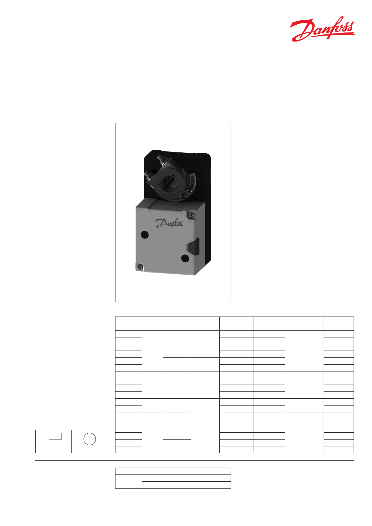
Actuators for dampers
AMD 210, 210 AS, AMD 220, 220 AS
AMD 310, 310 AS, AMD 420, 420 AS
AMD 510, 510 AS, AMD 520, 520 AS
Description AMD actuators are used for the regulation of
air dampers of 90° angle of rotation to be used
in heating, ventilation and air conditioning
applications (HVAC).
Features:
• Manual operation
• Rotation direction selection by switch
• 2/3 point control adjustable angle of rotation
by mechanical end stop min 20°.
• Modulating control ajdustable angle of
rotation with end stop.
• Position indication
• Overload protection
• Direct mounting with universal spindle clamp
• Anti-rotation strap for preventing actuator
from rotating
• Maintenance free
Ordering
Note:
* Actuator with built-in auxiliary switches
** D amper size:
a
b
S=a×b
S=π×r
r
2
Main Data:
• Nominal voltage (AC or DC):
230 V, 50/60 Hz
24 V, 50/60 Hz
• Control Input signal: modulating or 2/3 point
(depend on wiring)
• Torque: 5/8/10/15 Nm
• Rotation angle: 0- max. 95°
• Speed: 60-150 sec /90°
Typ e
AMD 210
AMD 210 AS 24 VAC /DC 1 aux. Switch * 08 2H11 01
AMD 210 230 VAC/ DC - 08 2H11 02
AMD 210 AS 230 VAC/ DC 1 aux. Switch * 08 2H11 03
AMD 220
AMD 220 AS 24 VAC/DC 1 aux. Switch * 08 2H11 05
AMD 310
AMD 310 AS 24 VAC /DC 1 aux. Switch * 0 82 H1107
AMD 310 23 0 VAC/D C - 082H1108
AMD 310 AS 230 VAC/ DC 1 aux. Switch * 0 82 H1109
AMD 420
AMD 420 AS 24 VAC /DC 1 aux. Switch * 0 82H1111
AMD 510
AMD 510 AS 24 VAC/DC 1 aux. Switch * 0 82H 1113
AMD 510 230 VAC/ DC - 0 82H 1114
AMD 510 AS 23 0 VAC/D C 1 aux. Switch * 0 82 H1115
AMD 520
AMD 520 AS 24 VAC/DC 1 aux. Switch * 0 82H 1117
Torque
(Nm) (s/90°) (V)
10 modulating
15
Control
signal
2/3-point 60 -120
5
modulating 100
8 2/3-point 60 -120
2/3-point
modulating
Speed Supply voltage
24 VAC /DC -
24 VAC /DC - 08 2H110 4
24 VAC /DC -
24 VAC /DC -
24 VAC /DC -
150
24 VAC /DC - 08 2H111 6
Auxiliary
switch
Max. da mper size
(m2)
1 **
1,6 * *
2 **
3 **
Code No.
08 2H11 00
08 2H11 06
08 2H111 0
08 2H111 2
Working cycles
DEN-SMT/SI
2/3-point >60.000 cycles (0°-95°-0°)
modulating
VD.IR.C3.02 © Danfoss 06/2015
>60.000 cycles (0°-95°-0°)
>1.000.000 partial cycles (±5°)
1
Page 2
R
L
R
L
Ad
Data sheet Actuators for dampers AMD 210(AS),220(AS), 310(AS), 420(AS), 510(AS), 520(AS)
Technical data
Note:
* depend on wiring
** at distance 1m
Operating mode
Typ e
Power supply V 24 AC/DC or 230 AC/DC ± 20%
Power consumption in motion
Power consumption in Stand by
(end p osition)
Frequency Hz 50/60
Control Input
Operating torque Nm 5 8 15 5 10 15
Rotation angle 0...max 95°
Ambient temperature
Ambient humidity 5...95% r.F., non- condensating (EN 60730 -1)
Storage and transport temperature
Protection Class III (24V) / II (230V)
Rated impulse voltage kV 4 (EN 60730-1) 0,8 (EN 60730-1)
Grade of enclosure / Degree of protection
Sound power level motor **
Weight kg 0,53
marking in accordance with standards
210/210A S
(24V/ 230V)
W
V
mA 0-20 (4-20) Ri = 500Ω
°C
dB(A)
Low voltage directive (LVD) 2006/95/EC: EN 60730-1, EN 60730-2-14
EMC Directive 2004/108/EC: EN 61000-6 -2, EN 61000-6-3 RoHS CE (2011/65/EU)
Valid for: AMD 210, 210AS, 310, 310AS, 510, 510AS
2- point.
Through connecting the power supply to BU+BN
(1+2) and the direction of rotation switch on
position “R” moves the actuator to position 1. Is
also BK (1+2+3) connected to the power supply
the actuator is moving to position 0.
310/310 AS
(24V/ 230V)
2/3 point * modulating 2/3 point *
/
510/510A S
(24V)
220/220AS
2 2,5
420/420AS
(24V)
−30 … 50
−30 … 80
(24V)
1
0-10 (2-10) Ri = 100 kΩ
IP 54
< 35
520/520AS
(24V)
Valid for: AMD 220, 220AS, 420, 420AS, 520, 520AS
Through connecting the power supply to
BU+BN (1+2) and a reference signal Y to BK (3) of
0(2)…10VDC, moves the actuator to its specied
position. The actual damper position 0…100%
is a feedback signal U for example to share the
signal with other actuators.
510/510A S
(230V)
/
4 (EN 60730-1)
3- point.
Through connecting the power supply to BU+BN
(1+2) and the direction of rotation switch on
position “R” moves the actuator to position 1.
If the power supply is interrupted the actuator
maintains its current position. Is also BU+BK (1+3)
connected to the power supply the actuator is
moving in direction 0.
The actuator is overload-proof, requires no limit
switches and automatically stops when the end
stop is reached.
Direct mounting Simple direct mounting on the damper spindle
with a universal spindle clamp, supplied with an
anti-rotation strap to prevent the actuator from
rotating.
Manual operation
Manual operation is possible with the selfresetting pushbutton (the gearing latch remains
disengaged as long as the pushbutton is pressed)
Rotary direction switch
The actuator is overload-proof, requires no limit
switches and automatically stops when the end
stop is reached.
p
R= clockwise
R= clockwise
L= counter clockwise
Valid for: AMD 210, 210AS 310, 310AS
Adp= adaption
L= counter clockwise
Valid for: AMD 510, 510AS
2
VD.IR.C3.02 © Danfoss 06/2015
DEN-SMT/SI
Page 3

Montage/ mounting/montage/montaggio/ montaje:
Funktionen/ function/ fonction/ funcione/ función:
Anschlussschema/ connection scheme/ schema de connexion/
schema di collegamento/ esquema de conexiones:
1
2
Data sheet Actuators for dampers AMD 210(AS),220(AS), 310(AS), 420(AS), 510(AS), 520(AS)
Montage/ mounting/montage/montaggio/ montaje:
Funktionen/ function/ fonction/ funcione/ función:
Montage/ mounting/montage/montaggio/ montaje:
Funktionen/ function/ fonction/ funcione/ función:
Montage/ mounting/montage/montaggio/ montaje:
Funktionen/ function/ fonction/ funcione/ función:
Montage/ mounting/montage/montaggio/ montaje:
Funktionen/ function/ fonction/ funcione/ función:
Anschlussschema/ connection scheme/ schema de connexion/
schema di collegamento/ esquema de conexiones:
1
Mode- switch
Valid for AMD:
(220, 220AS, 420, 420AS, 520, 520AS)
Adaption drive (Adp)
Valid for AMD:
(510, 510AS, 220, 420, 520)
Auxiliary switches
Valid for AMD:
(210AS, 310AS, 510AS, 220AS, 420AS, 520AS)
Mode switch with four rast positions at the
housing
- Rotary direction Normal 2-10 V
- Rotary direction Normal 0-10 V
-
Adp= adaption
- Rotary direction invers 2-10 V
- Rotary direction invers 0-10 V
-Adaption on angle of rotation < 90°
-Actuator power-o
-Setting the mechanical end stops
-Actuator power-on
-Adaption to enable
-Actuator adaption on angular range
-Adaption to disable
-“Y” refers to the measured angular range
Installation
Dimensions
DEN-SMT/SI
The actuators should be mounted in a dry
anvironment, absolutely free from acrid fumes.
In case of outdoor installation, the actuator has
to be protected against climatic inuences by
suitable measures.
VD.IR.C3.02 © Danfoss 06/2015
Clamp coupling dimensions: Ø 8-20 mm
3
Page 4

Funktionen/ function/ fonction/ funcione/ función:
Anschlussschema/ connection scheme/ schema de connexion/
schema di collegamento/ esquema de conexiones:
Data sheet Actuators for dampers AMD 210(AS),220(AS), 310(AS), 420(AS), 510(AS), 520(AS)
Wiring
AMD 210, 310, 510
(24VAC /DC)
AMD 210, 310, 510
(230VAC)
AMD 220, 420, 520
(24VAC /DC)
AMD 210AS,310AS,510A S
(24VAC /DC)
AMD 210AS,310AS,510A S
(230VAC)
AMD 220AS, 420AS, 520AS
(24VAC /DC)
4
VD.IR.C3.02
Produce d by Danfoss A/S © 06/2 015
 Loading...