

Fact Sheet
Akva Lux II Se fully insulated substation
for direct heating w/mixing loop and instantaneous domestic hot water for single-family, semi-detached and terraced houses
FEATURES AND BENEFITS
• Possibility to connect LeanHeat Monitor for
remote parameters setting and monitoring
• Fully insulated with very low heat losses
• Direct heating, DHW heating based on flow
principle
• Innovative, energy-saving controller PTC2+
P in combination with high performance
heat exchanger for on-demand water
heating without no-load losses function
• Ensuring the lowest return temperature by
special Danfoss technologies specifically
developed for substations
• Customer-specific solutions, specially
adapted to the applicable technical
regulations
• Advanced electronic control of heating (HE)
with weather compensation.
• Pipes and heat exchanger made of stainless
steel, connections with EPDM gaskets.
• Pipes connection in top or bottom of
substation = Savings in installations costs
• Capacity: 35-55 kW DHW, HE 20 kW
Application
Akva Lux II Se is a fully insulated district
heating substation for direct heating with
mixing loop and instantaneous domestic hot
water, featuring high performance and simple
operation. The Akva Lux II Se covers both the
DHW and heating requirements of large and
small single-family houses and is also suitable
for large projects.
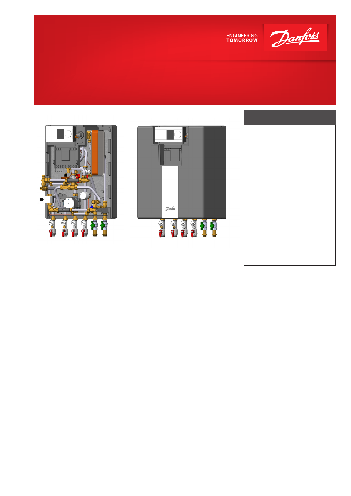
Construction
The Akva Lux II Se substation is available in two
main types with a plate heat exchanger for
domestic hot water production type XB 06H-1
26, XB 06H-1 40 or XB 06H+ 60.
The substation also features safety and nonreturn valve on the cold water connection,
ball valves and sensor pockets as well as a
differential pressure controller, energy-efficient
circulation pump, strainers, bypass valve, an
energy-saving domestic hot water controller
Danfoss PTC2+P, and a removable fitting piece
for installation of heat meter in the district
heating supply and return line.
The heating temperature is controlled by an
electronic ECL 310 controller with weather
compensation, which enables further energy
savings.
The heating side features a mixing loop, which
provides a suitable temperature level e.g. for
floor heating.
The substation is suitable and ready for
connecting re-circulation and leak detection
equipment.
Design
The design emphasizes a user-friendly placement of all components.
The Akva Lux II Se is supplied with an elegant
insulation cover and the removable cover
plate in the front insulation allows easy
access to components for regulation and
maintenance purposes.
The unit is delivered as standard with pipe
connection downwards, but a mounting
plate and pipe set are available as optional
equipment, enabling pipe connection to be
made in top.
Heat exchanger for DHW heating
The substation is based on a brazed, highly
efficient plate heat exchanger, which is
controlled by a thermostatic and pressure
controlled PTC2+P DHW controller.
The Danfoss PTC2+P DHW controller with
integrated differential pressure controller and
energy saving function ensures that the heat
exchanger is cold during standby.
Bypass (thermostatic circulation)
The substation supplied with a thermostatically controlled bypass, which ensures that
hot water is produced immediately, when
tapping starts. The bypass temperature is set
with due consideration of the best DHW comfort and energy savings balance. DHW re-circulation can be easily added to the substation
when it is required.
Domestic hot water recirculation
The substation is prepared for connection
to systems with DHW recirculation. Switching to DHW recirculation is possible from a
constructional point of view, requiring only
mounting of a separate circulation set (see
options).
The circulation temperature is set independently of the set DHW temperature. This
ensures the best possible DHW comfort,
very low standby losses and return temperature and thus a very good district heating
economy.
Mounting of heat meter
The substation is equipped with 3/4” fitting
pieces in the DH return or supply flow for fitting of a heat meter, - alternatively in both DH
return and supply flow for leak detection.
Service and maintenance
The substation is very service-friendly and
easy to install. It is mounted on the wall and
as all pipes are placed in pipe bracket distance, it is possible to establish a nice piping. The removable cover plate in the front
allows easy access to the specially designed
chamber where most frequently used components such as ECL310 and PTC2+P are located. The easy access chamber enables faster commissioning and maintenance without
removing the whole cover of the substation.
Calculator of the heat meter can also be
mounted into this chamber for easy reading.
districtenergy.danfoss.com
55
2
3
4
5
6
7
8
9
10
11
12
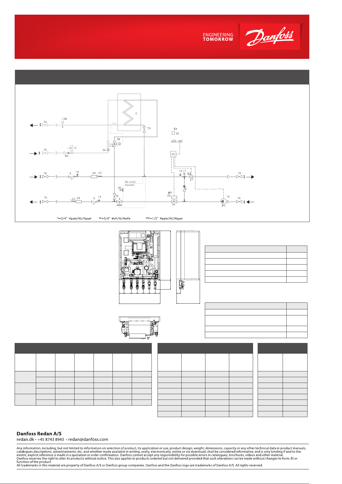
CIRCUIT DIAGRAM EXAMPLE
DHW
DCW
DH
Supply
DH
Return
Design specifications:
Nominal pressure (primary): PN16
Nominal pressure (DHW): PN10
Max. supply temperature: 110 °C (design temp.)
Min. ΔP: See capacity examples
Brazing material (HEX): Copper
Weight: Max. 24 kg
Insulation: Polypropylene
EPP λ 0.039
Electrical supply: 230 V AC
Dimensions (mm):
with insulation: H 785 × B 550 × T 315
Connections sizes:
DH, DCW, DHW, HE: G ¾“ IT (ext. thread)
Circulation: R ½“ ET (ext. thread)
Recirculation:
Remember to order circulation set for systems
that feature DHW recirculation.
Dimensional sketch:
65 100 80 80 80 80 65
1 2 3 4 5 6
550
1 Plate heat exchanger DHW
4. Diff. pressure controller
5 Strainer
5A Filter for PTC2
6 Non-return valve
6A Non-return valve insert
7 Ball valve
10 Circulation pump
12 Safety valve DHW, 10 bar
13 Thermometer
14 Manometer connection
23 Sensor pocket ½”for heat meter
24 Flex. fitting piece for heat meter
3/4” x 110-165 mm
25 Danfoss Controller ECL 310/A230
Connections:
1. District heating (DH) supply 2. District heating (DH) return
3. Heating (HE) return 4. Heating (HE) supply
5. Domestic hot water (DHW) 6. Domestic cold water
Basic type Code No
660
Type 1 PWH, EPP insulated cover 145B5190
Type 2 PWH, EPP insulated cover 145B5191
Type 3* PWH, EPP insulated cover 145B5192
Type 1 StS* PWH, EPP insulated cover 145B5193
Type 2 StS* PWH, EPP insulated cover 145B5194
125
55
315
* Suitable for low temperature district heating at supply temperatures in the range 50-70°C.
** StS = Stainless steel
Option prices (loose delivery) Option
Circulation set incl. pipe for mounting on site 145H4438
Mounting plate for connection of pipes in
top of substatio n
Pipe set (2 pipes) for mounting plate 145H4856
Cover plate in the front insulation 183L5003
26 Outdoor sensor, ESMT
27 Danfoss sensor, ESMC
29 Danfoss actuator HE, AMV 150
30 Thermostatic valve VS2
38 PTC2+P controller
40 Thermostat for Bypass/Re-circ.
-------------------------------------Options (not part of delivery):
61 Circulation pipe
2
62 Non-return valve
64 Circulation pump
1
For meters with 1 “thread, order a separate
1
fitting set, see table below
2
Circulation pipe set for DHW re-circulation
must be purchased as an option, see below
HE
Supply
HE
Return
145H4855
DHW: CAPACITY EXAMPLES 10 °C/50 °C
Plate heat
exchanger
HEX
XB 06H-1 26
Typ 1
XB 06H-1 40
Typ 2
XB06H+ 60
Typ 3
DHW
capacity
[kW]
Supply flow
primary
[°C]
Supply flow
secondary
[°C]
35,0 65 22 25 714 12, 5
35,0 90 16 8 414 12, 5
55,0 65 25 49 1116 19,7
55,0 90 16 16 636 19,7
32,3 55 20 24 800 13,3
41,0 55 21 40 1030 17,2
* Stated pressure loss values are incl. of pipes, HEX and valves
© Danfoss | DEN-DKDHR | 2021 .09
Pressure
loss
Primary
[*bar]
Flow rate
primary
[l/min]
DHW
tap load
[l/min]
HEATING: CAPACITY EXAMPLES
HE
capacity
[kW]
HE circuit,t
primary
[°C]
HE circuit,t
secondary
[°C]
9 25 5 310
9 40 5 194
9 50 5 155
10 25 15 344
15 30 20 430
15 30 30 430
20 40 40 430
15 30 30 430
Flow rate
primary
[l/min]
TOTAL
Pressure loss
primary
[total ***bar]
1
0.42
2
0.28
3
0.16
2
0.30
2
0.33
2
0.33
3
0.29
4
0.44
Flow rate
primary
(total3) [l/ h]
1
1070
2
870
3
660
2
930
2
990
2
990
3
820
4
1210
*** Calculated at 70% of the heating capacity + DHW capacity of 32.3 kW at a district heating supply temperature
of 551, 602 or 703 °
4
) Combination with 70% of the heating capacity + DHW capacity 41 kW (60+ HEX)
C.
AM391471895971en-010101
 Loading...