

Page 1
Data Sheet
Electric expansion valves
Type AKVA 10, AKVA 15 and AKVA 20
Designed for ammonia refrigerating plant
AKVA are electric expansion valves designed for
ammonia refrigerating plant.
The AKVA valves are normally controlled by a
controller from Danfoss’ range of ADAP-KOOL
controllers.
The AKVA valves are supplied as a component
programme, as follows:
• Separate valve
• Separate coil with terminal box or cable
• Spare parts in the form upper part, orice and
lter
The individual capacities are indicated with a
number forming part of the type designation.
The number represents the size of the orice of
the valve in question.
A valve with orice 3 will for example be
designated AKVA 10-3.
The orice assembly is replaceable.
Features
• The valve requires no adjustment
• Wide regulation range
• Replaceable orice assembly
• Wide range of coils for d.c. and a.c.
• Quick reaction in whole range of stated
capacity.
• In some applications AKVA can be used both
as expansion valve and solenoid valve.
• Classication: DNV, CRN, BV, EAC etc. To get
an updated list of certication on the
products please contact your local Danfoss
Sales Company.
®
AI183786440857en-000801
Page 2
0
6
12
18
Electric expansion valves, Type AKVA 10, AKVA 15 & AKVA 20
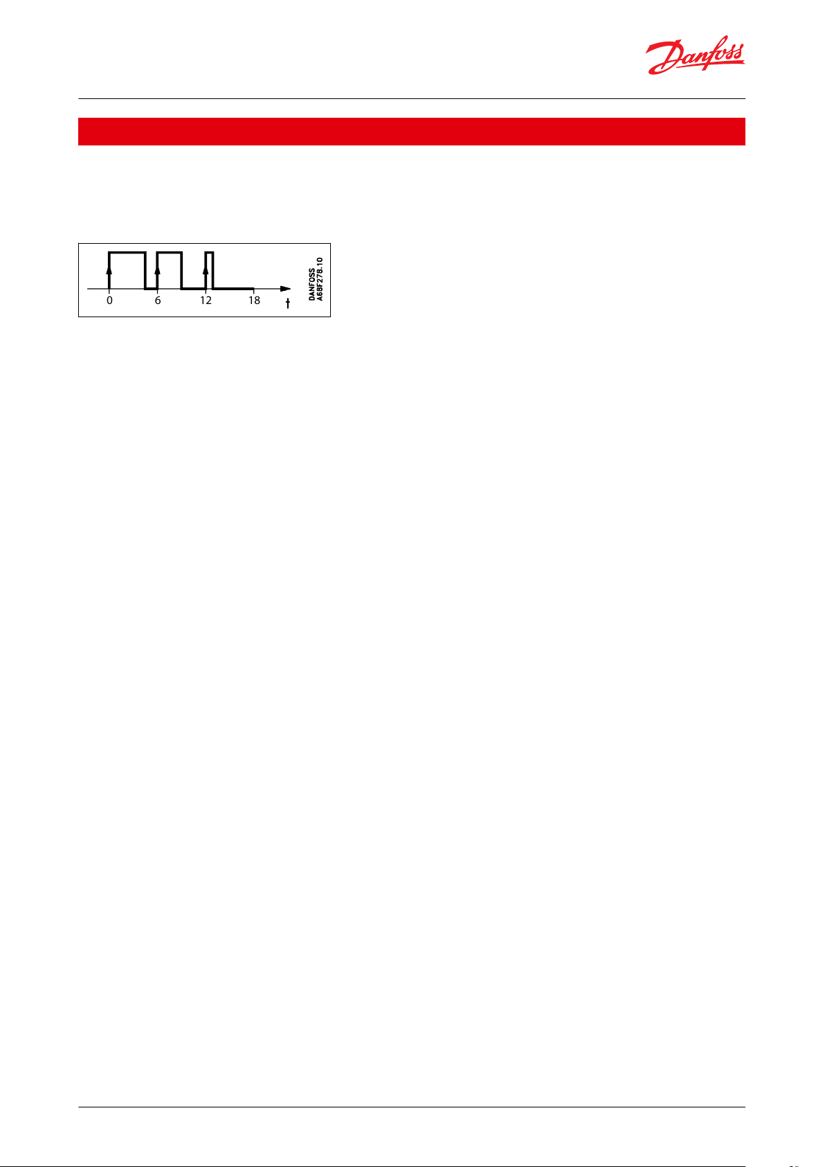
Functions
The valve capacity is regulated by means of pulse-width modulation. Within a period of six seconds a voltage signal
from the controller will be transmitted to and removed from the valve coil. This makes the valve open and close for
the ow of refrigerant.
Figure 1: Function
The relation between this opening and closing time indicates the actual capacity. If there is an intense need for
refrigeration, the valve will remain open for almost all six seconds of the period. If the required amount of
refrigeration is modest, the valve will only stay open during a fraction of the period. The amount of refrigeration
needed is determined by the controller. When no refrigeration is required, the valve will remain closed.In some
applications, AKVA can advantage-ously be used both as expansion valve and solenoid valve. See Applications
© Danfoss | Climate Solutions | 2021.05 AI183786440857en-000801 | 2
Page 3

Electric expansion valves, Type AKVA 10, AKVA 15 & AKVA 20
Applications
Recommendations
It is important to realize when AKVA is operating, that the valve always is fully open or fully closed. That means that
this way of operation should always be considered during the refrigeration design. (Piping, liquid velocity, sub
cooling etc.)
Danfoss have the following recommendations/guidelines to be taken into considerations:
• In 1:1 applications (1 evaporator, 1 condenser and 1 compressor) chillers with a small amount of refrigerant or
installed in front of a Plate Heat Exchangers, it must be observed that every time the AKVA is fully open or closed it
will have a signicant impact on the hole system. (e.g. pressure variations on suction side).
Please observe that the performance of such a system is not only related to one component. (e.g. AKVA) Other
factors which is very important to include in the overall refrigeration system design:
◦ Liquid distribution at and design of evaporator
◦ total evaporator coil is of adequate length thus superheat can be controlled within the entered period time
(normal 6 sec. or 3 sec.)
◦ mounting principle of temperature sensor, to ensure a steady and fast signal can be detected by the electronic
system.
• If pressure dependent valves like, ICS with pilots like CVP e.t.c., is installed between evaporator and compressor, it
can eect the lifetime of ICS, because the piston of the ICS will operate together with operation of AKVA. Type of
refrigerant and evaporator has a big inuende of the size of pulsations after the evaporator and in front of the ICS.
• AKVA is a direct pressure independent valve. That means that if non-Danfoss electronic controllers is used,
intelligent and fast optimal control is needed, because the quick pressure changes only can be detected and
compensated via the electronic control system.
• Liquid lines must be designed according to AKVA capacity and not evaporator capacity.
• To avoid ash-gas ensure sucient sub-cooling or design liquid lines thus to big pressure drop is avoided, when
AKVA is open. If not sucient subcooling is not obtained (normally 4K) it will have an impact on the lifetime of the
vale).
• Where the demand for safety level is extremely high, (e.g. Liquid Level Control in a pump seperator) an extra valve
can be installed in front of AKVA to avoid leakage. This valve must be Danfoss type EVRAT.
• Always install a 100 µm lter in front of AKVA 15 and AKVA 20 valves.
• If AKVA has to be used in chillers. Please contact Danfoss.
© Danfoss | Climate Solutions | 2021.05 AI183786440857en-000801 | 3
Page 4

Electric expansion valves, Type AKVA 10, AKVA 15 & AKVA 20
Media
Refrigerants
For R717 (Ammonia) and R744 (CO2)
.
New refrigerants
Danfoss products are continually evaluated for use with new refrigerants depending on market requirements.
When a refrigerant is approved for use by Danfoss, it is added to the relevant portfolio, and the R number of the
refrigerant (e.g. R513A) will be added to the technical data of the code number. Therefore, products for specic
refrigerants are best checked at store.danfoss.com/en/, or by contacting your local Danfoss representative.
© Danfoss | Climate Solutions | 2021.05 AI183786440857en-000801 | 4
Page 5
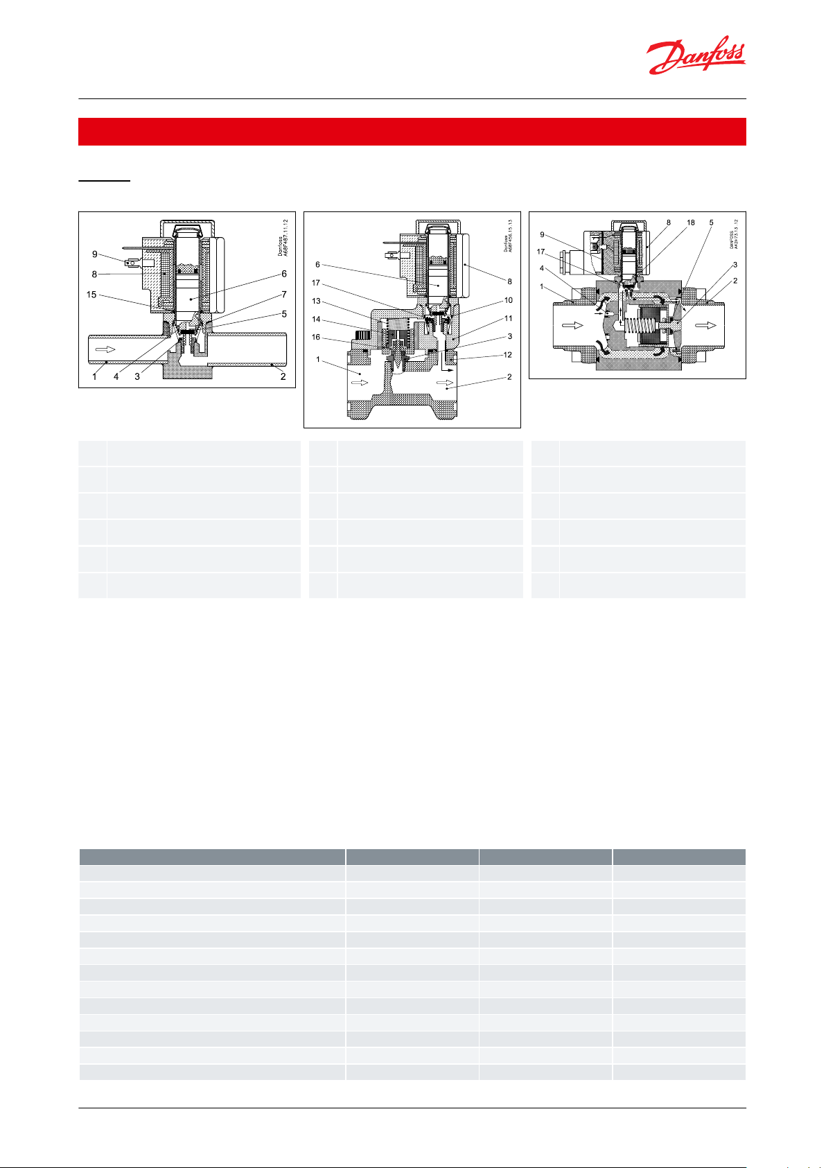
1.2.3.4.5.6.7.8.9.
10.
11.
12.
13.
14.
15.
16.
17.
18.
Inlet
Outlet
Orice
Filter
Valve seat
Armature
Aluminium gasket
Coil
DIN plug
Filter
Cover
Valve body
Spring
Orice assembly
O-ring
Piston assembly
Pilot orice
Pilot valve
Valve type
AKVA 10
AKVA 15
AKVA 20
Tolerance of coil voltage
+10 / -15%
+10 / -15%
+10 / -15%
Enclosure to IEC 529
Max. IP 67
Max. IP 67
Max. IP 67
Working principle (Pulse-width modulation)
PWM
PWM
PWM
Recommend period of time
6 seconds
6 seconds
6 seconds
Capacity (R717)
4 to 100 kW
125 to 500 kW
500 to 3150 kW
Regulation range
10 - 100%
10 - 100%
10 - 100%
Connection
Weld
Weld
Weld
Media temperature
- 50 to 60 °C
- 40 to 60 °C
- 40 to 60 °C
Ambient temperature
- 50 to 50 °C
- 40 to 50 °C
- 40 to 50 °C
Leak of valve seat
< 0.02% of kv-value
< 0.02% of kv-value
< 0.02% of kv-value
MOPD
18 bar
22 bar
18 bar
Filter
Internal 100 µm replaceable
external 100 µm
external 100 µm
Max. working pressure
PS = 42 bar
PS = 42 bar
PS = 42 bar
Electric expansion valves, Type AKVA 10, AKVA 15 & AKVA 20
Product specication
Design
Figure 2: AKVA 10 Figure 3: AKVA 15 Figure 4: AKVA 20
The AKVA 10 valves covers a capacity range from 4 kW to 100 kW (R 717) and are divided into 8 capacity ranges. The
AKVA 10 valve bodies are made in stainless steel and have weld connections..
The AKVA 15 valves covers a capacity range from 125 kW to 500 kW (R 717) and are divided into 4 capacity ranges.
The AKVA 15 valves have ange connections.
The AKVA 20 valves cover a capacity range from 500 kW to 3150 kW (R 717) and are divided into 5 capacity ranges.
The AKVA 20 valve has weld connections.
The AKVA valves can be used for:
• Flooded evaporation (high/low pressure)
• Pump separators
• Direct expansion. See Applications.
If AKVA has to be used in chillers please contact Danfoss.
Table 1: Technical data
© Danfoss | Climate Solutions | 2021.05 AI183786440857en-000801 | 5
Page 6

Valve type
Capacity in kW at pressure drop across valve ∆p bar
2468101214
16
AKVA 10 - 1
2.2
3.1
3.7
4.1
4.4
4.755.2
AKVA 10 - 2
3.5
4.9
5.8
6.577.5
7.9
8.3
AKVA 10 - 3
5.6
7.7
9.1
10.2
11.1
11.9
12.5
13.1
AKVA 10 - 4
9.1
12.4
14.7
16.5
17.9
19.2
20.2
21.1
AKVA 10 - 5
14.2
19.4
22.9
25.72829.9
31.6
33
AKVA 10 - 6
23
31.2
36.4
41.44548.1
50.7
53.1
AKVA 10 - 7
36.6
49.3
58.16570.6
75.3
79.4
83
AKVA 10 - 8
59.1
78.9
93.5
104
112
120
126
131
AKVA 15 - 1
95.7
113
127
138
148
156
163
AKVA 15 - 2
153
181
203
221
236
250
261
AKVA 15 - 3
231
274
308
335
358
377
395
AKVA 15 - 4
383
455
510
555
593
625
655
AKVA 20 - 1
383
455
510
555
593
625
655
AKVA 20 - 2
612
726
814
886
947
999
1045
AKVA 20 - 3
959
1137
1275
1388
1482
1564
1635
AKVA 20 - 4
1552
1836
2057
2239
2391
2523
2639
AKVA 20 - 5
2479
2921
3267
3550
3789
3994
4174
Correction factor
2K4K10K
15K
20K
25K
30K
35K
40K
45K
50K
R717
1.01
1.00
0.98
0.96
0.94
0.92
0.91
0.89
0.87
0.86
0.85
Electric expansion valves, Type AKVA 10, AKVA 15 & AKVA 20
Capacity
Range: - 40 °C to 10 °C
Table 2: R717
Correction for subcooling
The liquid injected capacity must be corrected, if the subcooling deviates from 4 K. Use the actual correction factor
indicated in the table. Multiply the liquid injected capacity by the correction factor to obtain the corrected capacity.
Table 3: Correction factors for subcooling ∆t
sub
Dimensioning
To obtain an expansion valve that will function correctly under dierent load conditions it is necessary to consider
the following points when the valve has to be dimensioned.
These points must be dealt with in the following sequence:
1.
Evaporator capacity
2.
Pressure drop across the valve
3.
Correction for subcooling
4.
Correction for evaporating temperature
5.
Determination of valve size
6.
Correctly dimensioned liquid line
Example for a direct expansion system
Evaporator capacity
The evaporator capacity is found in the specications from the evaporator supplier.
Pressure drop across the valve
The pressure drop across the valve directly determines the capacity and must therefore be considered. The pressure
drop across the valve is normally calculated as the condensing pressure minus the evaporating pressure and other
pressure drops in the liquid line, distributor, evaporator, etc. It is indicated in the following formula: ∆pvalve = pc –
(pe + ∆p1 + ∆p3 + ∆p4)
© Danfoss | Climate Solutions | 2021.05 AI183786440857en-000801 | 6
Page 7
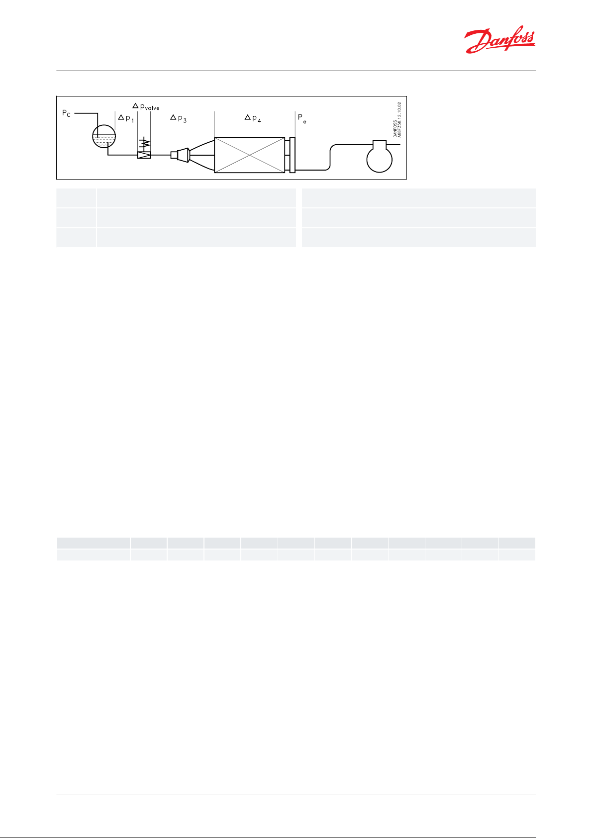
∆p
valvepcpe∆p1∆p3∆p4
pressure drop across the valve
condensing pressure
evaporating pressure
pressure drop across the liquid line
pressure drop across the distributor system
pressure drop across the evaporator
Correction factor
2K4K10K
15K
20K
25K
30K
35K
40K
45K
50K
R717
1.01
1.00
0.98
0.96
0.94
0.92
0.91
0.89
0.87
0.86
0.85
Electric expansion valves, Type AKVA 10, AKVA 15 & AKVA 20
Figure 5: Example of a direct expansion system
NOTE:
The pressure drop across the liquid line and the distributor system must be calculated on the basis of the valve’s
max. capacity, as the valve operates with pulse-width modulation.
Example of calculation of pressure drop across a valve:
• Refrigerant: R 717
• Condensing temperature: 35 °C (pc = 13.5 bar)
• Evaporating temperature: -20 °C (pe = 1.9 bar)
• ∆p1 = 0.2 bar
• ∆p3 = 0.8 bar
• ∆p4 = 0.1 bar
This will give you the following equation:
∆p
= pc – (pe + ∆p1 + ∆p3 + ∆p4)
valve
= 13.5 – (1.9 + 0.2 + 0.8 + 0.1)
= 10.5 bar
The found value for “pressure drop across the valve” is used later in the section “Determination of valve size”.
Correction for subcooling
The evaporator capacity used must be corrected, if the subcooling deviates from 4 K. Use the actual correction
factor indicated in the table. Multiply the evaporator capacity by the correction factor to obtain the corrected
capacity.
Table 4: Correction factors for subcooling ∆t
sub
Corrected capacity = evaporator capacity x correction factor.
The corrected capacity is used in the section “Determination of valve size”.
NOTE:
Too little subcooling may cause ash gas.
Example of correction:
Refrigerant: R 717
Evaporator capacity Qe: 300 kW
Subcooling: 10 K
Correction factor according to the table = 0.98
Corrected evaporator capacity = 300 x 0.98 = 294 kW
Correction for evaporating temperature (te)
To obtain a correctly dimensioned valve it is important that the application is considered. Depending on the
application, the valve should have an overcapacity enabling it to cope with the extra amount of refrigeration
needed during certain periods, e.g. during the defrost recovery process. The valve’s opening degree should
© Danfoss | Climate Solutions | 2021.05 AI183786440857en-000801 | 7
Page 8

Evaporating temperature te °C
50-10
-15
-20
-30
-40
AKVA 10, AKVA 15, AKVA 20
1.0
1.0
1.0
1.0
1.2
1.3
1.4
Electric expansion valves, Type AKVA 10, AKVA 15 & AKVA 20
therefore be between 50 and 75% when regulating. In this way it is ensured that the valve has a suciently wide
regulation range, so that it can manage changed loads at or near the normal working point. Correction factors
based on the evaporating temperature are indicated below:
Table 5: Correction factors for evaporating temperature (te)
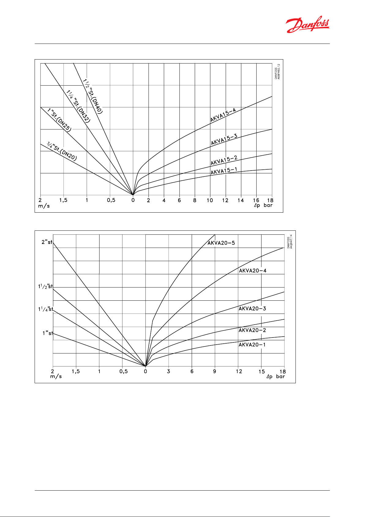
Correctly dimensioned liquid line
To obtain a correct supply of liquid to the AKVA valve, the liquid line to the individual AKVA valve must be correctly
dimensioned. The liquid ow rate must not exceed 1 m/sec at a fully open valve.
This must be observed on account of the pressure drop in the liquid line (lack of subcooling) and pulsations in the
liquid line. Dimensioning of the liquid line must be based on the capacity of the valve at the pressure drop with
which it is operating (cf. capacity table), and not on the evaporator's capacity, see gures below
Figure 6: AKVA-10
© Danfoss | Climate Solutions | 2021.05 AI183786440857en-000801 | 8
Page 9
Electric expansion valves, Type AKVA 10, AKVA 15 & AKVA 20
Figure 7: AKVA-15
Figure 8: AKVA-20
© Danfoss | Climate Solutions | 2021.05 AI183786440857en-000801 | 9
Page 10

Inlet
Outlet
Valve type
ABC
Connection
Weight without
coil
Inlet
Outletmmmmmmin.
in.
kg
AKVA 10
1 – 66060
113
3⁄81
⁄2
0.35
AKVA 10
7 – 86060
113
1⁄23
⁄4
0.35
AKVA 15
AKVA 20
L = 148 mm
Weight without coil = 2.0 kg
Weight without coil = 4.1 kg
Electric expansion valves, Type AKVA 10, AKVA 15 & AKVA 20
Dimension and weight
Figure 9: Dimension
Table 6: AKVA 10
Table 7: Dimensions
Determination of valve size
When the valve size meeting the required capacity is selected it is important to note that the capacity indications
are the valve’s rated capacity, i.e. when the valve is 100% open. In this section we tell you how the valve’s size is
determined.
There are three factors that have an inuence on the choice of the valve:
• the pressure drop across the valve
• the corrected capacity (correction for subcooling)
• the corrected capacity for evaporating temperature
The three factors have been described earlier in this section on dimensioning.
When these three factors have been established, the selection of the valve can be made:
• First you multiply the “corrected capacity” by a value stated in the table.
• Use the new value in the capacity table in combination with the pressure drop value.
• Now select the valve size.
© Danfoss | Climate Solutions | 2021.05 AI183786440857en-000801 | 10
Page 11

Electric expansion valves, Type AKVA 10, AKVA 15 & AKVA 20
Example of selection of valve
Use as starting point the two earlier mentioned examples, where the following two values have been obtained:
∆pvalve = 10.5 bar
Q
e corrected
= 294 kW
From "Table 5: Correction factors for evaporating temperature (te)", factor 1.2 is given for the evaporating
temperature -20 °C.
The dimensioned capacity will then be: 1.2 x 294 kW = 353 kW.
Now select a valve size from table 8 "Rated Capacity".
With the given values ∆p
= 10.5 bar and a capacity of 353 kW, AKVA 15 - 4 is selected.
valve
This valve will have a capacity of approx. 555 kW.
© Danfoss | Climate Solutions | 2021.05 AI183786440857en-000801 | 11
Page 12

Valve type
Rated capacity
(1)
kv-value
Connections Inlet
x outlet
Code no.
Connections Inlet
x outlet
Code no.
kW
tons
m3/h
in.
in.
AKVA 10-141.1
0.01
3
⁄8 × 1⁄2
068F3261
1
⁄2 × 3⁄4
068F3281
AKVA 10-2
6.3
1.8
0.015
3
⁄8 × 1⁄2
068F3262
1
⁄2 × 3⁄4
068F3282
AKVA 10-3102.8
0.022
3
⁄8 × 1⁄2
068F3263
1
⁄2 × 3⁄4
068F3283
AKVA 10-4164.5
0.038
3
⁄8 × 1⁄2
068F3264
1
⁄2 × 3⁄4
068F3284
AKVA 10-5257.1
0.055
3
⁄8 × 1⁄2
068F3265
1
⁄2 × 3⁄4
068F3285
AKVA 10-64011.4
0.103
3
⁄8 × 1⁄2
068F3266
1
⁄2 × 3⁄4
068F3286
AKVA 10-76317.9
0.162
1
⁄2 × 3⁄4
068F3267
AKVA 10-8
100
28.4
0.251
1
⁄2 × 3⁄4
068F3268
AKVA 15-1
125350.25
Flange
068F5020
(2)
AKVA 15-2
200600.4
Flange
068F5023
(2)
AKVA 15-3
300900.63
Flange
068F5026
(2)
AKVA 15-4
500
1401Flange
068F5029
(2)
AKVA 20-1
500
140
1
1
1
⁄4 × 1 1⁄4
042H2101
AKVA 20-2
800
240
1.6
1
1
⁄4 × 1 1⁄4
042H2102
AKVA 20-3
1250
350
2.5
1
1
⁄4 × 1 1⁄4
042H2103
AKVA 20-4
2000
600
4
1
1
⁄2 × 1 1⁄2
042H2104
AKVA 20-5
3150
900
6.3
2 × 2
042H2105
Valve type
Connection (in.)
Code no.
AKVA 15-1 to 4
3
⁄4
027N1220
1
027N1225
Electric expansion valves, Type AKVA 10, AKVA 15 & AKVA 20
Ordering
Rated capacity and ordering
Figure 10: Ordering
Table 8: Rated capacity
(1)
(1)
Rated capacities are based on
Rated capacities are based on
Condensing temperature tc = 32 °C
Condensing temperature tc = 32 °C
Liquid temperature tl = 28 °C
Liquid temperature tl = 28 °C
Evaporating temperature te = 5 °C
Evaporating temperature te = 5 °C
(2)
(2)
Incl. bolts and gaskets but without anges
Incl. bolts and gaskets but without anges
Figure 11: Flange
Table 9: Flange set for AKVA 15
© Danfoss | Climate Solutions | 2021.05 AI183786440857en-000801 | 12
Page 13

Strainer type
Code no.
House
Strainer insert 100 mm
FIA 20 D STR
148B5343
148H3122
FIA 25 D STR
148B5443
148H3123
FIA 32 D STR
148B5544
FIA 40 D STR
148B5625
FIA 50 D STR
148B5713
148H3157
AKVA 20
FIA
Electric expansion valves, Type AKVA 10, AKVA 15 & AKVA 20
Accessories
Strainer
On plants with ammonia and similar industrial plant a strainer must be mounted in front of AKVA 15 and AKVA 20.
AKVA 10 has built-in strainer and external strainer is not necessary.
Figure 12: Strainer
Table 10: Recommended strainer for AKVA 15 / 20
For further information: see Danfoss catalogue AI222586432958
Figure 13: Example of combinations
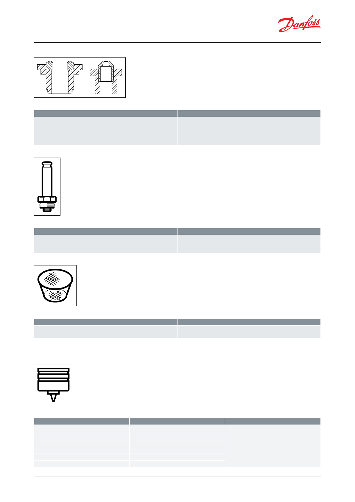
Spare parts
AKVA 10
Figure 14: Orice
© Danfoss | Climate Solutions | 2021.05 AI183786440857en-000801 | 13
Page 14

Type
Code no.
Contents
AKVA 10-1
068F0526
1 pcs. orice
1 pcs. Al. gasket
1 pcs. cap for coil
AKVA 10-2
068F0527
AKVA 10-3
068F0528
AKVA 10-4
068F0529
AKVA 10-5
068F0530
AKVA 10-6
068F0531
AKVA 10-7
068F0532
AKVA 10-8
068F0533
Code no.
Contents
068F0540
10 pcs. lters
10 pcs. Al. gaskets
Code no.
Contents
068F5045
1 pcs. armature
1 pcs. armature tube
1 pcs. Al. gasket
Type
Code no.
Contents
AKVA 15-1
068F5265
1 pcs. piston assembly
1 pcs. gasket
1 pcs. O-ring
2 pcs. labels
AKVA 15-2
068F5266
AKVA 15-3
068F5267
AKVA 15-4
068F5268
Type
Code no.
Contents
Gasket set
068F5264
Complete gasket set
Electric expansion valves, Type AKVA 10, AKVA 15 & AKVA 20
Table 11: Orice
Figure 15: Filter
Table 12: Filter
Figure 16: Upper part
Table 13: Upper part
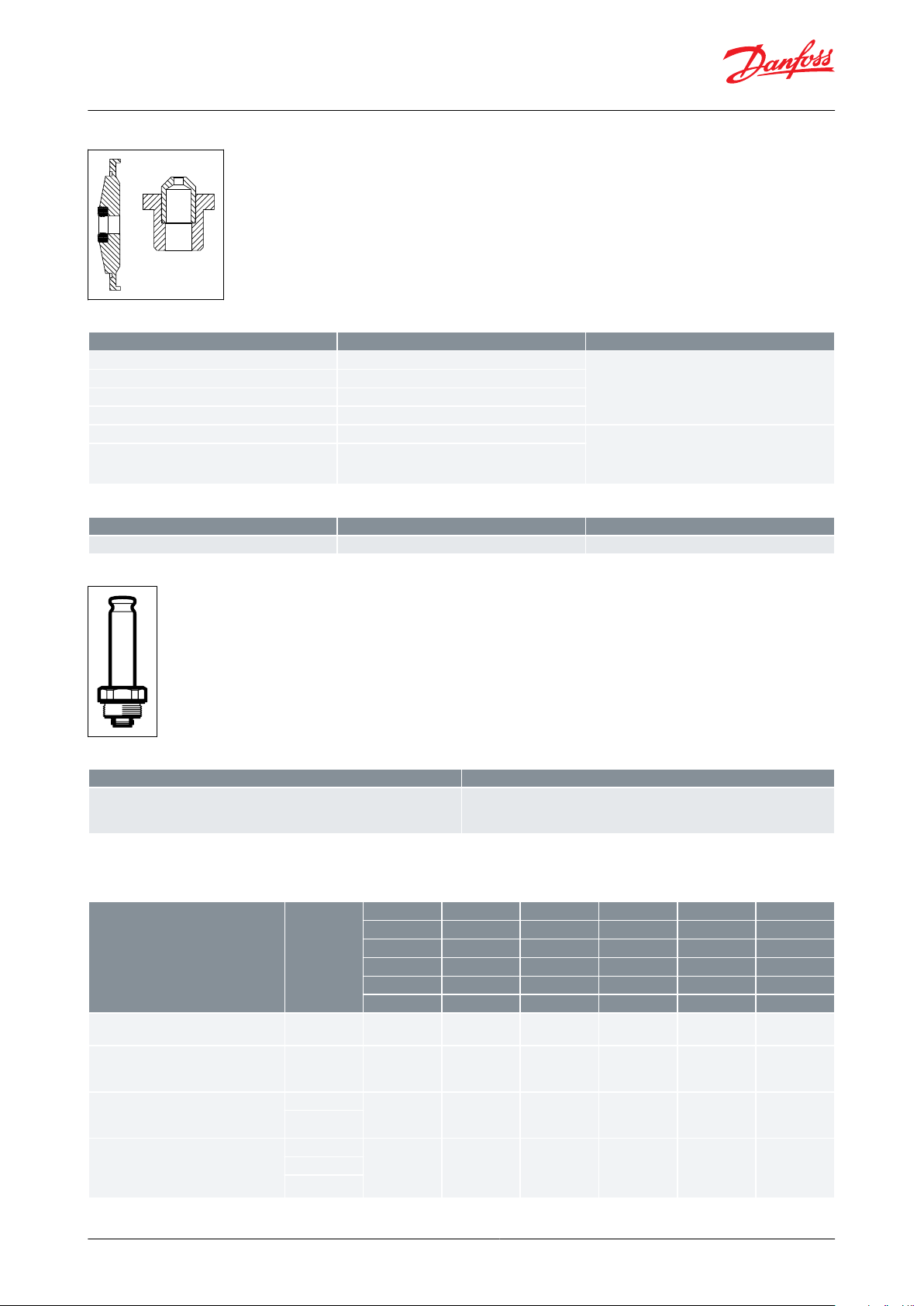
AKVA 15
Figure 17: Piston
Table 14: Piston
Table 15: Piston
© Danfoss | Climate Solutions | 2021.05 AI183786440857en-000801 | 14
Page 15
Code no.
Contents
068F5261
Main orice
Pilot orice
Al gaskets
O-rings
Gasket
Code no.
Contents
068F5045
1 pcs. armature
1 pcs. armature tube
1 pcs. Al. gasket
Code no.
Contents
068F0540
10 pcs. lters
10 pcs. Al. gaskets
Type
Code no.
Contents
AKVA 20-0.6
042H2039
1 pcs. piston assembly
3 pcs. O-rings
AKVA 20-1
042H2040
AKVA 20-2
042H2041
AKVA 20-3
042H2042
AKVA 20-4
042H2043
AKVA 20-5
042H2044
Electric expansion valves, Type AKVA 10, AKVA 15 & AKVA 20
Figure 18: Orice set
Table 16: Orice set
Figure 19: Upper part
Table 17: Upper part
Figure 20: Filter
Table 18: Filter
AKVA 20
Figure 21: Piston
Table 19: Piston
© Danfoss | Climate Solutions | 2021.05 AI183786440857en-000801 | 15
Page 16
Type
Code no.
Contents
AKVA 20-0.6
068F5270
Main orice, dia. 8 mm
Pilot orice, dia. 1.8 mm
2 pcs. Al. gaskets
O-ring
AKVA 20-1
068F5270
AKVA 20-2
068F5270
AKVA 20-3
068F5270
AKVA 20-4
068F5271
Main orice, dia. 14 mm
Pilot orice, dia. 2.4 mm
2 pcs. Al. gaskets
O-ring
AKVA 20-5
068F5271
Type
Code no.
Contents
Gasket set
042H0160
Complete gasket set for new and old valves
Code no.
Contents
068F5045
1 pcs. armature
1 pcs. armature tube
1 pcs. Al. gasket
D.C. coils
Code no.
AKVA
AKVA
AKVA
AKVA
AKVA
AKVA
10-1
10-6
10-7
15-1
20-1
20-4
10-2
10-8
15-2
20-2
20-5
10-3
15-3
20-3
10-4
15-4
10-5
220 V DC 20 W, standard
with terminal box
018F6851++++++
100 V DC 18 W, special
with terminal box
with DIN plugs
018F6780++++++
230 V DC 18 W, special
with terminal box
with DIN plugs
018F6781
(1)
+++++
+
018F6991
(1)
230 V DC 18 W, special
with 2.5 m cable
with 4.0 m cable
with 8.0 m cable
018F6288
(1)
+++++
+
018F6278
(1)
018F6279
(1)
Electric expansion valves, Type AKVA 10, AKVA 15 & AKVA 20
Figure 22: Orice set
Table 20: Orice set
Table 21: Gasket set
Figure 23: Upper part
Table 22: Upper part
Coils for AKVA valves
Table 23: Coils for AKVA valves
© Danfoss | Climate Solutions | 2021.05 AI183786440857en-000801 | 16
Page 17

A.C. coils
Code no.
AKVA
AKVA
AKVA
AKVA
AKVA
AKVA
10-1
10-6
10-7
15-1
20-1
20-4
10-2
10-8
15-2
20-2
20-5
10-3
15-3
20-3
10-4
15-4
10-5
240 V AC 10 W, 50 Hz with terminal
box with DIN plugs
018F6702
++–+–
–
018F6177
240 V AC 10 W, 60 Hz
with terminal box
with DIN plugs
018F6713++–+––
240 V a.c. 12 W, 50 Hz
with terminal box
018F6802+++++–
220 V AC 10 W, 50 Hz with
terminal box with DIN plugs
018F6701
++–+–
–
018F6176
220 V a.c. 10 W, 60 Hz
with terminal box with DIN plugs
018F6714
++–+–
–
018F6189
220 V AC 12 W, 50 Hz
with terminal box
018F6801++–++–
220 V a.c. 12 W, 60 Hz
with terminal box
018F6814++–++–
115 V AC 10 W, 50 Hz
with terminal box
with DIN plugs
018F6711
++–+–
–
018F6186
115 V AC 10 W, 60 Hz
with terminal box
with DIN plugs
018F6710
++–+–
–
018F6185
110 V a.c. 12 W, 50 Hz
with terminal box
018F6811++–++–
110 V a.c. 12 W, 60 Hz
with terminal box
018F6813++–++–
24 V AC 10 W, 50 Hz
with terminal box
with DIN plugs
018F6707
+––+–
–
018F6182
24 V AC 10 W, 60 Hz
with terminal box
with DIN plugs
018F6715+––+––
24 V AC 12 W, 50 Hz
with terminal box
018F6807+––+++
24 V AC 12 W, 60 Hz
with terminal box
018F6815+––+++
24 V AC 20 W, 50 Hz
with terminal box
018F6901++++++
24 V AC 20 W, 60 Hz
with terminal box
018F6902++++++
Electric expansion valves, Type AKVA 10, AKVA 15 & AKVA 20
(1)
(1)
Recommended for commercial refrigeration plant
Recommended for commercial refrigeration plant
Table 24: Coils for AKVA valves
© Danfoss | Climate Solutions | 2021.05 AI183786440857en-000801 | 17
Page 18
Type
File name
Document type
Document topic
Approval authority
AKVA
MH7648
Electrical - Safety Certicate
UL
MD 033F0686.AH
Manufacturers Declaration
PED
Kolding - Denmark
MD 033F0691.AE
Manufacturers Declaration
RoHS
Kolding - Denmark
RU Д-DK.БЛ08.B.00189_18
EAC Declaration
EMC
Kolding - Denmark
RU Д-DK.БЛ08.В.00191_18
EAC Declaration
Machinery & Equipment
Kolding - Denmark
RU Д-DK.РА01.B.72054_20
EAC Declaration
PED
Kolding - Denmark
033F0474.AC
Manufacturers Declaration
ATEX
Kolding - Denmark
RMRS 19.10034.262
Marine - Safety Certicate
Kolding - Denmark
TSSA CRN 0C22766.5267890YTN
Pressure - Safety Certicate
CRN
Kolding - Denmark
TUV 0045 202 1204 Z 00354 19 D 001(00)
Pressure - Safety Certicate
Kolding - Denmark
UL MH7648
Electrical - Safety Certicate
Kolding - Denmark
Electric expansion valves, Type AKVA 10, AKVA 15 & AKVA 20
Certicates, declarations, and approvals
The list contains all certicates, declarations, and approvals for this product type. Individual code number may have
some or all of these approvals, and certain local approvals may not appear on the list.
Some approvals may change over time. You can check the most current status at danfoss.com or contact your local
Danfoss representative if you have any questions.
Table 25: Valid approvals
Approvals
• DEMKO, Denmark SETI, Finland SEV, Switzerland
• AKVA 20 are CE marked according to pressure Equipment Directive 97/23
• UL listed to UB.S.og Canadian standards (separatecode.nos.)
© Danfoss | Climate Solutions | 2021.05 AI183786440857en-000801 | 18
Page 19
Online support
Danfoss oers a wide range of support along with our products, including digital product information, software,
mobile apps, and expert guidance. See the possibilities below.
The Danfoss Product Store
The Danfoss Product Store is your one-stop shop for everything product related—no matter where
you are in the world or what area of the cooling industry you work in. Get quick access to essential
information like product specs, code numbers, technical documentation, certications, accessories,
and more.
Start browsing at store.danfoss.com.
Find technical documentation
Find the technical documentation you need to get your project up and running. Get direct access to
our ocial collection of data sheets, certicates and declarations, manuals and guides, 3D models
and drawings, case stories, brochures, and much more.
Start searching now at www.danfoss.com/en/service-and-support/documentation.
Danfoss Learning
Danfoss Learning is a free online learning platform. It features courses and materials specically
designed to help engineers, installers, service technicians, and wholesalers better understand the
products, applications, industry topics, and trends that will help you do your job better.
Create your Danfoss Learning account for free at www.danfoss.com/en/service-and-support/learning.
Get local information and support
Local Danfoss websites are the main sources for help and information about our company and
products. Find product availability, get the latest regional news, or connect with a nearby expert—all
in your own language.
Find your local Danfoss website here: www.danfoss.com/en/choose-region.
Spare Parts
Get access to the Danfoss spare parts and service kit catalog right from your smartphone. The app
contains a wide range of components for air conditioning and refrigeration applications, such as
valves, strainers, pressure switches, and sensors.
Download the Spare Parts app for free at www.danfoss.com/en/service-and-support/downloads.
Coolselector®2 - nd the best components for you HVAC/R system
Coolselector®2 makes it easy for engineers, consultants, and designers to nd and order the best
components for refrigeration and air conditioning systems. Run calculations based on your operating
conditions and then choose the best setup for your system design.
Download Coolselector®2 for free at coolselector.danfoss.com.
Any information, including, but not limited to information on selection of product, its application or use, product design, weight, dimensions, capacity or any other
technical data in product manuals, catalogues descriptions, advertisements, etc. and whether made available in writing, orally, electronically, online or via download,
shall be considered informative, and is only binding if and to the extent, explicit reference is made in a quotation or order conrmation. Danfoss cannot accept any
responsibility for possible errors in catalogues, brochures, videos and other material. Danfoss reserves the right to alter its products without notice. This also applies to
products ordered but not delivered provided that such alterations can be made without changes to form, t or function of the product. All trademarks in this material
are property of Danfoss A/S or Danfoss group companies. Danfoss and the Danfoss logo are trademarks of Danfoss A/S. All rights reserved.
© Danfoss | Climate Solutions | 2021.05 AI183786440857en-000801 | 19
 Loading...