

Page 1
Data sheet
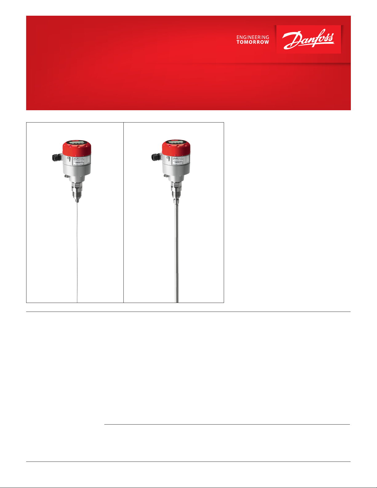
Liquid Level Sensor
Type AKS 4100U
AKS 4100U - Coaxial VersionAKS 4100U - Cable Version
The AKS 4100U liquid level sensor is designed specically
to measure liquid levels in awide range of refrigeration
applications.
The AKS 4100U liquid level sensor is based on a proven
techhology called Time Domain Reectometry (TDR) or
Guided Micro Wave.
AKS 4100U liquid level sensor can be used to measure
the liquid level of many dierent refrigerants in vessels,
accumulators, receivers, standpipes, etc.
The electrical output is a 2-wired, loop powered
4 – 20 mA output signal, which is proportional to the
refrigerant liquid level.
AKS 4100U in a cable version is suitable for HCFC, Non
ammable HFC and R717 (Ammonia), and diering
lengths from 800 mm / 31.5 in. and up to 5000 mm /
197 in..
The coaxial version of AKS 4100/4100U is designed for use
with R744 (CO2), HCFC, Non ammable HFC and R717
(Ammonia).
The AKS 4100U coaxial version should always be used for
marine applications for all refrigerant types.
The AKS 4100U cable version should NOT be used for CO2
or marine applications.
Dust, foam, vapour, agitated surfaces, boiling surfaces,
changes in density or in the dielectric constant , εr, for the
liquid have no inuence on the AKS 4100U performance.
Oil accumulated in the bottom of a standpipe will not
disturb the liquid level signal and it is not necessary to
remove AKS 4100U for cleaning after oil has been drained
out of the standpipe.
Features
© Danfoss | DCS (MWA) | 2017.09
y One product covering several probe lengths (cable
version)
y A single product for all commonly used refrigerants
(cable version)
y Cable version requires less top-end clearance for
installation and service
y Proven operation with all refrigerants in combina-
tion with oil.
y No need to clean cable version when fully covered
by oil.
y The cable version is very compact and easy to
handle, ship, install and use with dierent lengths
and refrigerants
y Changes of the liquid dielectric constant (εr) do not
aect operation.
y 5000 mm / 197 in. probe length with cable version
y 2-wire loop powered; no separate transformer
needed.
Please Note:
AKS 4100U can be connected directly to Danfoss
EKE 347 liquid level controller and thus be powered
from EKE 347.
If used together with Danfoss EKC 347 liquid level
controller, a 14 – 30 V DC supply is required.
y Multi language HMI. Level and setting readout in
mm,cm,m (ft, in.)
Language HMI versions:
- English (default), German, French, Spanish
- English (default), Japanese, Chinese Russian
For further details regarding mechanical and electrical installation please refer to the product
installation guides DKRCI.PI.SC0.D (CABLE version), DKRCI.PI.SC0.E (COAXIAL D14 version) and
DKRCI.PI.SC0.H1/DKRCI.PI.SC0.J1 (COAXIAL D22 version).
DKRCI.PD.SC0.F1.22 | 520H5916 | 1
Page 2

Data sheet | Liquid Level Sensor, type AKS 4100U
Contents Page
Features ................................................................................................................................................................................................. 1
Product concept
CABLE version .............................................................................................................................................................................. 3
Cable version ................................................................................................................................................................................ 3
Optional HMI ....................................................................................................................................................................................... 5
Measuring principle ......................................................................................................................................................................... 6
Main technical data ........................................................................................................................................................................... 6
Measuring range:
CABLE version .............................................................................................................................................................................. 7
COAXIAL D14 version ................................................................................................................................................................ 8
COAXIAL D22 version ................................................................................................................................................................ 8
Ordering AKS 4100U ......................................................................................................................................................................... 9
Dimensions and weights ...............................................................................................................................................................10
Technical data ................................................................................................................................................................................... 11
Quick setup:
CABLE version ............................................................................................................................................................................ 13
COAXIAL version .......................................................................................................................................................................14
Forcing mA output ..........................................................................................................................................................................16
Entering refrigerant dielectric gas constant ..........................................................................................................................17
Saturated vapour dielectric constant .......................................................................................................................................18
How to change the language setting (Default: English)....................................................................................................19
Reset to factory setting ..................................................................................................................................................................19
© Danfoss | DCS (MWA) | 2017.09
DKRCI.PD.SC0.F1.22 | 520H5916 | 2
Page 3
Data sheet | Liquid Level Sensor, type AKS 4100U
Product concept
AKS 4100U is available
in two dierent versions:
y Cable version
y Coaxial version
CABLE version: COAXIAL D14 version
(14 mm / 0.55 in. tube diameter):
Both Cable and Coaxial versions are available with
mechanical process connection:
y AKS 4100U: ¾ in. NPT
COAXIAL D22 version
(22 mm / 0.87 in. tube diameter):
D22 marking
Cable version
© Danfoss | DCS (MWA) | 2017.09
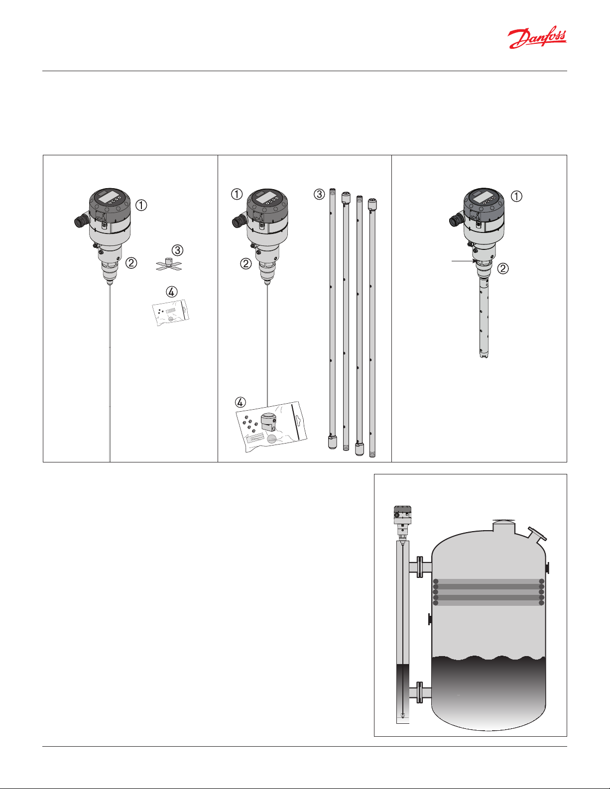
Cable version
The cable version consists of:
Signal converter, which can be supplied
with or without HMI
Mechanical process connection with
5 m / 197 in. ø2 mm / 0.08 stainless cable
Counterweight
Accessory bag comprising:
3 mm set screws
Red cover to protect mechanical process
connection prior to mounting signal
converter.
Setting label.
With the cable version it is possible to adapt the
AKS 4100U to any possible length in the range of
800 mm / 31.5 in. to 5000 mm / 196.9 in.
Cable version can be used in R717 / NH3, HCFC and
HFC (εr, liquid > 5.6).
AKS 4100U cable version must ALWAYS be
installed in a level column 2 in. to 4 in. in size.
DKRCI.PD.SC0.F1.22 | 520H5916 | 3
Page 4
Data sheet | Liquid Level Sensor, type AKS 4100U
Coaxial version
Coaxial D14 version (see page 3)
The Coaxial version consists of:
Signal Converter (with or without HMI)
Mechanical process connection with
5 m / 197 in., Ø2 mm / 0.08 stainless
wire
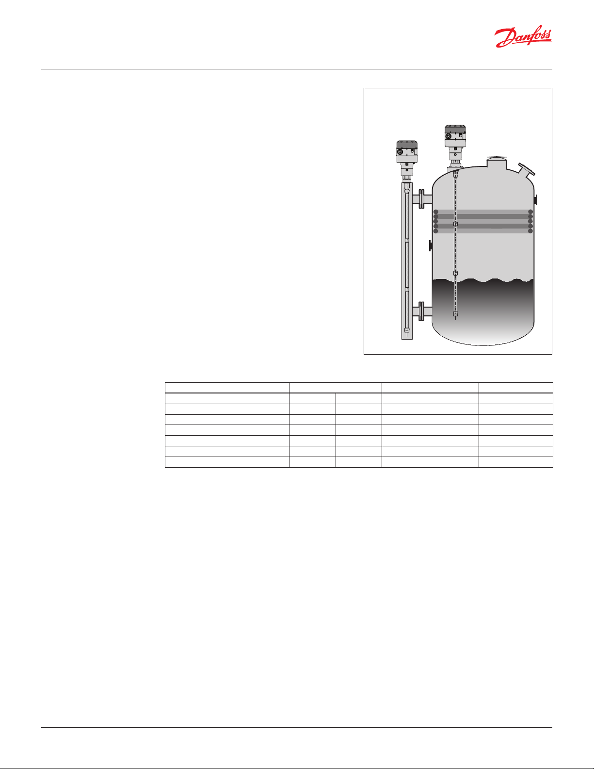
AKS 4100U, Coaxial can be installed in a
level column (a) or directly in a vessel (b).
b
a
Tube(s) depending on required length
Accessory bag comprising:
End Connector (incl. 3 mm / 0.12 in.
set screws.)
3 mm / 0.12 in. set crews (1 set screw pr. tube)
Red cover to protect mechanical process
connection , before Signal Converter
is mounted.
Setting label.
Coaxial D22 version (see page 3)
The Coaxial D22 version consists of:
Signal Converter (with or without HMI)
Mechanical process connection 280 mm /
11 in.. 8 mm / 0.3 in. inner rod.
The coaxial version is mandatory for use in:
- R744 / CO2 (εr, liquid > 1.3).
- Marine applications
The coaxial version can also be used in the refrigerants:
R717 / NH3, HCFC and HFC.
The coaxial version is available
in the following probe lengths:
Danfoss type Tube diameter Type selection in HMI Thread
AKS 4100U, 11.0 in. 22 mm 0.87 in. D22 ¾ in. NPT
AKS 4100U, 19.2 in. 14 mm 0.55 in. D14 ¾ in. NPT
AKS 4100U, 30 in. 14 mm 0.55 in. D14 ¾ in. NPT
AKS 4100U, 45 in. 14 mm 0.55 in. D14 ¾ in. NPT
AKS 4100U, 55 in. 14 mm 0.55 in. D14 ¾ in. NPT
AKS 4100U, 65 in. 14 mm 0.55 in. D14 ¾ in. NPT
AKS 4100U, 85 in. 14 mm 0.55 in. D14 ¾ in. NPT
© Danfoss | DCS (MWA) | 2017.09
DKRCI.PD.SC0.F1.22 | 520H5916 | 4
Page 5
Data sheet | Liquid Level Sensor, type AKS 4100U
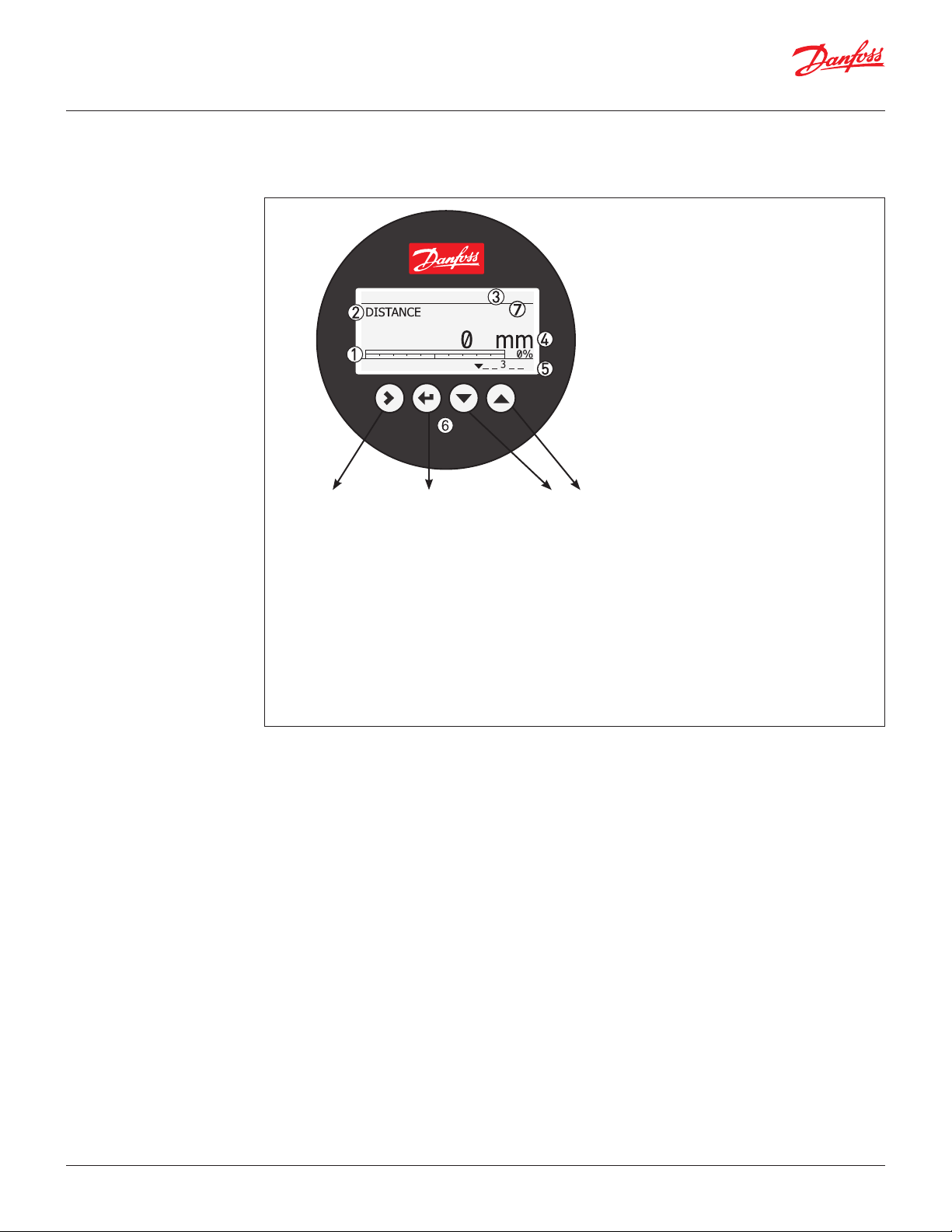
Optional HMI
The optional HMI Service/Display unit is used for
commissioning and quick on-site setup and is easily
mounted on the AKS 4100U.
Enter menu system
Enter QUICK SETUP
AKS 4100
Unit change at
distance/level
readout:
m, cm, mm, in, ft
*
Change between:
Distance*
Level**
Output (%)***
Output (mA)****
* DISTANCE is a display option.
If the display is set to “DISTANCE” the displayed
value will be the distance from the Reference
point to the top surface of the liquid
refrigerant (see pages 7 and 8).
** LEVEL is display option.
If the display is set to “LEVEL” then the value
displayed will be:
PROBE LENGTH (entered in QUICK SETUP)
– DISTANCE (see pages 7 and 8)
The service unit supports mulitple languages in
both SI and US units.
4 – 20 mA output displayed as bar graph
and in percentage [%]
Measurement name (in this example,
DISTANCE)
Device tag name
Measurement reading and unit
Device status (markers)
Marker 1, 2 and 3 (Error)
Hardware problem; the Signal Converter
hardware is defective. Contact Danfoss.
Marker 4 and 5 (Notication)
Depending on the level, the marker is ON
or OFF. Used for Danfoss service
information only.
Keypad buttons
Flashing star indicating unit in operation.
*** OUTPUT (%) is display option.
Will represent the level of refrigerant,in
percent, scaled (entered in QUICK SETUP)
according to: SCALE 4 mA (0%), SCALE
20 mA (100%) (see pages 7 and 8).
**** OUTPUT I (mA) is display option.
Will represent the level of refrigerant,
in 4 – 20 milliampere, scaled (entered in QUICK SETUP)
according to: SCALE 4 mA
(4 mA), SCALE 20 mA (20 mA) (see pages 7 and 8).
© Danfoss | DCS (MWA) | 2017.09
DKRCI.PD.SC0.F1.22 | 520H5916 | 5
Page 6
Data sheet | Liquid Level Sensor, type AKS 4100U
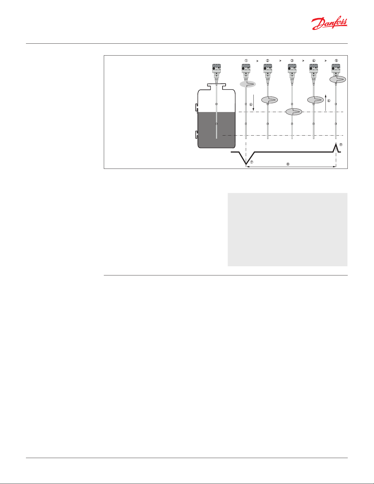
Measuring principle
(Cable and Coaxial)
1. The electromagnetic (EM) pulse is
transmitted by the signal converter
2. The pulse goes down the probe
at the speed of light in air, V1
3. The pulse is reected
4. The pulse goes up the probe at
speed, V1
5. The converter receives the pulse
and records the signal
6. The EM pulse moves at speed, V1
7. Transmitted EM pulse
8. Half of this time is equivalent
to the distance from the
reference point of the device
(the ange facing) to the surface
of the product
9. Received EM pulse
The AKS 4100U electronic converter emits lowintensity, high frequency electromagnetic pulses
with a width of approximately 1 nanosecond, which
travel at the speed of light along the probe (wire or
coaxial cable) down to the liquid surface.
The pulses are reected by the liquid surface, guided
back along the probe, and received and analysed
by the AKS 4100U electronic converter and then
converted into a liquid level reading. This method is
called time domain reectometry (TDR) or guided
microwave.
The dielectric constant, εr, of the liquid is a key
parameter and has a direct impact on the degree
of reection of the high frequency electromagnetic
pulses. Liquids with high εr values, such as ammonia,
produce strong reections, while liquids with low εr
values, such as CO2, produce weak reections.
As long as the εr value of the liquid refrigerant is
higher than 1.2, AKS 4100U can detect the liquid level
and level measurement accuracy is not aected.
If the temperature condition in the standpipe/vessel
is known, a constant (dielectric constant of the
refrigerant gas) can be entered (parameter 2.5.3 GAS
EPS.R), in order to obtain improved Top and Bottom
Dead Zone values.
Refer to pages 7 to 8 for Measuring range of AKS
4100U - CABLE version and COAXIAL version.
For details of gas constant values for dierent
temperatures and refrigerants plus the procedure
for
entering these via the HMI, refer to pages 17 to 18.
Main technical data
(see a complete list of all
technical data on page 11)
1
) AKS 4100U Coaxial 11 in are only
released for R717/NH
3
Supply Voltage
14 – 30 V DC. Min / Max. Value for an output of 22 mA
at the terminal.
Ambient temperature supply voltage limitations:
-40 – 80 °C / -40 – 176 °F : 16 – 30 V DC
-20 – 80 °C /-4 – 176 °F : 14 – 30 V DC
Load
RL [Ω] ≤ ((Uext -14 V) / 20 mA).
– Default (Error output set to 3.6 mA)
RL [Ω] ≤ ((Uext -14 V) / 22 mA).
– (Error output set to 22 mA)
Cable gland
AKS 4100 PG 13, M20×1.5 ;
(cable diameter: 6 – 8 mm / 0.24 – 0.31in.
AKS 4100U ½ in. NPT
Refrigerant temperature
-60 – 100 °C / -76 – 212 °F
Ambient temperature
-40 – 80 °C / -40 – 176 °F
For HMI : -20 – 60 °C / -4 – 140 °F
Process pressure
-1 – 100 barg / -14.5 – 1450 psig
Terminals (spring loaded)
0.5 – 1.5 mm² (~20-15 AWG)
Enclosure:
IP 66/67 (~NEMA type 4X)
Mechanical connection
Cable version / Coaxial version:
AKS 4100U: ¾ in. NPT
Refrigerants 1)
The listed refrigerants are qualied and approved by
Danfoss
R717 / NH3 -40 – 50 °C / -40 – 122 °F
R744 / CO2 -50 – 15 °C / -58 – 59 °F
HCFC: R22 -50 – 48 °C / -58 – 118 °F
HFC: R404A -50 – 15 °C / -58 – 59 °F
R410A -50 – 15 °C / -58 – 59 °F
R134A -40 – 50 °C / -40 – 122 °F
The listed refrigerants may be used in the complete
temperature range of AKS 4100U, however, the
accuracy may be aected if the above listed
temperature range is exceeded.
Other refrigerants within the groups of HCFC and
HFC can be detected and measured if the following
conditions are fullled:
Reference conditions
Dielectric constant
Cable version can be used in R717 / NH3, HCFC and HFC
(εr, liquid > 5.6 ).
The coaxial version is mandatory for use in:
- R744 / CO2 (εr, liquid > 1.3).
- Marine applications.
The coaxial version can also be used in the refrigerants:
R717 / NH3, HCFC and HFC.
© Danfoss | DCS (MWA) | 2017.09
DKRCI.PD.SC0.F1.22 | 520H5916 | 6
Page 7

Data sheet | Liquid Level Sensor, type AKS 4100U
Top dead zones
120 mm / 4.7 in.
Measuring range
Bottom dead zone (see tables)
Counterweight: 33 mm / 1.3 in.
Min: 20 mm / 0.8 in.
Steel wire
insertion length:
12 mm / 0.5 in.
Probe length*
4 mA (0 %)*
Inner length of the standpipe
Danfoss
M84H0017_1
20 mA
(100 %)*
Reference point
Distance
Surface level
Standpipe
diameter: 2 – 4 in.
Measuring range of AKS 4100U - CABLE version
Bottom deadzone values based on the factory setting
of dielectric constant
Refrigerant Probe length range Bottom dead
[mm] [in.] [mm] [in.]
800 31.5 115 4.2
801 – 999 31.5 – 39 120 4.7
Ammonia,
HFC, HCFC
1000 – 1999 39 – 79 150 5.9
2000 – 2999 79 – 118 180 7.1
3000 – 3999 118 – 157 210 8.3
4000 – 5000 157 – 197 240 9.4
Improved Bottom dead zone values after the
adjustment of dielectric constant
Refrigerant Probe length range Bottom dead
[mm] [in.] [mm] [in.]
Ammonia,
HFC, HCFC
800 – 5000 31.5 – 197 90 3.5
zone
zone
* Values to be entered into HMI Quick Setup menu
and recorded on the setting label.
Stick the setting label onto the Signal Converter either
inside or outside.
© Danfoss | DCS (MWA) | 2017.09
DKRCI.PD.SC0.F1.22 | 520H5916 | 7
Page 8

Data sheet | Liquid Level Sensor, type AKS 4100U
Top
dead
zone
120 mm /
4.7 in.
Measuring range
Bottom
dead
zone
(see tables)
Min: 30 mm / 1.2 in.
Ø2 mm / 0.08 in.
stainless wire
Probe length*
4 mA (0 %)*
Inner length of the stand pipe
Danfoss
M84H0026_1
20 mA
(100 %)*
Reference point
Distance
Surface level
Measuring range
Bottom dead z
(see tables)
Inner length of the stand pipe
Min: 30 mm / 1.2 in.
Measuring range of AKS 4100U - COAXIAL D14 version
Please note: It is mandatory to
input dielectric constant for CO2
applications.
AKS 4100U
Dielectric Constant εr always set during Quick
Setup
Refrigerant
CO
2
Factory setting
Refrigerant
Ammonia
Improved Bottom dead zone values
after the adjustment of dielectric constant
Refrigerant
Ammonia
Factory setting
Refrigerant
HCFC,HFC
Improved Bottom dead zone values
after the adjustment of dielectric constant
Refrigerant
HCFC,HFC
Bottom
Probe
Dead
Length
Zone
[in.] [i n.] [mm]
19.2
30
45
6.7 170
55
65
85
Bottom
Probe
Dead
Length
Zone
[in.] [i n.] [mm]
19.2 3.73 95
30 4.05 103
45 4.50 114
55 4.80 12 2
65 5 .10 13 0
85 5.70 145
Bottom
Probe
Dead
Length
Zone
[in.] [i n.] [mm]
19.2
30
45
3.1 80
55
65
85
Bottom
Probe
Dead
Length
Zone
[in.] [i n.] [mm]
19.2 4.52 115
30 4.84 12 3
45 5.29 134
55 5. 59 142
65 5.89 150
85 6.49 165
Bottom
Probe
Dead
Length
Zone
[in.] [i n.] [mm]
19.2
30
45
3.94 10 0
55
65
85
Bottom
Dead
Zone
Bottom
Dead
Zone
Bottom
Dead
Zone
Bottom
Dead
Zone
Bottom
Dead
Zone
* Values to be entered into HMI Quick Setup menu
and recorded on the setting label.
Stick the setting label onto the Signal Converter either
inside or outside.
Measuring range of AKS 4100U - COAXIAL D22 version
AKS 4100U
Factory setting
Refrigerant
Ammonia 11. 0 1.9 48
Improved Bottom dead zone values
after the adjustment of dielectric constant
Refrigerant
Ammonia 11. 0 1.6 40
* Values to be entered into HMI Quick Setup menu and recorded on the setting label.
Stick the setting label onto the Signal Converter either inside or outside.
© Danfoss | DCS (MWA) | 2017.09
Probe
Length
[in.] [i n.] [mm]
Probe
Length
[in.] [i n.] [mm]
Bottom
Dead
Zone
Bottom
Dead
Zone
Bottom
Dead
Zone
Bottom
Dead
Zone
Top dead zone
60 mm / 2.4 in.
one
Reference point
20 mA
(100 %)*
Distance
Probe length*
Surface level
4 mA (0 %)*
DKRCI.PD.SC0.F1.22 | 520H5916 | 8
Page 9

Data sheet | Liquid Level Sensor, type AKS 4100U
Ordering AKS 4100U
Cable version - AKS 4100U
Description Code number
AKS 4100U with 196 in. insertion cable length which can be trimmed to desired length during
installation
Coaxial version - 4100U (available in predened lengths)
D14 D22
Description Probe length Code number
AKS 4100U - Coaxial D22 version with ¾ in. NPT process connection 1) 11 084H4536
AKS 4100U - Coaxial D14 version with ¾ in. NPT process connection 19.2 084H4530
AKS 4100U - Coaxial D14 version with ¾ in. NPT process connection 30 084H4531
AKS 4100U - Coaxial D14 version with ¾ in. NPT process connection 45 084H4532
AKS 4100U - Coaxial D14 version with ¾ in. NPT process connection 55 084H4533
AKS 4100U - Coaxial D14 version with ¾ in. NPT process connection 65 084H4534
AKS 4100U - Coaxial D14 version with ¾ in. NPT process connection 85 084H4535
1
) AKS 4100U Coaxial 11 in. are only released for R717/NH
with HMI
084H4521
mm in.
3
with HMI
Accessories
Description Code number
AKS 4100U HMI Display 084H4548
AKS 4100U Signal Converter + Metaglass with HMI, excluding cable gland 084H4555
AKS 4100U converter connecting cable (5 pcs.) 084H4557
Service kits
Description Content Code number
Cable and counterweight for
AKS 4100U - CABLE version
End connector incl screws for
AKS 4100U - COAXIAL D14 version
Process connection, counterweight and
5 m / 197 in., Ø2 mm / Ø0.08 in. cable for AKS
4100U - CABLE and COAXIAL D14 version
Other spare parts
Description Code number
AKS 4100U Coaxial tube. Tube length : 680 mm / 26.8 in. 084H4543
AKS 4100U blank top cover for signal converter 084H4544
Process connection
AKS 4100U - Coaxial D22 - ¾ in. NPT – 11 in.
Cable - 5 m / 197 in., Ø2 mm / Ø0.08 in.
084H4542Crimp
Counterweight
End connector (incl. 3 mm / 0.12 in set screws) 084H4549
¾ in. NPT process connection
Counterweight
084H4546
084H4552
© Danfoss | DCS (MWA) | 2017.09
DKRCI.PD.SC0.F1.22 | 520H5916 | 9
Page 10

Data sheet | Liquid Level Sensor, type AKS 4100U
Ø104 mm / Ø4.1 in.
1.4 in.
Ø104 mm / Ø4.1 in.
1.4 in.
Ø 104 mm / Ø 4.1 in.
/
Dimensions and weights
CABLE version
Ø22 mm /
Ø0.9 in.
COAXIAL D14 version
177.5 mm / 7 in. 34.2 mm /
177.5 mm / 7 in. 34.2 mm /
Ø14 mm /
Ø0.6 in.
Ø2 mm /
Ø0.08 in.
Probe length
Probe length
Ø92 mm / Ø3.6 in.
33 mm /
1.3 in.
Weight: approx. 2.3 kg / 5.1 lbs
Ø21 mm /
Ø0.8 in.
Weight: approx. 3.5 kg / 8.4 lbs
COAXIAL D22 version
© Danfoss | DCS (MWA) | 2017.09
177.5 mm / 7 in.
0.8 in.
21.1 mm
34.2 mm /
1.4 in.
Probe length
Weight: 2.4 kg / 5.3 lbs
DKRCI.PD.SC0.F1.22 | 520H5916 | 10
Page 11

Data sheet | Liquid Level Sensor, type AKS 4100U
Technical data
Measuring system
Measuring principle 2-wire loop-powered level transmitter; Time Domain Reectometry (TDR )
Application range Level measurement of liquid refrigerants.
Primary measured value Time between the emitted and received signal
Secondary measured value Distance or level
Approved refrigerants:
Halogen Free / Environmently friendly: R717 / NH3, R744 / CO
HCFC and non ammable HFC.
2
Design
Options Probe types
Insertions (probe) length Coaxial D14
Dead zone This depends on the type of probe. (see pages 7 and 8)
Cable
Mechanical process connection with 5 m / 197 in., Ø2 mm / 0.08 in. stainless cable:
Mechanical thread on the mechanical process connection
AKS 4100U: ¾ in. NPT
Coaxial D14
Mechanical process connection with 5 m / 197 in., Ø2 mm / 0.08 in. stainless cable
and 14 mm / 0.55 in. outer stainless tube:
Mechanical thread on the mechanical process connection
AKS 4100U: ¾ in. NPT
Stainless steel tubes supporting the available probe length
Coaxial D22
Mechanical process connection with in 22 mm / 0.87 in. outer stainless tube.
8 mm / 0.3 in. inner rod.
Mechanical thread on the mechanical process connection
AKS 4100U: ¾ in. NPT
LCD display
AKS 4100U: 19.2, 30, 45, 55, 65, 85 in.
Coaxial D22
AKS 4100U: 11.0 in.
Single cable Ø2 mm / 0.08 in.: 800 – 5000 mm / 31.5 – 197 in.
Display and User interface
Display Integrated LCD display
128 × 64 pixels in 8-step greyscale with 4-button keypad
Interface languages English (default), German, French, Spanish, Japanese, Chinese, Russian
Operating conditions
Temperature:
Ambient temperature -40 – 80 °C / -40 – 175 °F
Storage temperature -40…85 °C / -40…185 °F
Process connection temperature Standard
Pressure:
Operating pressure Standard:
Other conditions:
Liquid dielectric constant (εr) Cable version to be used in R717 / NH3, HCFC and HFC
Vibration resistance EN 60721-3-4 (1...9 Hz: 3 mm / 10...200 Hz:1g; 10g shock half-wave sinusoidal: 11 ms)
Protection category IP 66/67 equivalent to NEMA type 4X (housing) and type 6P (probe)
For HMI : -20 – 60 °C / -4 – 140 °F
-60 – 100 °C / -76 – 212 °F
-1 – 100 barg / -14.5 – 1450 psig
εr, liquid > 5.6
Coaxial version is mandatory in R744 / CO2
εr, liquid > 1.3
Installation conditions
Dimensions and weights See pages 10 and 11
© Danfoss | DCS (MWA) | 2017.09
DKRCI.PD.SC0.F1.22 | 520H5916 | 11
Page 12

Data sheet | Liquid Level Sensor, type AKS 4100U
Technical data
(continued)
Material
Housing Aluminium
Coaxial D14 and D22 version Standard: Stainless steel (1.4404 / 316L)
Single cable Standard: Stainless steel (1.4401 / 316)
Process tting Standard: Stainless steel (1.4404 / 316L)
Gaskets EPDM (-50...150 °C / -58...300 °F)
Cable gland Plastic (black)
Process connections
Thread:
Single cable Ø2 mm / 0.08¨ AKS 4100U: ¾ in. NPT
Coaxial D14 and D22 version AKS 4100U: ¾ in. NPT
Electrical connections
Power supply Terminals output:
14 – 30 V DC. Min. / Max. Value for an output of 22 mA at the terminal.
Ambient temperature limitations:
-40 – 80 °C / -40 – 176 °F : 16 – 30 V DC
-20 – 80 °C /-4 – 176 °F : 14 – 30 V DC
Current output load RL [Ω] ≤ ((Uext -14 V) / 20 mA).
– Default (Error output set to 3.6 mA)
RL [Ω] ≤ ((Uext -14 V) / 22 mA).
– (Error output set to 22 mA)
Cable gland AKS 4100: PG 13, M20×1.5 ; (cable diameter: 6 – 8 mm / 0.24 – 0.31 in.)
AKS 4100U: ½ in. NPT
Cable entry capacity (terminal) 0.5 – 1.5 mm2 (~20-15 AWG)
Input and output
Current output:
Output signal 4…20 mA or 3.8…20.5 mA acc. to NAMUR NE 43
Resolution ±3 μA
Temperature drift Typically 75 ppm/K
Error signal High: 22 mA; Low: 3.6 mA acc. to NAMUR NE 43; Hold (frozen value - not available
with NAMURNE 43 compliant output.
Approvals and certication
This device fulls the statutory requirements of the EMC directives. The manufacturer certies successful testing of the product
by applying the CE mark.
Other standards and approvals:
EMC EMC Directives 2004 / 108 / EC and 93 / 68 / EEC in conjunction with
LVD Low-Voltage Directives 2006 / 95 / EC and 93 / 68 / EEC in conjunction with
NAMUR NAMUR NE 21 Electromagnetic Compatibility (EMC) of Industrial Process and
EN 61326-1 (2006) and EN 61326-2-3 (2006). The device conforms to these standards if :
- the device has a coaxial probe or
- the device has a single probe that is installed in a metallic tank.
EN 61010-1 (2001)
Laboratory Control Equipment
NAMUR NE 43 Standardization of the Signal Level for the Failure Information of
Digital Transmitters
© Danfoss | DCS (MWA) | 2017.09
DKRCI.PD.SC0.F1.22 | 520H5916 | 12
Page 13

Data sheet | Liquid Level Sensor, type AKS 4100U
DISTANCE
AKS 4100
AKS 4100
QUICK SETUP ?
AKS 4100
SINGLE CABLE 5000 mm
(0%) 4 mA
4877 mm
(100%) 20 mA 120 mm
Power supply U [VDC]
Current output load R
[Ω ]
Technical data
(continued)
Minimum power supply voltage
Use this graph to nd the minimum power supply voltage for a given current output load:
L
Minimum power supply voltage for an output of 22mA at the terminal
Note:
The signal converter can be programmed with or without mechanical process connector assembled.
Quick Setup (all values below are only examples)
• Connect the device to the power supply
(see the section "Electrical installation/
connection".
• Press 3 times.
AKS 4100
QUICK SETUP ?
QUICK SETUP ?
YES NO
• Press to change of SCALE 4 mA.
Press to change the cursor position.
Press to decrease the value or to
increase the value.
Press to conrm.
AKS 4100
SCALE 20 mA
00070 mm
• Press to conrm.
• Press or to select either
STORE NO or STORE YES.
Press to conrm.
AKS 4100
1.0.0
STORE NO
• Press
PROBE TYPE
SINGLE CABLE
AKS 4100
• Press to change of SCALE 20 mA.
Press to change the cursor position.
Default screen appears:
AKS 4100
5000 mm
Press to decrease the value or to
• Press or to select between SINGLE,
COAXIAL D14 and COAXIAL D22.
Choose SINGLE and press to conrm.
AKS 4100
PROBE LENGTH
05000 mm
• Press to change the PROBE LENGTH.
Press to change the position of the
cursor.
Press to decrease the value or to
increase the value.
increase the value.
Press to conrm.
AKS 4100
QUICK SETUP
COM PLETED IN 8
• Wait for QUICK SETUP to complete
8-second timeout
AKS 4100
1.0.0
QUICK START
Quick Setup completed
You have the possibility of checking
your settings by pressing twice.
Press
default screen.
to return to
Press to conrm.
SCALE 4 mA
AKS 4100
04946 mm
© Danfoss | DCS (MWA) | 2017.09
DKRCI.PD.SC0.F1.22 | 520H5916 | 13
Page 14

Data sheet | Liquid Level Sensor, type AKS 4100U
PROBE TYPE
SINGLE
AKS 4100
GAS EPS R ?
001.000
AKS 4100
LIQUID CO2 ?
YES NO
AKS 4100
QUICK SETUP ?
AKS 4100
COAX IAL 2200 mm
(0 %) 4 mA 1900 mm
(100 %) 20 mA 70 mm
Note: The signal converter can be programmed with or without mechanical process connector assembled.
Quick Setup (all values below are only examples)
When CO2 is used:
• Connect the device to the power supply
(see the section "Electrical installation/
connection").
• Press 3 times.
AKS 4100
QUICK SETUP ?
YES NO
• Press
AKS 4100
CABLE
• Press or to select between SINGLE,
COAXIAL D14 and COAXIAL D22. Choose
COAXIAL D14 and press to conrm.
• Press (YES) to conrm
• Press to conrm.
AKS 4100
PROBE LENGTH
05000 mm
• Press to change the PROBE LENGTH.
Press to change the position of the
cursor.
Press to decrease the value or to
increase the value.
Press to conrm.
AKS 4100
SCALE 4 mA
04946 mm
• Press to change of SCALE 4 mA.
Press to change the cursor position.
Press to decrease the value or to
increase the value.
Press to conrm.
AKS 4100
SCALE 20 mA
00070 mm
COM PLETED IN 8
• Wait for QUICK SETUP to complete.
Count down from 8 sec.
• Press to conrm.
• Press or to select between
STORE NO or STORE YES.
Press to conrm.
Default screen appears:
DISTANCE
AKS 4100
QUICK SETUP
AKS 4100
1.0.0
QUICK START
AKS 4100
1.0.0
STORE NO
AKS 4100
5000 mm
• Press to change GAS EPS.R.
(Select the correct value from the tables
on page 8)
Press to change cursor position.
Press to decrease the value or to
increase the value.
• Press to change of SCALE 20 mA.
Press to change the cursor position.
Press to decrease the value or to
increase the value.
Press to conrm.
Quick Setup completed
You have the possibility of checking
your settings by pressing twice.
D14
Press
to return to
default screen.
© Danfoss | DCS (MWA) | 2017.09
DKRCI.PD.SC0.F1.22 | 520H5916 | 14
Page 15

Data sheet | Liquid Level Sensor, type AKS 4100U
PROBE TYPE
SINGLE
AKS 4100
LIQUID CO2 ?
YES NO
SCALE
SCALE
PROBE
AKS 4100
QUICK SETUP ?
For all other refrigerants (please note that Coaxial D22 version can only be used in R717/NH3):
• Connect the device to the power supply
(see the section "Electrical installation/
connection").
• Press 3 times.
AKS 4100
QUICK SETUP ?
YES NO
• Press
AKS 4100
CABLE
• Press or to select between SINGLE,
COAXIAL D14 and COAXIAL D22. Choose
the coaxial version you have (see page 3
for dierence) and press to conrm.
• Press to change the PROBE LENGTH.
Press to change the position of the
cursor.
Press to decrease the value or to
increase the value.
Press to conrm.
AKS 4100
4 mA
04946 mm
• Press to change of SCALE 4 mA.
Press to change the cursor position.
Press to decrease the value or to
increase the value.
Press to conrm.
AKS 4100
20 mA
00070 mm
AKS 4100
QUICK SETUP
COM PLETED IN 8
• Wait for QUICK SETUP to complete.
Count down from 8 sec.
AKS 4100
1.0.0
QUICK START
• Press to conrm.
AKS 4100
1.0.0
STORE NO
• Press or to select between
STORE NO or STORE YES.
Press to conrm.
• Press (NO) to conrm
AKS 4100
LENGTH
05000 mm
• Press to change of SCALE 20 mA.
Press to change the cursor position.
Press to decrease the value or to
increase the value.
Press to conrm.
Default screen appears:
AKS 4100
DISTANCE
5000 mm
Quick Setup completed
© Danfoss | DCS (MWA) | 2017.09
DKRCI.PD.SC0.F1.22 | 520H5916 | 15
Page 16

Data sheet | Liquid Level Sensor, type AKS 4100U
DISTANCE
AKS 4100
QUICK SETUP ?
CABLE and COAXIAL version
Forcing mA output (all values below are only examples)
Default screen
DISTANCE
AKS 4100
5000 mm
• Press
AKS 4100
1.0.0
QUICK START
• Press
AKS 4100
2.0.0
SUPERVISOR
• Press
AKS 4100
2.0.0
__________
Enter password:
AKS 4100
2.1.0
INFORMATION
• Press
AKS 4100
2.2.0
TESTS
• Press
AKS 4100
2.2.1
SET OUTPUT
• Press
AKS 4100
SET OUTPUT
3.5 mA
• Press to decrease the value or to
increase the value.
Press to conrm.
AKS 4100
SET OUTPUT
8 mA
• Press 4 times to return to default
screen.
Default screen appears:
AKS 4100
5000 mm
Force mA completed and disabled
© Danfoss | DCS (MWA) | 2017.09
DKRCI.PD.SC0.F1.22 | 520H5916 | 16
Page 17

Data sheet | Liquid Level Sensor, type AKS 4100U
DISTANCE
DISTANCE
AKS 4100
QUICK SETUP ?
Optional Procedure
If the temperature condition in the stand pipe is known, a constant (dielectric constant of the refrigerant gas) can be entered
(parameter 2.5.3 GAS EPS.R), in order to obtain lower Top and Bottom Dead Zone values (see pages 7 and 8).
Entering refrigerant dielectric gas constant (all values below are only examples)
Default screen
AKS 4100
5000 mm
• Press
AKS 4100
1.0.0
QUICK START
• Press
AKS 4100
2.0.0
SUPERVISOR
• Press
AKS 4100
2.0.0
__________
Enter password:
AKS 4100
2.1.0
INFORMATION
• Press 4 times.
AKS 4100
2.5.0
APLICATI ON
• Press
AKS 4100
2.5.1
TRACING VEL .
• Press 2 times.
AKS 4100
2.5.3
GAS EPS. R
• Press to change GAS EPS.R.
(Select the correct value from the tables
on page 16)
Press to change cursor position.
Press to decrease the value or to
increase the value.
AKS 4100
GAS EPS. R
1.066
• Press to conrm.
AKS 4100
2.5.3
GAS EPS. R
• Press 3 times.
AKS 4100
1.0.0
STORE NO
• Press or to select between
STORE NO or STORE YES.
Select STORE YES by pressing
Default screen appears:
AKS 4100
5000 mm
Entering the dielectric constant of
refrigerant gas completed
© Danfoss | DCS (MWA) | 2017.09
DKRCI.PD.SC0.F1.22 | 520H5916 | 17
Page 18

Data sheet | Liquid Level Sensor, type AKS 4100U
Saturated vapour dielectric constant (default value: 1.066)
R717 (NH3)
Temperature range:
-60 – 50 °C / -76 – 122 °F
Temperature
[°C]
-60 – -42 -76 – -43 1.00
-41 – -18 42 – 0 1.01
-17 – -5 1 – 23 1.02
-4 – 4 24 – 39 1.03
5 – 12 40 – 54 1.04
13 – 18 55 – 64 1.05
19 – 24 65 – 75 1.06
25 – 28 76 – 82 1.07
29 – 33 83 – 91 1.08
34 – 37 92 – 99 1.09
38 – 40 100 – 104 1.10
41 – 44 105 – 111 1.11
45 – 47 112 – 117 1.12
48 – 50 118 – 122 1.13
Temperature
[°F]
R22
Temperature range:
-60 – 48 °C / -76 – 118 °F
Temperature
[°C]
-60 – -50 -76 – -58 1.00
-49 – -25 57 – -13 1.01
-24 – -10 -12 – 14 1.02
-9 – 0 15 – 32 1.03
1 – 8 33 – 46 1.04
9 – 15 47 – 59 1.05
16 – 21 60 – 70 1.06
22 – 26 71 – 79 1.07
27 – 31 80 – 88 1.08
32 – 35 89 – 95 1.09
36 – 39 96 – 102 1.10
40 – 42 103 – 108 1.11
43 – 45 109 – 113 1.12
46 – 48 114 – 118 1.13
Temperature
[°F]
Dielectric constant
of refrigerant gas
Parameter 2.5.3
GAS EPS.R
Dielectric constant
of refrigerant gas
Parameter 2.5.3
GAS EPS.R
R134a
Temperature range:
-60 – 50 °C / -76 – 122 °F
Temperature
[°C]
-60 – -42 -76 – -43 1.00
-41 – -18 -42 – -0 1.01
-17 – -4 1 – 25 1.02
-3 – 5 26 – 41 1.03
6 – 13 42 – 56 1.04
14 – 20 57 – 68 1.05
21 – 25 69 – 77 1.06
26 – 30 78 – 86 1.07
31 – 34 87 – 94 1.08
35 – 38 95 – 100 1.09
39 – 42 101 – 108 1.10
43 – 45 109 – 113 1.11
46 – 48 114 – 119 1.12
49 – 50 120 – 122 1.13
Temperature
[°F]
R404A
Temperature range:
-60 – 15 °C / -76 – 59 °F
Temperature
[°C]
-60 – -47 -76 – -52 1.01
-46 – -35 -51 – -31 1.02
-34 – -26 -30 – -14 1.03
-25 – -19 -13 – -2 1.04
-18 – -14 -1 – 7 1.05
-13 – -9 8 – 16 1.06
-8 – -4 17 – 25 1.07
-3 – 0 26 – 32 1.08
1 – 3 33 – 38 1.09
4 – 6 39 – 43 1.10
7 – 9 44 – 49 1.11
10 – 12 50 – 54 1.12
13 – 15 55 – 59 1.13
Temperature
[°F]
Dielectric constant
of refrigerant gas
Parameter 2.5.3
GAS EPS.R
Dielectric constant
of refrigerant gas
Parameter 2.5.3
GAS EPS.R
R410A
Temperature range:
-65 – 15 °C / -85 – 59 °F
Temperature
[°C]
-65 – -47 -85 – -52 1.01
-46 – -35 -51 – -31 1.02
-34 – -26 -30 – -14 1.03
-25 – -19 -13 – -2 1.04
-18 – -13 -1 – 9 1.05
-12 – -8 10 – 18 1.06
-7 – -4 19 – 25 1.07
-3 – 0 26 – 32 1.08
1 – 4 33 – 40 1.09
5 – 7 41 – 45 1.10
8 – 10 46 – 50 1.11
11 – 12 51 – 54 1.12
13 – 15 55 – 59 1.13
Temperature
[°F]
R744 (CO2)
Temperature range:
-56 – 15 °C / -69 – 59 °F
Temperature
[°C]
-56.0 – -42.0 -69 – -43 1.01
-41.0 – -28.0 -42 – -18 1.02
-27.0 – -17.0 -17 – 2 1.03
-16.0 – -9.0 3 – 16 1.04
-8.0 – -3.0 17 – 27 1.05
-2.0 – 2 28 – 36 1.06
3 – 7 37 – 45 1.07
8 – 11 46 – 52 1.08
12 – 14 53 – 58 1.09
15 59 1.10
Temperature
[°F]
Dielectric constant
of refrigerant gas
Parameter 2.5.3
GAS EPS.R
Dielectric constant
of refrigerant gas
Parameter 2.5.3
GAS EPS.R
R507
Temperature range:
-60 – 15 °C / -76 – 59 °F
Temperature
[°C]
-60 – -48 -76 – -54 1.01
-47 – -36 -53 – -32 1.02
-35 – -28 -31 – -18 1.03
-27 – -21 -17 – -6 1.04
-20 – -15 -17 – -5 1.05
-14 – -10 -4 – 14 1.06
-9 – -6 13 – 22 1.07
-5 – -2 23 – 29 1.08
-1 – 2 30 – 36 1.09
3 – 5 37 – 41 1.10
6 – 8 42 – 47 1.11
9 – 11 48 – 52 1.12
12 – 13 53 – 56 1.13
14 – 15 57 – 59 1.14
Temperature
[°F]
Dielectric constant
of refrigerant gas
Parameter 2.5.3
GAS EPS.R
© Danfoss | DCS (MWA) | 2017.09
DKRCI.PD.SC0.F1.22 | 520H5916 | 18
Page 19

Data sheet | Liquid Level Sensor, type AKS 4100U
DISTANCE
AKS 4100
QUICK SETUP ?
AKS 4100
2.7.0
DISPLAY
AKS 4100
2.7.1
LANGUAG E
AKS 4100
LANGUAG E
ENGLISH
AKS 4100
2.7.1
LANGUAG E
AKS 4100
2.0.0
STORE NO
How to change the language setting (Default: English)
Default screen
AKS 4100
DISTANCE
5000 mm
• Press
AKS 4100
1.0.0
QUICK START
• Press
AKS 4100
2.0.0
SUPERVISOR
• Press
AKS 4100
2.0.0
__________
• Go to SUPERVISOR menu (see page 16).
• Go to parameter 2.9.4 Reset Factory.
• Select RESET FACTORY YES
Enter password:
AKS 4100
2.1.0
INFORMATION
• Press 6 times
• Press
• Press
Reset to factory setting
• Press or to see the language
possibilities
Press to conrm.
• Press 3 times
• Press or to select between
STORE NO or STORE YES.
Select STORE YES by pressing
Default screen appears:
AKS 4100
5000 mm
Language setup completed
• Press 3 times to return to default screen.
Factory reset completed.
© Danfoss | DCS (MWA) | 2017.09
DKRCI.PD.SC0.F1.22 | 520H5916 | 19
Page 20

© Danfoss | DCS (MWA) | 2017.09
DKRCI.PD.SC0.F1.22 | 520H5916 | 20
 Loading...