


Data Sheet
Liquid level sensor
Type AKS 4100 and AKS 4100U
Designed specically to measure liquid levels in
a wide range of refrigeration applications
The AKS 4100/4100U liquid level sensor is
designed specically to measure liquid levels in
a wide range of refrigeration applications.
The AKS 4100/4100U liquid level sensor is
based on a proven techhology called Time
Domain Reectometry (TDR) or Guided Micro
Wave.
AKS 4100/4100U liquid level sensor can be
used to measure the liquid level of many
dierent refrigerants in vessels, accumulators,
receivers, standpipes, etc.The electrical output
is a 2-wired, loop powered 4 – 20 mA output
signal, which is proportional to the refrigerant
liquid level.
AKS 4100/4100U in a cable version is suitable
for HCFC, Non ammable HFC and R717
(Ammonia), and diering lengths from 800
mm / 31.5 in. and up to 5000 mm / 197 in.
The coaxial version of AKS 4100/4100U is
designed for use with R744 (CO2), HCFC, Non
ammable HFC and R717 (Ammonia).
The AKS 4100/4100U coaxial version should
always be used for marine applications for all
refrigerant types. The AKS 4100/4100U cable
version should NOT be used for CO2 or marine
applications.
Dust, foam, vapour, agitated surfaces, boiling
surfaces, changes in density or in the dielectric
constant , εr, for the liquid have no inuence on
the AKS 4100/4100U performance.
Oil accumulated in the bottom of a standpipe
will not disturb the liquid level signal and it is
not necessary to remove AKS 4100/4100U for
cleaning after oil has been drained out of the
standpipe.
AI243386442914en-001101

Liquid level sensor, type AKS 4100 and AKS 4100U
Features
• Approved and qualied by Danfoss for refrigeration applications
• One product covering several probe lengths (cable version)
• A single product for all commonly used refrigerants (cable version)
• Cable version requires less top-end clearance for installation and service
• Proven operation with all refrigerants in combination with oil
• No need to clean cable version when fully covered by oil
• The cable version is very compact and easy to handle, ship, install and use with dierent lengths and refrigerants
• Changes of the liquid dielectric constant (εr) do not aect operation
• 5000 mm / 197 in. probe length with cable version
• 2-wire loop powered; no separate transformer needed
• Multi language HMI. Level and setting readout in mm,cm,m (ft, in.)
◦ Language HMI versions:
▪ English (default), German, French, Spanish
▪ English (default),Japanese, Chinese Russian
NOTE:
AKS 4100/4100U can be connected directly to Danfoss EKE 347 liquid level controller and thus be powered from EKE
347.If used together with Danfoss EKC 347 liquid level controller, a 14 – 30 V DC supply is required.
© Danfoss | Climate Solutions | 2021.07 AI243386442914en-001101 | 2

Liquid level sensor, type AKS 4100 and AKS 4100U
Media
Refrigerants
The listed refrigerants are qualied and approved by Danfoss:
(1)
R717 / NH3: -40 / +50 °C / (-40 / +122 °F)
R744 / CO2: -50 / +15 °C / (-58 / +59 °F)
HCFC: R22 -50 / +48 °C / (-58 / +118 °F)
HFC: R404A -50 / +15 °C / (-58 / +59 °F)
R410A -50 / +15 °C / (-58 / +59 °F)
R134A -40 / +50 °C / (-40 / +122 °F)
The listed refrigerants may be used in the complete temperature range of AKS 4100/4100U, however, the accuracy
may be aected if the above listed temperature range is exceeded.
Other refrigerants within the groups of HCFC and HFC can be detected and measured if the following conditions are
fullled:
Reference conditions
Dielectric constant
Cable version can be used in R717 / NH3, HCFC and HFC (εr, liquid > 5.6 ).
The coaxial version is mandatory for use in:
• R744 / CO2 (εr, liquid > 1.3)
• Marine applications
The coaxial version can also be used in the refrigerants:
• R717 / NH3, HCFC and HFC
New refrigerants
Danfoss products are continually evaluated for use with new refrigerants depending on market requirements.
When a refrigerant is approved for use by Danfoss, it is added to the relevant portfolio, and the R number of the
refrigerant (e.g. R513A) will be added to the technical data of the code number. Therefore, products for specic
refrigerants are best checked at store.danfoss.com/en/, or by contacting your local Danfoss representative.
1
AKS 4100 Coaxial 280mm and AKS 4100U Coaxial 11 in are only released for R717/NH
3
© Danfoss | Climate Solutions | 2021.07 AI243386442914en-001101 | 3

123
4
Signal converter, which can be supplied with or without HMI
Mechanical process connection with 5 m / 197 in., Ø2 mm / 0.08 in. stainless
cable
Counterweight
Accessory bag comprising:
• 3 mm set screws
• Red cover to protect mechanical process connection (2) prior to mounting
signal converter
• Setting label
Description
Features
Refrigerant temperature
-60 °C / +100 °C (-76 °F / +212 °F)
Ambient temperature
-40 °C / +80 °C (-40 °F / +176 °F)
For HMI : -20 °C / +60 °C (-4 °F / +140 °F)
Process pressure
-1 – 100 bar / -14.5 – 1450 psig
Terminals (spring loaded)
0.5 – 1.5 mm2 (~20-15 AWG)
Ambient temperature supply voltage limitations:
-40 °C / +80 °C (-40 °F / +176 °F)
-20 °C / +80 °C (-4 °F / +176 °F) : 14 – 30 V DC
Liquid level sensor, type AKS 4100 and AKS 4100U
Product specication
Pressure and temperature data
Table 1: Pressure and temperature data
Product concept
AKS 4100/4100U is available in two dierent versions:
• Cable version
• Coaxial version
Cable version
Figure 1: CABLE version
With the cable version it is possible to adapt the AKS 4100/4100U to any possible length in the range of 800 mm /
31.5 in. to 5000 mm / 196.9 in.
Cable version can be used in R717 / NH3, HCFC and HFC (εr, liquid > 5.6).
© Danfoss | Climate Solutions | 2021.07 AI243386442914en-001101 | 4

123
4
Signal Converter (with or without HMI)
Mechanical process connection with 5 m / 197 in., Ø2 mm / 0.08 stainless wire
Tube(s) depending on required length
Accessory bag comprising:
• End Connector (incl. 3 mm / 0.12 in. set screws.)
• 3 mm / 0.12 in. set crews (1 set screw pr. tube)
• Red cover to protect mechanical process connection (2), before Signal
Converter is mounted
• Setting label
D22 marking
1
2
Signal Converter (with or without HMI)
Mechanical process connection 280 mm / 11 in., 8 mm / 0.3 in. inner rod
Liquid level sensor, type AKS 4100 and AKS 4100U
Figure 2: AKS 4100/4100U cable version must ALWAYS be installed in a standpipe
Coaxial version
Coaxial D14 version
Figure 3: Coaxial D14 version
Coaxial D22 version
Figure 4: Coaxial D22 version
The coaxial version is mandatory for use in:
• R744 / CO2 (εr, liquid > 1.3)
• Marine applications
The coaxial version can also be used in the refrigerants:
• R717 / NH3, HCFC and HFC
© Danfoss | Climate Solutions | 2021.07 AI243386442914en-001101 | 5

a
b
Danfoss type
Tube diameter
Type selection in HMI
Thread
AKS 4100, 280 mm
22 mm
0.87 in.
D22
G1 in. pipe thread
AKS 4100, 500 mm
14 mm
0. 55 in.
D14
G1 in. pipe thread
AKS 4100, 800 mm
14 mm
0.55 in.
D14
G1 in. pipe thread
AKS 4100, 1000 mm
14 mm
0.55 in.
D14
G1 in. pipe thread
AKS 4100, 1200 mm
14 mm
0.55 in.
D14
G1 in. pipe thread
AKS 4100, 1500 mm
14 mm
0.55 in.
D14
G1 in. pipe thread
AKS 4100, 1700 mm
14 mm
0.55 in.
D14
G1 in. pipe thread
AKS 4100, 2200 mm
14 mm
0.55 in.
D14
G1 in. pipe thread
AKS 4100U, 11.0 in.
22 mm
0.87 in.
D22
¾ in. NPT
AKS 4100U, 19.2 in.
14 mm
0.55 in.
D14
3
⁄4 in. NPT
AKS 4100U, 30 in.
14 mm
0.55 in.
D14
3
⁄4 in. NPT
AKS 4100U, 45 in.
14 mm
0.55 in.
D14
3
⁄4 in. NPT
AKS 4100U, 55 in.
14 mm
0.55 in.
D14
3
⁄4 in. NPT
AKS 4100U, 65 in.
14 mm
0.55 in.
D14
3
⁄4 in. NPT
AKS 4100U, 85 in.
14 mm
0.55 in.
D14
3
⁄4 in. NPT
*
AKS 4100
B C D
Liquid level sensor, type AKS 4100 and AKS 4100U
Figure 5: AKS 4100/4100U, Coaxial can be installed in a standpipe (a) or directly in a vessel (b)
Table 2: The coaxial version is available in the following probe lengths:
Optional HMI
The optional HMI Service/Display unit is used for commissioning and quick on-site setup and is easily mounted on
the AKS 4100/4100U.
The service unit supports mulitple languages in both SI and US units.
Supported standard languages: English (default), German, French, Spanish, Japanese, Chinese and Russian.
Figure 6: HMI display unit
© Danfoss | Climate Solutions | 2021.07 AI243386442914en-001101 | 6

123
4567A
B
C & D
4 – 20 mA output displayed as bar graph and in percentage [%]
Measurement name (in this example, DISTANCE)
Device tag name
Measurement reading and unit
Device status (markers)
Marker 1, 2 and 3 (Error)
Hardware problem; the Signal Converter hardware is defective. Contact Danfoss
Marker 4 and 5 (Notication)
Depending on the level, the marker is ON or OFF. Used for Danfoss service information only
Keypad buttons
Flashing star indicating unit in operation
Enter menu system Enter QUICK SETUP
Unit change at distance/level readout: m, cm, mm, in, ft
Change between:
Distance
(1)
Level
(2)
Output (%)
(3)
Output (mA)
(4)
Description
Probe types
Values
Options
Cable
Mechanical process connection with 5 m / 197 in., Ø2 mm / 0.08 in. stainless cable:
Mechanical thread on the mechanical process connection
AKS 4100: G1 in. pipe thread. Aluminium gasket included
AKS 4100U: ¾ in. NPT
Coaxial D14
Mechanical process connection with 5 m / 197 in., Ø2 mm / 0.08 in. stainless cable
and 14 mm / 0.55 in. outer stainless tube:
Mechanical thread on the mechanical process connection
AKS 4100: G1 in. pipe thread. Aluminium gasket included
AKS 4100U: ¾ in. NPT
Stainless steel tubes supporting the available probe length
Coaxial D22
Mechanical process connection with in 22 mm / 0.87 in. outer stainless tube.
8 mm / 0.3 in. inner rod.
Mechanical thread on the mechanical process connection
AKS 4100: G1 in. pipe thread. Aluminium gasket included
AKS 4100U: ¾ in. NPT
LCD display
Insertions (probe) length
Coaxial D14
AKS 4100: 500, 800, 1000, 1200, 1500, 1700 and 2200 mm
AKS 4100U: 19.2, 30, 45, 55, 65, 85 in.
Coaxial D22
AKS 4100: 280 mm
AKS 4100U: 11.0 in.
Single cable Ø2 mm / 0.08 in.: 800 – 5000 mm / 31.5-197 in.
Dead zone
This depends on the type of probe. (see pages 7 and 8)
Liquid level sensor, type AKS 4100 and AKS 4100U
(1)
(1)
If the display is set to “DISTANCE” the displayed value will be the distance from the Reference point to the top surface of the liquid refrigerant
If the display is set to “DISTANCE” the displayed value will be the distance from the Reference point to the top surface of the liquid refrigerant
(see Page 11 and Page 12)
(see Page 11 and Page 12)
(2)
(2)
If the display is set to “LEVEL” then the value displayed will be: PROBE LENGTH (entered in QUICK SETUP) – DISTANCE (see Page 11 and Page 12)
If the display is set to “LEVEL” then the value displayed will be: PROBE LENGTH (entered in QUICK SETUP) – DISTANCE (see Page 11 and Page 12)
(3)
(3)
Will represent the level of refrigerant,in percent, scaled (entered in QUICK SETUP) according to: SCALE 4 mA (0%), SCALE 20 mA (100%) (see
Will represent the level of refrigerant,in percent, scaled (entered in QUICK SETUP) according to: SCALE 4 mA (0%), SCALE 20 mA (100%) (see
Page 11 and Page 12).
Page 11 and Page 12).
(4)
(4)
Will represent the level of refrigerant, in 4 – 20 milliampere, scaled (entered in QUICK SETUP) according to: SCALE 4 mA (4 mA), SCALE 20 mA
Will represent the level of refrigerant, in 4 – 20 milliampere, scaled (entered in QUICK SETUP) according to: SCALE 4 mA (4 mA), SCALE 20 mA
(20 mA) (see Page 11 and Page 12).
(20 mA) (see Page 11 and Page 12).
Design
Table 3: Design
© Danfoss | Climate Solutions | 2021.07 AI243386442914en-001101 | 7

Description
Values
Display
Integrated LCD display
128 × 64 pixels in 8-step greyscale with 4-button keypad
Interface languages
English (default), German, French, Spanish, Japanese, Chinese, Russian
Description
Values
Ambient temperature
-40 °C / +80 °C (-40 °F / +175 °F)
For HMI: -20 °C / +60 °C (-4 °F / +140 °F)
Storage temperature
-40 °C / +85 °C (-40 °F / +185 °F)
Process connection temperature
Standard: -60 °C / +100 °C (-76 °F / +212 °F)
Operating pressure
Standard: -1 bar to 100 bar / -14.5 psig to 1450 psig
Description
Values
Liquid dielectric constant (εr)
Cable version to be used in R717 / NH3, HCFC and HFC
εr, liquid > 5.6
Coaxial version is mandatory in R744 / CO2
εr, liquid > 1.3
Vibration resistance
EN 60721-3-4 (1 – 9 Hz: 3 mm / 10 – 200 Hz:1g; 10g shock half-wave sinusoidal: 11 ms)
Protection category
IP 66/67 equivalent to NEMA type 4X (housing) and type 6P (probe)
Description
Values
Dimensions and weights
See Dimensions and weights
Description
Values
Housing
Aluminium
Coaxial D14 and D22 version
Standard: Stainless steel (1.4404 / 316L)
Single cable
Standard: Stainless steel (1.4401 / 316)
Process tting
Standard: Stainless steel (1.4404 / 316L)
Gaskets
EPDM (-50 / +150 °C (-58 / +300 °F)
Cable gland
Plastic (black)
Description
Values
Single cable Ø2 mm / 0.08¨
AKS 4100: G1 inch pipe thread. Aluminium gasket included
AKS 4100U: ¾ in. NPT
Coaxial D14 and D22 version
AKS 4100: G1 inch pipe thread. Aluminium gasket included
AKS 4100U: ¾ in. NP
Description
Values
Power supply
Terminals output:
14 – 30 V DC. Min./Max. Value for an output of 22 mA at the terminal.
Ambient temperature limitations: -40 °C / +80 °C (-40 °F / +176 °F) : 16 – 30 V DC
-20 °C / +80 °C (-4 °F / +176 °F) : 14 – 30 V DC
Current output load
RL [Ω] ≤ ((Uext -14 V)/20 mA).
– Default (Error output set to 3.6 mA)
RL [Ω] ≤ ((Uext -14 V)/22 mA).
– (Error output set to 22 mA)
Cable gland
AKS 4100: PG 13, M20×1.5 ; (cable diameter: 6 – 8 mm / 0.24 – 0.31 in.)
AKS 4100U: ½ in. NPT
Cable entry capacity (terminal)
0.5 – 1.5 mm2 (~20-15 AWG)
Description
Values
Output signal
4 – 20 mA or 3.8 – 20.5 mA acc. to NAMUR NE 43
Resolution
±3 μA
Temperature drift
Typically 75 ppm/K
Error signal
High: 22 mA; Low: 3.6 mA acc. to NAMUR NE 43; Hold (frozen value - not available with NAMURNE 43 compliant output
Liquid level sensor, type AKS 4100 and AKS 4100U
Table 4: Display and User interface
Table 5: Operating conditions
Table 6: Other conditions:
Table 7: Installation conditions
Table 8: Material
Table 9: Process connections - Thread
Table 10: Electrical connections
Table 11: Input and output
© Danfoss | Climate Solutions | 2021.07 AI243386442914en-001101 | 8

Power supply U [VDC]
Current output load R
L
[ ]
Features
Description
Measuring principle
2-wire loop-powered level transmitter; Time Domain Reectometry (TDR )
Application range
Level measurement of liquid refrigerants.
Approved refrigerants:
Halogen Free / Environmently friendly: R717 / NH3, R744 / CO
2
HCFC and non ammable HFC.
Primary measured value
Time between the emitted and received signal
Secondary measured value
Distance or level
Liquid level sensor, type AKS 4100 and AKS 4100U
Minimum power supply voltage
Figure 7: Use this graph to nd the minimum power supply voltage for a given current output load:
NOTE:
Minimum power supply voltage for an output of 22mA at the terminal.
Measuring system
Table 12: Measuring system
Measuring principle (Cable and Coaxial)
The AKS 4100/4100U electronic converter emits low-intensity, high frequency electromagnetic pulses with a width
of approximately 1 nanosecond, which travel at the speed of light along the probe (wire or coaxial cable) down to
the liquid surface.
The pulses are reected by the liquid surface, guided back along the probe, and received and analysed by the AKS
4100/4100U electronic converter and then converted into a liquid level reading. This method is called time domain
reectometry (TDR) or guided microwave.
The dielectric constant, εr, of the liquid is a key parameter and has a direct impact on the degree of reection of the
high frequency electromagnetic pulses. Liquids with high εr values, such as ammonia, produce strong reections,
while liquids with low εr values, such as CO2, produce weak reections.
As long as the εr value of the liquid refrigerant is higher than 1.2, AKS 4100/4100U can detect the liquid level and
level measurement accuracy is not aected.
NOTE:
If the temperature condition in the standpipe /vessel is known, a constant (dielectric constant of the refrigerant gas)
can be entered (parameter 2.5.3 GAS EPS.R), in order to obtain improved Top and Bottom Dead Zone values.
Refer to Page 11 page 10 and Page 12 for Measuring range of AKS 4100/4100U - CABLE version and COAXIAL
version.
For details of gas constant values for dierent temperatures and refrigerants plus the procedure for entering these
via the HMI, refer to Page 23 and Page 24.
© Danfoss | Climate Solutions | 2021.07 AI243386442914en-001101 | 9

123456789
The electromagnetic (EM) pulse is transmitted by the signal converter
The pulse goes down the probe at the speed of light in air, V1
The pulse is reected
The pulse goes up the probe at speed, V1
The converter receives the pulse and records the signal
The EM pulse moves at speed, V1
Transmitted EM pulse
Half of this time is equivalent to the distance from the reference point of the device (the ange facing) to the
surface of the product
Received EM pulse
Liquid level sensor, type AKS 4100 and AKS 4100U
Figure 8: Measuring principle (Cable and Coaxial)
© Danfoss | Climate Solutions | 2021.07 AI243386442914en-001101 | 10
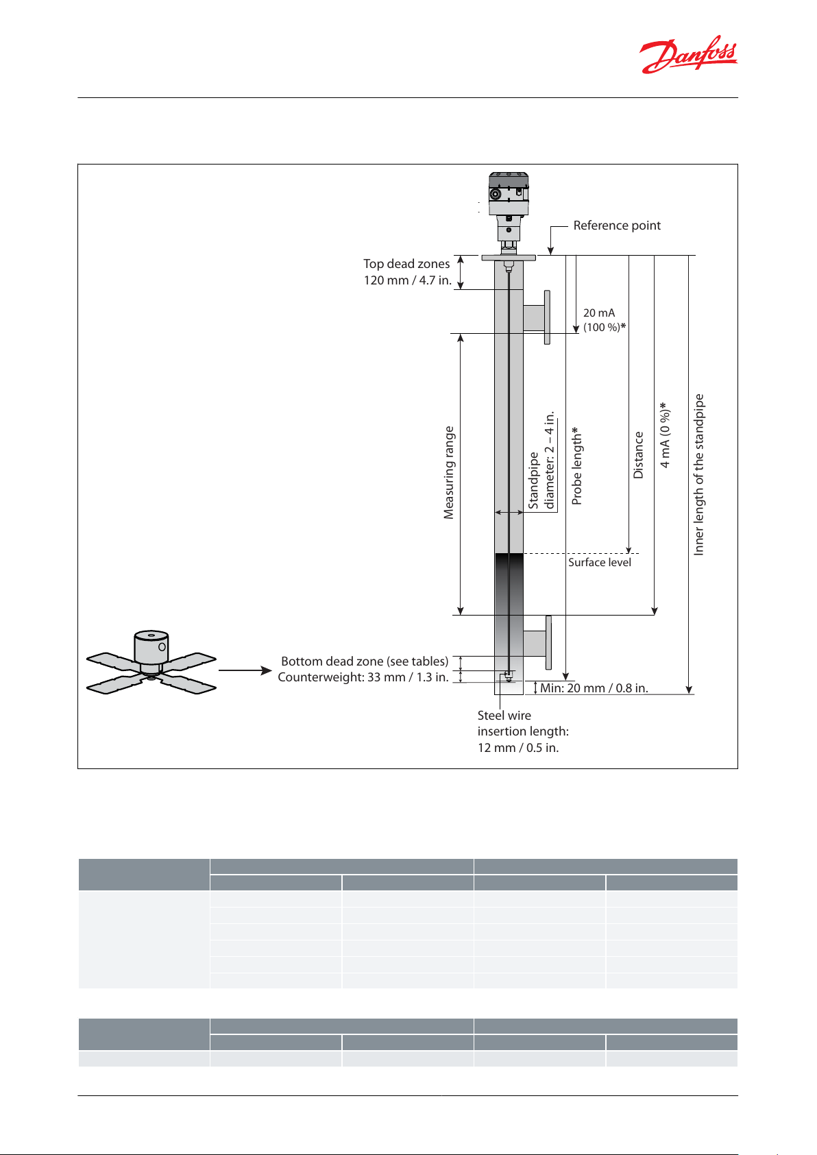
Top dead zones
120 mm / 4.7 in.
Measuring range
Bottom dead zone (see tables)
Counterweight: 33 mm / 1.3 in.
Min: 20 mm / 0.8 in.
Steel wire
insertion length:
12 mm / 0.5 in.
Probe length*
4 mA (0 %)*
Inner length of the standpipe
20 mA
(100 %)*
Reference point
Distance
Surface level
Standpipe
diameter: 2 – 4 in.
Refrigerant
Probe length range
Bottom dead zone
[mm]
[in.]
[mm]
[in.]
Ammonia, HFC, HCFC
800
31.5
115
4.2
801 – 999
31.5 – 39
120
4.7
1000 – 1999
39 – 79
150
5.9
2000 – 2999
79 – 118
180
7.1
3000 – 3999
118 – 157
210
8.3
4000 – 5000
157 – 197
240
9.4
Refrigerant
Probe length range
Bottom dead zone
[mm]
[in.]
[mm]
[in.]
Ammonia, HFC, HCFC
800 – 5000
31.5 – 197903.5
Liquid level sensor, type AKS 4100 and AKS 4100U
Measuring range of AKS 4100/4100U - CABLE version
Figure 9: Measuring range of AKS 4100/4100U - CABLE version
NOTE:
* Values to be entered into HMI Quick Setup menu and recorded on the setting label. Stick the setting label onto the
Signal Converter either inside or outside.
Table 13: Bottom deadzone values based on the factory setting of dielectric constant
Table 14: Improved Bottom dead zone values after the adjustment of dielectric constant
© Danfoss | Climate Solutions | 2021.07 AI243386442914en-001101 | 11

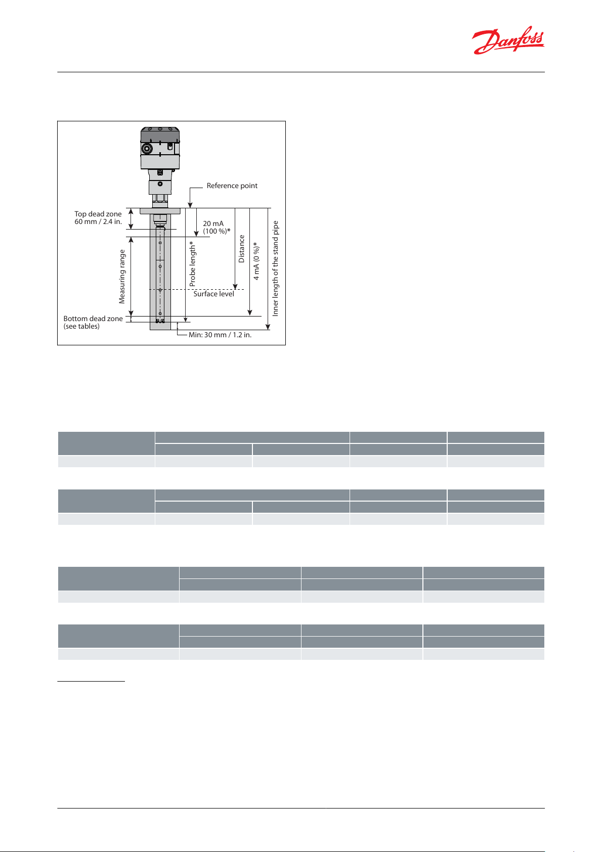
Top
dead
zone
120 mm /
4.7 in.
Measuring range
Bottom
dead
zone
(see tables)
Min: 30 mm / 1.2 in.
Probe length*
4 mA (0 %)*
Inner length of the stand pipe
20 mA
(100 %)*
Reference point
Distance
Surface level
Refrigerant
Probe length
Bottom Dead Zone
Bottom Dead Zone
[mm]
[in.]
[mm]
[in.]
CO
2
500
19.7
170
6.7
800
31.5
1000
39.4
1200
47.2
1500
59.1
1700
66.9
2200
86.6
Liquid level sensor, type AKS 4100 and AKS 4100U
Measuring range of AKS 4100/4100U - COAXIAL D14 version
Figure 10: Measuring range of AKS 4100/4100U - COAXIAL D14 version
NOTE:
* Values to be entered into HMI Quick Setup menu and recorded on the setting label. Stick the setting label onto the
Signal Converter either inside or outside.
AKS 4100
Table 15: Dielectric Constant εr always set during Quick Setup
© Danfoss | Climate Solutions | 2021.07 AI243386442914en-001101 | 12

Refrigerant
Probe length
Bottom Dead Zone
Bottom Dead Zone
[mm]
[in.]
[mm]
[in.]
Ammonia
500
19.7953.7
800
31.5
104
4.1
1000
39.4
110
4.3
1200
47.2
116
4.6
1500
59.1
125
4.9
1700
66.9
131
5.2
2200
86.6
146
5.8
Refrigerant
Probe length
Bottom Dead Zone
Bottom Dead Zone
[mm]
[in.]
[mm]
[in.]
Ammonia
500
19.7
80
3.2
800
31.5
1000
39.4
1200
47.2
1500
59.1
1700
66.9
2200
86.6
Refrigerant
Probe length
Bottom Dead Zone
Bottom Dead Zone
[mm]
[in.]
[mm]
[in.]
HCFC,HFC
500
19.7
115
4.5
800
31.5
124
4.9
1000
39.4
130
5.1
1200
47.2
136
5.4
1500
59.1
145
5.7
1700
66.9
151
5.9
2200
86.6
166
6.5
Refrigerant
Probe length
Bottom Dead Zone
Bottom Dead Zone
[mm]
[in.]
[mm]
[in.]
HCFC,HFC
500
19.7
100
3.9
800
31.5
1000
39.4
1200
47.2
1500
59.1
1700
66.9
2200
86.6
Refrigerant
Probe Length
Bottom Dead Zone
Bottom Dead Zone
[in.]
[in.]
[mm]
CO
2
19.2
6.7
170
3045556585
Liquid level sensor, type AKS 4100 and AKS 4100U
Table 16: Factory setting
Table 17: Improved Bottom dead zone values after the adjustment of dielectric constant
Table 18: Factory setting
Table 19: Improved Bottom dead zone values after the adjustment of dielectric constant
NOTE:
It is mandatory to input dielectric constant for CO2 applications.
AKS 4100U
Table 20: Dielectric Constant εr always set during Quick Setup
© Danfoss | Climate Solutions | 2021.07 AI243386442914en-001101 | 13

Refrigerant
Probe Length
Bottom Dead Zone
Bottom Dead Zone
[in.]
[in.]
[mm]
Ammonia
19.2
3.739530
4.05
103454.5
114554.8
122655.1
130855.7
145
Refrigerant
Probe Length
Bottom Dead Zone
Bottom Dead Zone
[in.]
[in.]
[mm]
Ammonia
19.2
3.1
80
3045556585
Refrigerant
Probe Length
Bottom Dead Zone
Bottom Dead Zone
[in.]
[in.]
[mm]
HCFC,HFC
19.2
4.52
115304.84
123455.29
134555.59
142655.89
150856.49
165
Refrigerant
Probe Length
Bottom Dead Zone
Bottom Dead Zone
[in.]
[in.]
[mm]
HCFC,HFC
19.2
3.94
100
3045556585
Liquid level sensor, type AKS 4100 and AKS 4100U
Table 21: Factory setting
Table 22: Improved Bottom dead zone values after the adjustment of dielectric constant
Table 23: Factory setting
Table 24: Improved Bottom dead zone values after the adjustment of dielectric constant
NOTE:
It is mandatory to input dielectric constant for CO2 applications.
© Danfoss | Climate Solutions | 2021.07 AI243386442914en-001101 | 14
Measuring range
4 mA (0 %)*
Top dead zone
60 mm / 2.4 in.
Bottom dead zone
(see tables)
20 mA
(100 %)*
Probe length*
Reference point
Distance
Surface level
Inner length of the stand pipe
Min: 30 mm / 1.2 in.
Refrigerant
Probe length
Bottom Dead Zone
Bottom Dead Zone
[mm]
[in.]
[mm]
[in.]
Ammonia
2801148
1.9
Refrigerant
Probe length
Bottom Dead Zone
Bottom Dead Zone
[mm]
[in.]
[mm]
[in.]
Ammonia
2801140
1.6
Refrigerant
Probe Length
Bottom Dead Zone
Bottom Dead Zone
[in.]
[in.]
[mm]
Ammonia
11
1.9
48
Refrigerant
Probe Length
Bottom Dead Zone
Bottom Dead Zone
[in.]
[in.]
[mm]
Ammonia
11
1.6
40
Liquid level sensor, type AKS 4100 and AKS 4100U
Measuring range of AKS 4100/4100U - COAXIAL D22 version
Figure 11: Measuring range of AKS 4100/4100U - COAXIAL D22 version
NOTE:
* Values to be entered into HMI Quick Setup menu and recorded on the setting label. Stick the setting label onto the
Signal Converter either inside or outside.
AKS 4100
Table 25: Factory setting
Table 26: Improved Bottom dead zone values after the adjustment of dielectric constant
AKS 4100U
Table 27: Factory setting
Table 28: Improved Bottom dead zone values after the adjustment of dielectric constant
Connections
Mechanical connection
Cable version / Coaxial version:
• AKS 4100
◦ G1 in. pipe thread
◦ Aluminium gasket included
• AKS 4100U
3
◦
⁄4 in. NPT
© Danfoss | Climate Solutions | 2021.07 AI243386442914en-001101 | 15
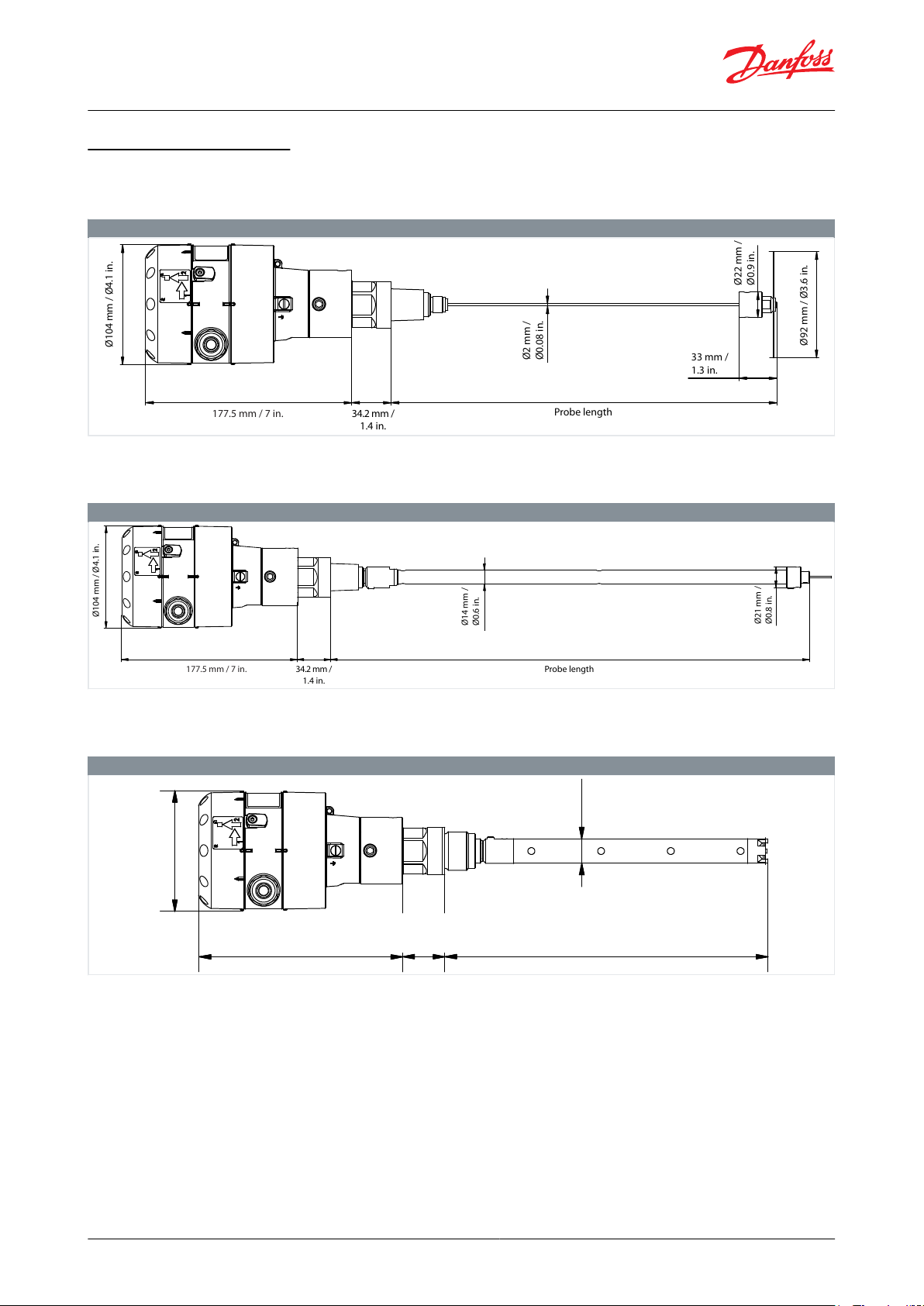
Weight: approx. 2.3 kg / 5.1 lbs
Probe length
Ø104 mm / Ø4.1 in.
177.5 mm / 7 in. 34.2 mm /
1.4 in.
Ø2 mm /
Ø0.08 in.
Ø22 mm /
Ø0.9 in.
Ø92 mm / Ø3.6 in.
33 mm /
1.3 in.
Weight: approx. 3.8 kg / 8.4 lbs
Ø104 mm / Ø4.1 in.
177.5 mm / 7 in. 34.2 mm /
1.4 in.
Probe length
Ø14 mm /
Ø0.6 in.
Ø21 mm /
Ø0.8 in.
Weight: 2.4 kg / 5.3 lbs
Ø 104 mm / Ø 4.1 in.
177.5 mm / 7 in.
34.2 mm /
1.4 in.
Probe length
21.1 mm /
0.8 in.
Liquid level sensor, type AKS 4100 and AKS 4100U
Dimensions and weights
CABLE version
Table 29: CABLE version
COAXIAL D14 version
Table 30: Coaxial D14 version
COAXIAL D22 version
Table 31: Coaxial D22 version
© Danfoss | Climate Solutions | 2021.07 AI243386442914en-001101 | 16
Description
Refrigerant
Code number with HMI
English (default)
German
French
Spanish
Code number with HMI
English (default)
Japanese
Chinese
Russian
Code number Without
HMI*
AKS 4100 with 5 m / 197 in., Ø2 mm / Ø0.08
in. stainless cable and counterweight
Ammonia, R134A, R404A, R410A, R22
084H4501
084H4550
084H4500
AKS 4100U with 5 m / 197 in., Ø2 mm / Ø0.08
in. stainless cable and counterweight
Ammonia, R134A, R404A, R410A, R22
084H4521
084H4571
084H4520
Description
Probe length
Refrigerant
Code number with
HMI
English (default)
German
French
Spanish
Code number with
HMI
English (default)
Japanese
Chinese
Russian
Code number With‐
out HMI*
mm
in.
AKS 4100 - Coaxial D14
500
Ammonia, CO
2
, R134A, R404A, R410A, R22
084H4510
084H4560
084H4503
AKS 4100 - Coaxial D14
800
Ammonia, CO
2
, R134A, R404A, R410A, R22
084H4511
084H4561
084H4504
AKS 4100 - Coaxial D14
1000
Ammonia, CO
2
, R134A, R404A, R410A, R22
084H4512
084H4562
084H4505
AKS 4100 - Coaxial D14
1200
Ammonia, CO
2
, R134A, R404A, R410A, R22
084H4513
084H4563
084H4506
AKS 4100 - Coaxial D14
1500
Ammonia, CO
2
, R134A, R404A, R410A, R22
084H4514
084H4564
084H4507
AKS 4100 - Coaxial D14
1700
Ammonia, CO
2
, R134A, R404A, R410A, R22
084H4515
084H4565
084H4508
AKS 4100 - Coaxial D14
2200
Ammonia, CO
2
, R134A, R404A, R410A, R22
084H4516
084H4566
084H4509
Liquid level sensor, type AKS 4100 and AKS 4100U
Ordering
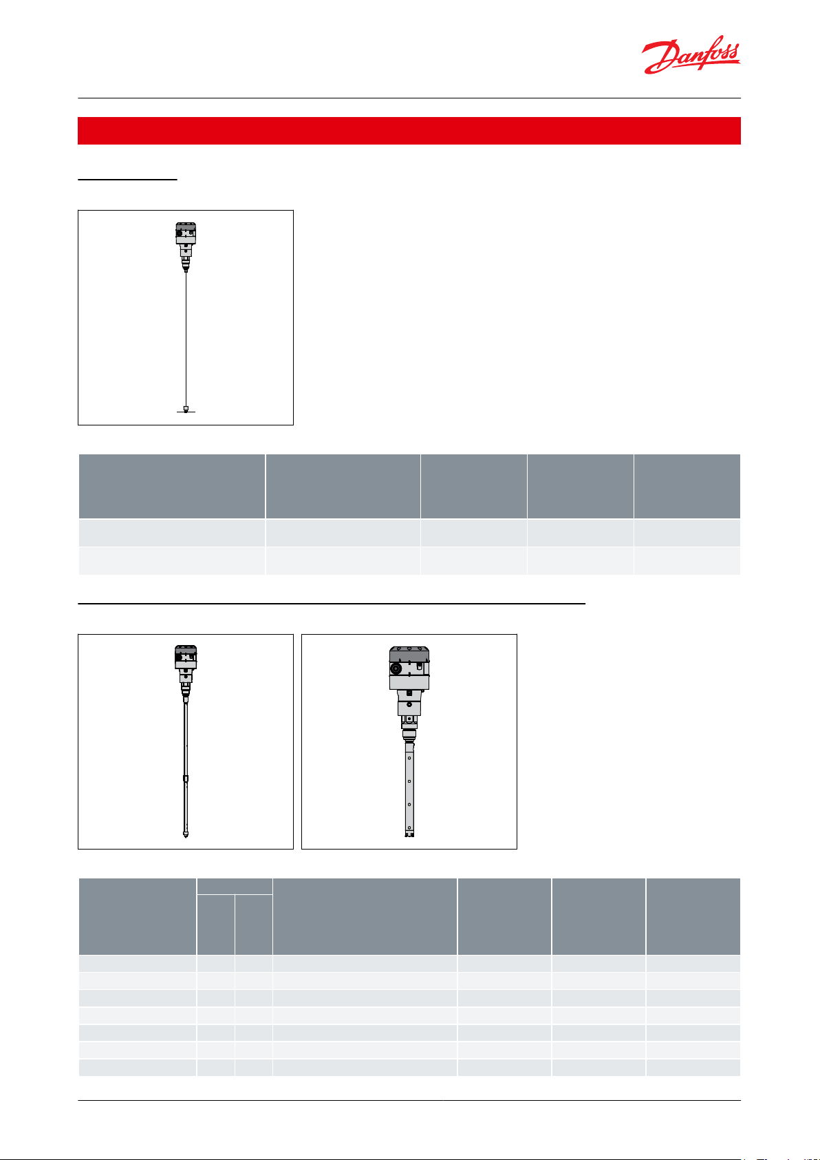
Cable version
Figure 12: Cable version
Table 32: Cable version
Coaxial version (available in predened lengths, with or without HMI)
Figure 13: Coaxial version D14 Figure 14: Coaxial version D22
Table 33: Coaxial version - D14
© Danfoss | Climate Solutions | 2021.07 AI243386442914en-001101 | 17
Description
Probe length
Refrigerant
Code number with
HMI
English (default)
German
French
Spanish
Code number with
HMI
English (default)
Japanese
Chinese
Russian
Code number With‐
out HMI*
mm
in.
AKS 4100U - Coaxial D14
19.2
Ammonia, CO2, R134A, R404A, R410A, R22
084H4530
084H4580
084H4524
AKS 4100U - Coaxial D14
30
Ammonia, CO2, R134A, R404A, R410A, R22
084H4531
084H4581
084H4525
AKS 4100U - Coaxial D14
45
Ammonia, CO2, R134A, R404A, R410A, R22
084H4532
084H4582
084H4526
AKS 4100U - Coaxial D14
55
Ammonia, CO2, R134A, R404A, R410A, R22
084H4533
084H4583
084H4527
AKS 4100U - Coaxial D14
65
Ammonia, CO2, R134A, R404A, R410A, R22
084H4534
084H4584
084H4528
AKS 4100U - Coaxial D14
85
Ammonia, CO2, R134A, R404A, R410A, R22
084H4535
084H4585
084H4529
Description
Probe length
Refrigerant
Code number with
HMI
English (default)
German
French
Spanish
Code number with
HMI
English (default)
Japanese
Chinese
Russian
Code number With‐
out HMI*
mm
in.
AKS 4100 - Coaxial D22
280
Ammonia
084H4517
084H4567
084H4518
AKS 4100U - Coaxial D22
11
Ammonia
084H4536
084H4586
084H4537
AKS 4100 - Coaxial D22
280
CO2, R134A, R404A, R410A, R22
084H4572
084H4573
084H4574
AKS 4100U - Coaxial D22
11
CO2, R134A, R404A, R410A, R22
084H4575
084H4576
084H4577
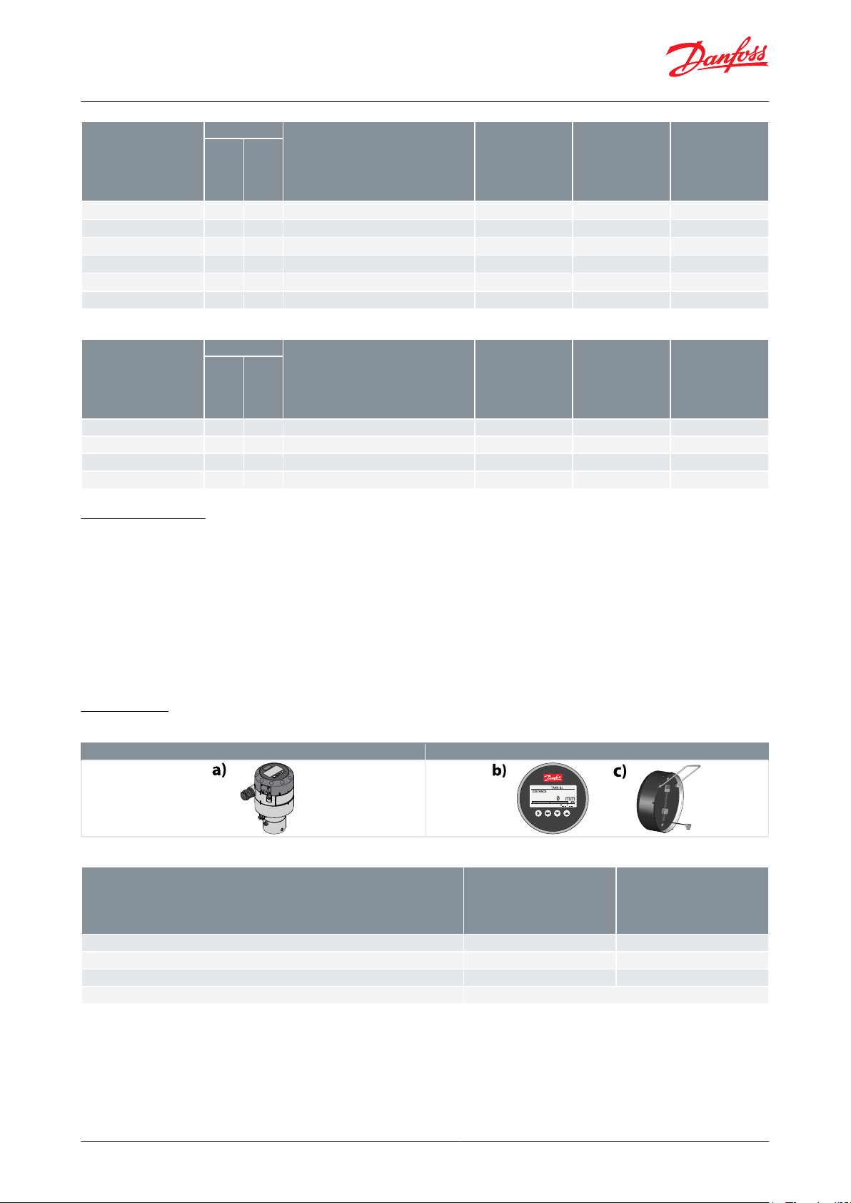
AKS 4100/4100U excluding cable gland
HMI Service/Display unit
Description
Code number with HMI
English (default)
German
French
Spanish
Code number with HMI
English (default)
Japanese
Chinese
Russian
AKS 4100/4100U HMI Service/Display unit with rear cover and mounting bracket -
c)
084H4540
084H4590
AKS 4100/4100U HMI Display -
b)
084H4548
084H4598
AKS 4100/4100U Signal Converter + Metaglass with HMI, excluding cable gland -
a)
084H4555
084H4556
AKS 4100/4100U converter connecting cable (5 pcs.)
084H4557
Liquid level sensor, type AKS 4100 and AKS 4100U
Table 34: Coaxial version - D22
HMI display unit
When ordering without HMI please observe:
NOTE: Each AKS 4100/AKS 4100 must always be programmed via the HMI display unit.
The HMI display unit can be ordered separately:
• 084H4540 / 084H4590 AKS 4100/4100U HMI display unit with rear cover and mounting bracket. The mounting
bracket is very useful when the AKS 4100/4100U have to be programmed. The same AKS 4100/4100U HMI display
unit can be used to programme more AKS 4100/4100U and both Cable and Coaxial versions.
• 084H4548 / 084H4598 AKS 4100/4100U HMI display unit (usually spare part).
Accessories
Table 35: Accessories
Table 36: Accessories
© Danfoss | Climate Solutions | 2021.07 AI243386442914en-001101 | 18
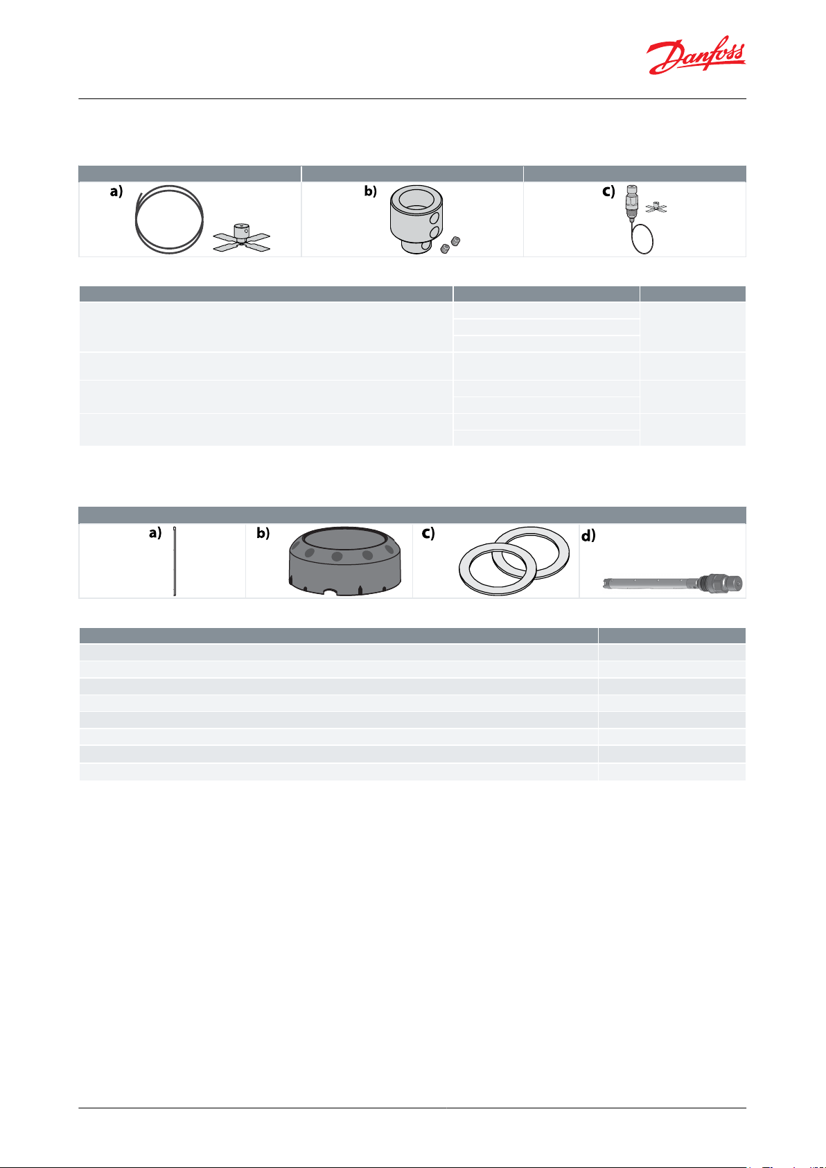
Cable and counterweight - CABLE version
End connector incl screws - COAXIAL D14 version
Process connection, counterweight and cable
Description
Content
Code number
Cable and counterweight for AKS 4100/4100U - CABLE version - a)
Cable - 5 m / 197 in., Ø2 mm / Ø0.08 in.
084H4542
Crimp
Counterweight
End connector incl screws for AKS 4100/4100U - COAXIAL D14 version - b)
End connector (incl. 3 mm / 0.12 in. set
screws)
084H4549
Process connection, counterweight and 5 m / 197 in., Ø2 mm / Ø0.08 in. cable for AKS 4100
- CABLE and COAXIAL D14 version - c)
1 in. process connection
084H4545
Counterweight
Process connection, counterweight and 5 m / 197 in., Ø2 mm / Ø0.08 in. cable for AKS
4100U - CABLE and COAXIAL D14 version - c)
3
⁄4 in. NPT process connection
084H4546
Counterweight
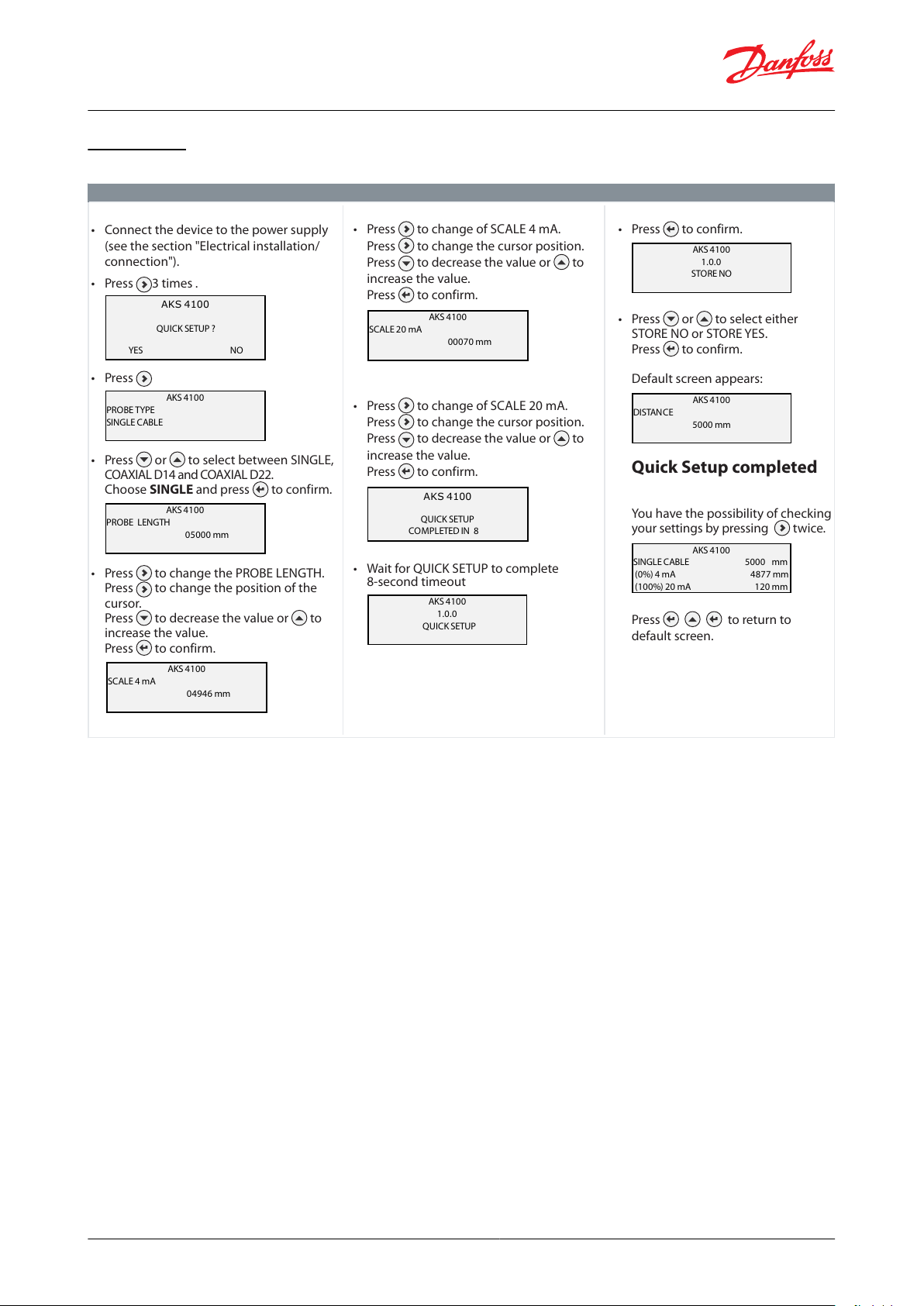
Other spare parts
Description
Code number
AKS 4100/4100U Coaxial tube. Tube length: 680 mm / 26.8 in. - a)
084H4543
AKS 4100/4100U blank top cover for signal converter - b)
084H4544
AKS 4100/4100U Aluminium gaskets (10 pcs.) for 1 in. process connection - c)
084H4547
AKS 4100 1 in. welding connection
027F1010
Process connection AKS 4100 - Coaxial D22 - G1 in. - 280 mm. For Ammonia only - d)
084H4551
Process connection AKS 4100U - Coaxial D22 -
3
⁄4 in. NPT – 11 in. For Ammonia only - d)
084H4552
Process connection AKS 4100 - Coaxial D22 - G1 in. - 280 mm. For CO2, R134A, R404A, R410A, R22 only - d)
084H4558
Process connection AKS 4100 - Coaxial D22 -
3
⁄4 in. NPT – 11 in. For CO
2
, R134A, R404A, R410A, R22 only - d)
084H4559
Liquid level sensor, type AKS 4100 and AKS 4100U
Service kits
Table 37: Service kits
Table 38: Service kits
Other spare parts
Table 39: Other spare parts
Table 40: Other spare parts
© Danfoss | Climate Solutions | 2021.07 AI243386442914en-001101 | 19
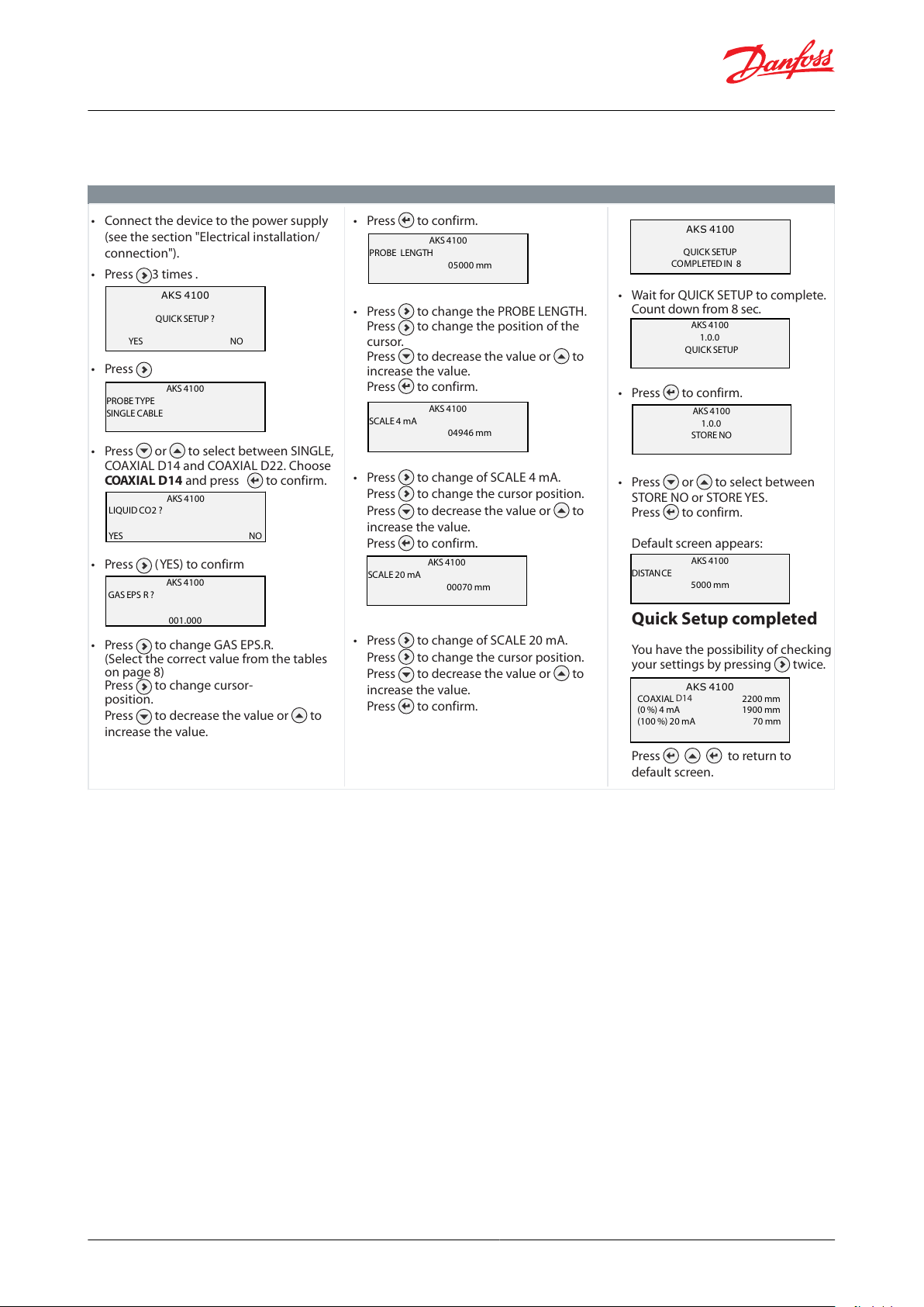
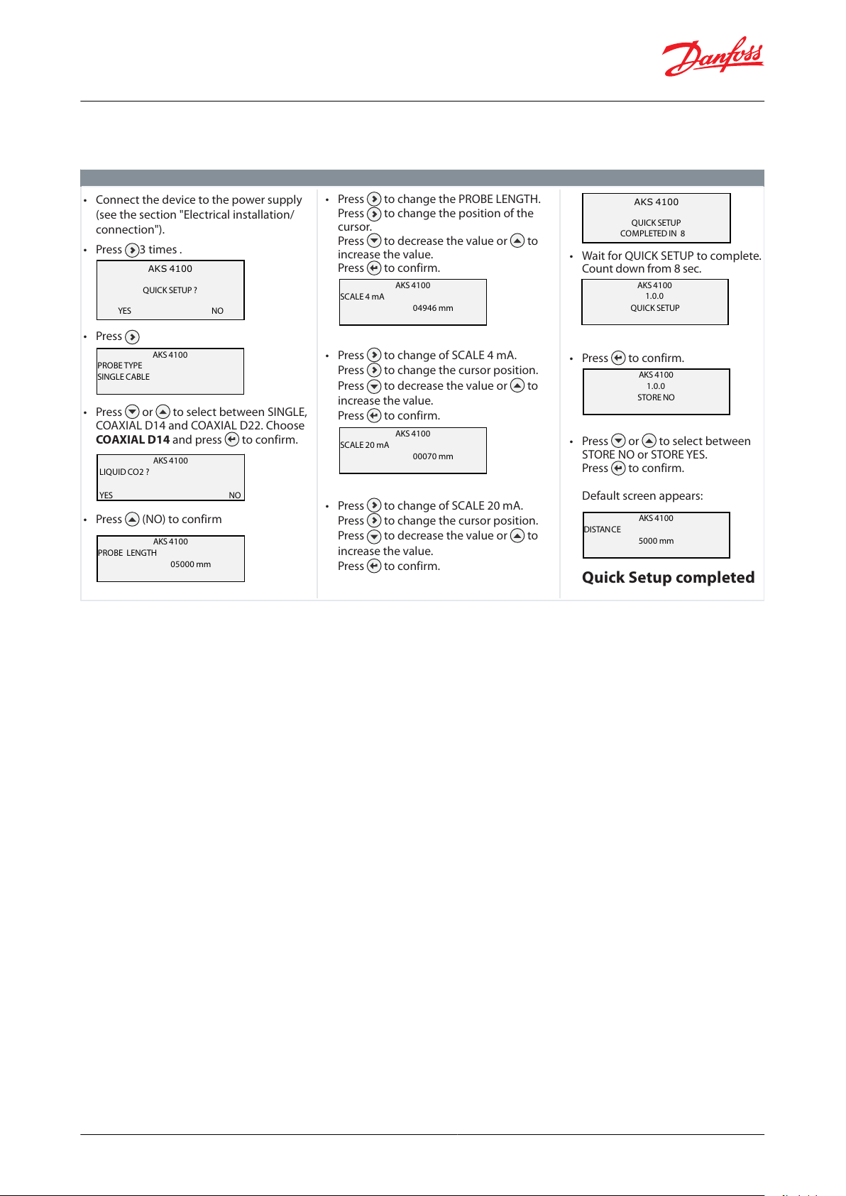
Quick Setup (all values below are only examples)
• Connect the device to the power supply
(see the section "Electrical installation/
connection").
• Press 3 times .
• Press
• Press or to select between SINGLE,
COAXIAL D14 and COAXIAL D22.
Choose SINGLE and press to confirm.
• Press to change the PROBE LENGTH.
Press to change the position of the
cursor.
Press to decrease the value or to
increase the value.
Press to confirm.
AKS 4100
QUICK SETUP?
YES NO
AKS 4100
PROBE TYPE
SINGLE CABLE
AKS 4100
PROBE LENGTH
05000 mm
AKS 4100
SCALE 4mA
04946 mm
AKS 4100
SCALE 20 mA
00070 mm
• Press to change of SCALE 4 mA.
Press to change the cursor position.
Press to decrease the value or to
increase the value.
Press to confirm.
• Press to change of SCALE 20 mA.
Press to change the cursor position.
Press to decrease the value or to
increase the value.
Press to confirm.
• Wait for QUICK SETUP to complete
8-second timeout
AKS 4100
QUICK SETUP
COMPLETED IN 8
AKS 4100
1.0.0
QUICK START
AKS 4100
1.0.0
STORE NO
AKS 4100
DISTANCE
5000 mm
• Press to confirm.
• Press or to select either
STORE NO or STOREYES.
Press to confirm.
Default screen appears:
Quick Setup completed
You have the possibility of checking
your settings by pressing twice.
Press to return to
default screen.
QUICK SETUP?
QUICK SETUP
AKS 4100
SINGLE CABLE 5000 mm
(0%) 4 mA 4877 mm
(100%) 20 mA 120 mm
Liquid level sensor, type AKS 4100 and AKS 4100U
Quick setup
Table 41: Quick Setup
NOTE:
The signal converter can be programmed with or without mechanical process connector assembled.
© Danfoss | Climate Solutions | 2021.07 AI243386442914en-001101 | 20
Quick Setup (all values below are only examples)
• Connect the device to the power supply
(see the section "Electrical installation/
connection").
• Press 3 times .
• Press
• Press or to select between SINGLE,
COAXIAL D14 and COAXIAL D22. Choose
COAXIAL D14 and press to confirm.
• Press (YES) to confirm
• Press to change GAS EPS.R.
(Select the correct value from the tables
on page 8)
Press to change cursor-
position.
Press to decrease the value or to
increase the value.
AKS 4100
QUICK SETUP?
YES NO
AKS 4100
PROBE TYPE
SINGLE CABLE
• Press to confirm.
• Press to change the PROBE LENGTH.
Press to change the position of the
cursor.
Press to decrease the value or to
increase the value.
Press to confirm.
• Press to change of SCALE 4 mA.
Press to change the cursor position.
Press to decrease the value or to
increase the value.
Press to confirm.
• Press to change of SCALE 20 mA.
Press to change the cursor position.
Press to decrease the value or to
increase the value.
Press to confirm.
• Wait for QUICK SETUP to complete.
Count down from 8 sec.
• Press to confirm.
• Press or to select between
STORE NO or STOREYES.
Press to confirm.
Default screen appears:
Quick Setup completed
You have the possibility of checking
your settings by pressing twice.
Press to return to
default screen.
AKS 4100
GAS EPS R ?
001.000
AKS 4100
PROBE LENGTH
05000 mm
AKS 4100
SCALE 4mA
04946 mm
AKS 4100
SCALE 20 mA
00070 mm
AKS 4100
QUICK SETUP
COMPLETED IN 8
AKS 4100
1.0.0
QUICK START
AKS 4100
1.0.0
STORE NO
AKS 4100
DISTANCE
5000 mm
AKS 4100
LIQUID CO2 ?
YES NO
QUICK SETUP
AKS 4100
COAXIAL 220 0mm
(0 %) 4 mA 1900 mm
(100 %) 20 mA 70 mm
D14
Liquid level sensor, type AKS 4100 and AKS 4100U
When CO2 is used:
Table 42: Quick Setup (all values below are only examples)
NOTE:
The signal converter can be programmed with or without mechanical process connector assembled.
© Danfoss | Climate Solutions | 2021.07 AI243386442914en-001101 | 21
For all other refrigerants
• Connect the device to the power supply
(see the section "Electrical installation/
connection").
• Press 3 times .
• Press
• Press or to select between SINGLE,
COAXIAL D14 and COAXIAL D22. Choose
COAXIAL D14 and press to confirm.
• Press (NO) to confirm
AKS 4100
QUICK SETUP?
YES NO
AKS 4100
PROBE TYPE
SINGLE CABLE
• Press to change the PROBE LENGTH.
Press to change the position of the
cursor.
Press to decrease the value or to
increase the value.
Press to confirm.
• Press to change of SCALE 4 mA.
Press to change the cursor position.
Press to decrease the value or to
increase the value.
Press to confirm.
• Press to change of SCALE 20 mA.
Press to change the cursor position.
Press to decrease the value or to
increase the value.
Press to confirm.
• Wait for QUICK SETUP to complete.
Count down from 8 sec.
• Press to confirm.
• Press or to select between
STORE NO or STOREYES.
Press to confirm.
Default screen appears:
Quick Setup completed
AKS 4100
LIQUID CO2 ?
YES NO
AKS 4100
SCALE 4mA
04946 mm
AKS 4100
SCALE 20 mA
00070 mm
AKS 4100
QUICK SETUP
COMPLETED IN 8
AKS 4100
1.0.0
STORE NO
AKS 4100
DISTANCE
5000 mm
AKS 4100
1.0.0
QUICK START
AKS 4100
PROBE LENGTH
05000 mm
QUICK SETUP
Liquid level sensor, type AKS 4100 and AKS 4100U
For all other refrigerants
Table 43: For all other refrigerants
NOTE:
Please note that Coaxial D22 version can only be used in R717/NH3)
© Danfoss | Climate Solutions | 2021.07 AI243386442914en-001101 | 22
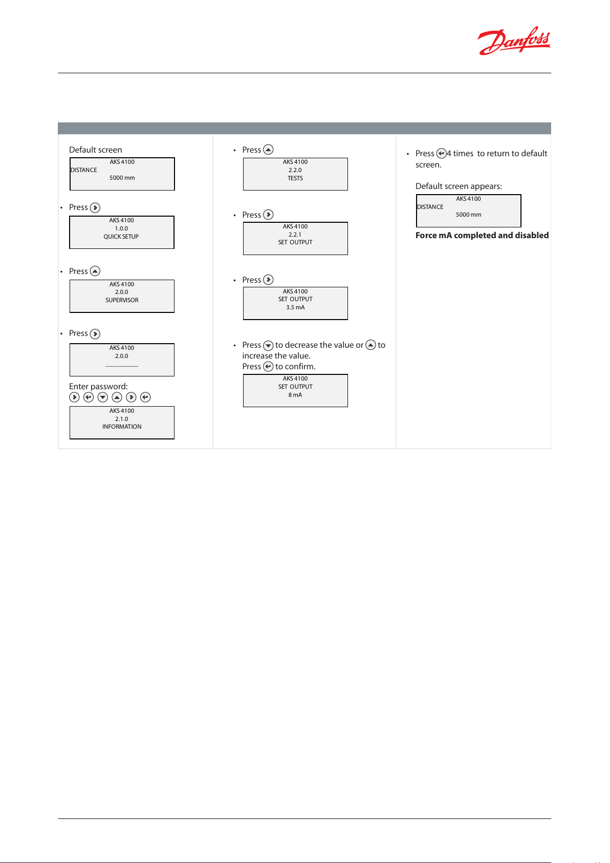
Forcing mA output (all values below are only examples)
Default screen
• Press
• Press
• Press
Enter password:
AKS 4100
DISTANCE
5000 mm
AKS 4100
2.0.0
SUPERVISOR
AKS 4100
2.0.0
____ ______
AKS 4100
2.1.0
INFORMATION
AKS 4100
2.2.0
TESTS
AKS 4100
2.2.1
SET O UTPUT
AKS 4100
SET O UTPUT
3.5 mA
AKS 4100
SET O UTPUT
8 mA
AKS 4100
DISTANCE
5000 mm
• Press
• Press
• Press
• Press to decrease the value or to
increase the value.
Press to confirm.
• Press 4 times to return to default
screen.
Default screen appears:
Force mA completed and disabled
AKS 4100
1.0.0
QUICK START
QUICK SETUP
Liquid level sensor, type AKS 4100 and AKS 4100U
CABLE and COAXIAL version
Table 44: CABLE and COAXIAL version
Entering refrigerant dielectric gas constant
Optional Procedure
Optional Procedure If the temperature condition in the stand pipe is known, a constant (dielectric constant of the
refrigerant gas) can be entered (parameter 2.5.3 GAS EPS.R), in order to obtain lower Top and Bottom Dead Zone
values (see Measuring range of AKS 4100/4100U - CABLE version and Measuring range of AKS 4100/4100U -
COAXIAL D14 version ).
© Danfoss | Climate Solutions | 2021.07 AI243386442914en-001101 | 23
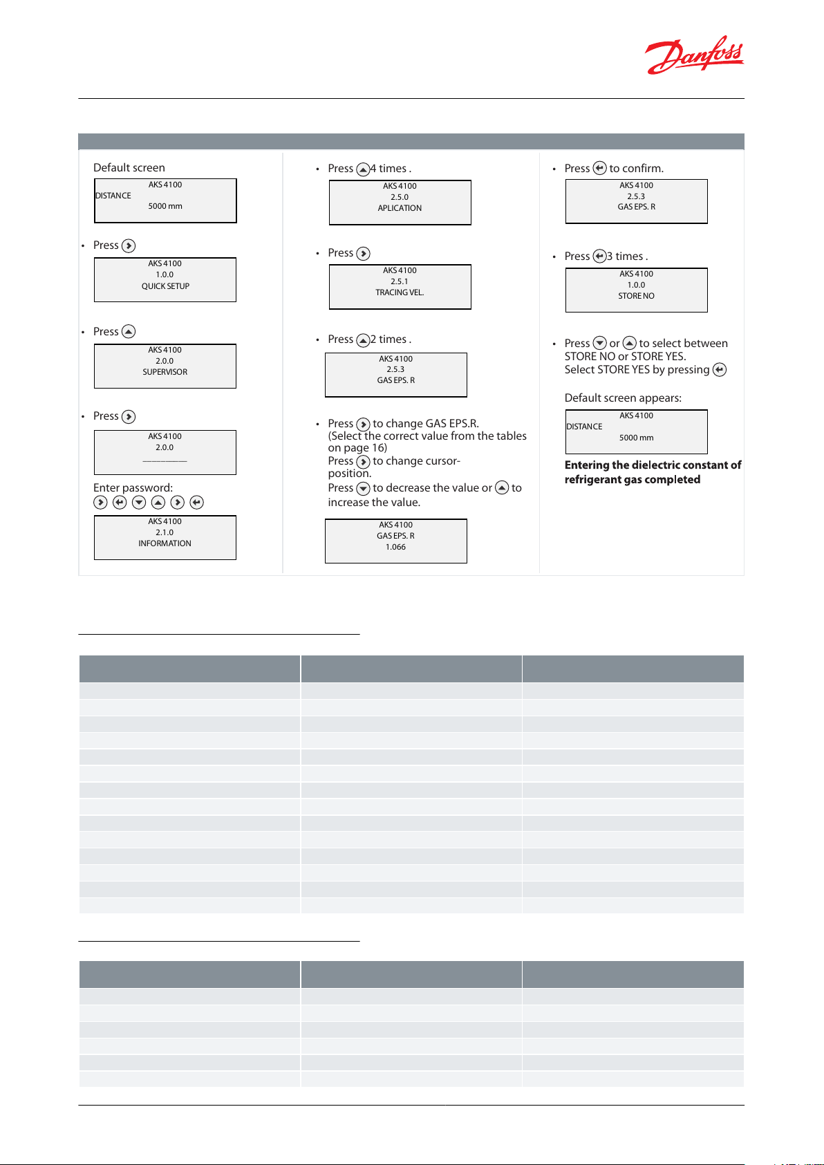
Entering refrigerant dielectric gas constant (all values below are only examples)
Default screen
• Press
• Press
• Press
Enter password:
AKS 4100
DISTANCE
5000 mm
AKS 4100
1.0.0
QUICK START
AKS 4100
2.0.0
SUPERVISOR
AKS 4100
2.0.0
____ ______
AKS 4100
2.1.0
INFORMATION
AKS 4100
2.5.0
APLICATION
AKS 4100
2.5.1
TRACING VEL.
• Press 4 times .
• Press
• Press 2 times .
• Press to change GAS EPS.R.
(Select the correct value from the tables
on page 16)
Press to change cursor-
position.
Press to decrease the value or to
increase the value.
AKS 4100
2.5.3
GAS EPS. R
AKS 4100
GAS EPS. R
1.066
AKS 4100
2.5.3
GAS EPS. R
AKS 4100
1.0.0
STORE NO
AKS 4100
DISTANCE
5000 mm
• Press to confirm.
• Press 3 times .
• Press or to select between
ST
Select STORE YES by pressing
ORE NO or STORE YES.
Default screen appears:
QUICK SETUP
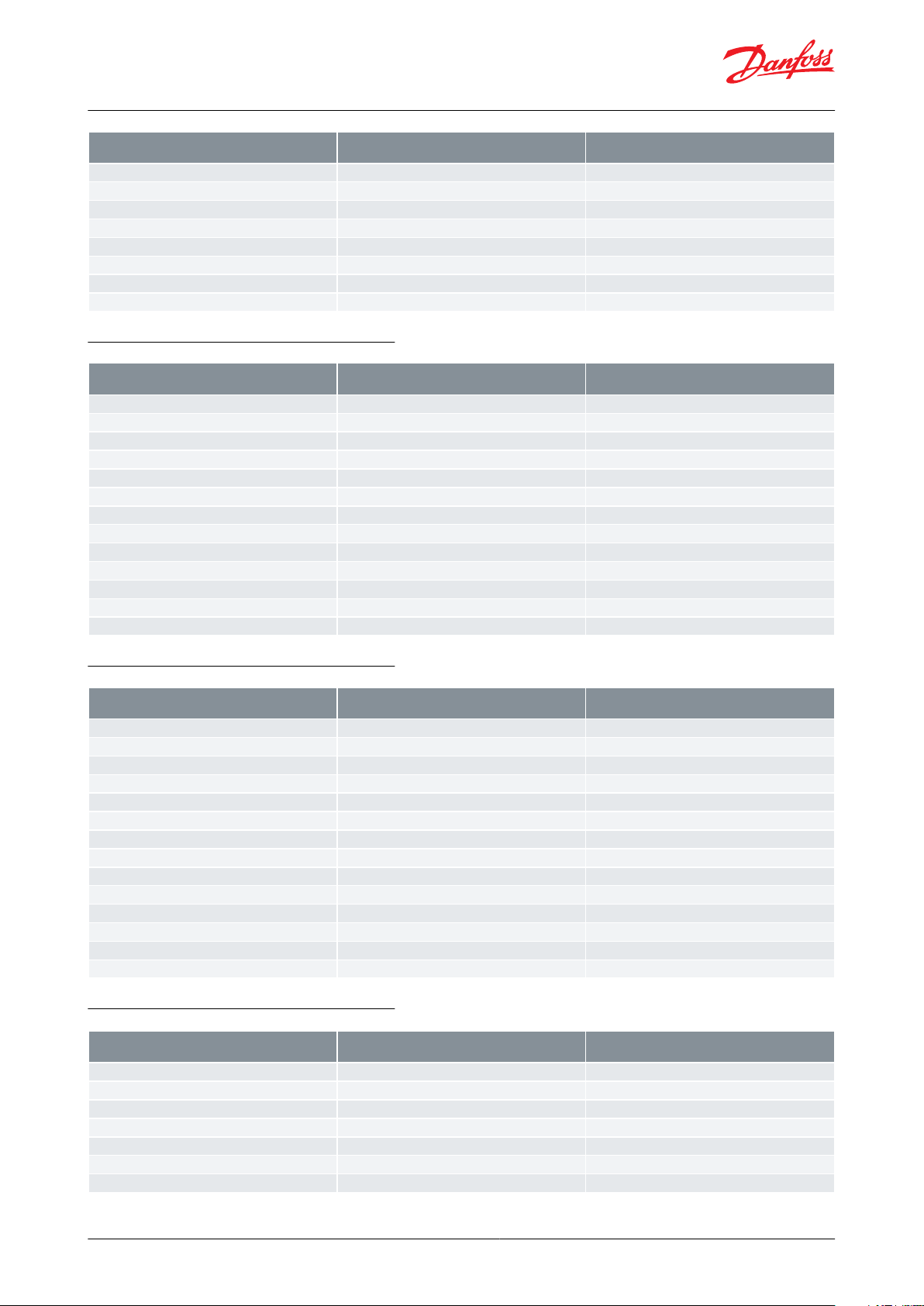
Temperature [°C]
Temperature [°F]
Dielectric constant of refrigerant gas Parameter
2.5.3 GAS EPS.R
-60 – -42
-76 – -43
1
-41 – -18
42 – 0
1.01
-17 – -5
1 – 23
1.02
-4 – 4
24 – 39
1.03
5 – 12
40 – 54
1.04
13 – 18
55 – 64
1.05
19 – 24
65 – 75
1.06
25 – 28
76 – 82
1.07
29 – 33
83 – 91
1.08
34 – 37
92 – 99
1.09
38 – 40
100 – 104
1.1
41 – 44
105 – 111
1.11
45 – 47
112 – 117
1.12
48 – 50
118 – 122
1.13
Temperature [°C]
Temperature [°F]
Dielectric constant of refrigerant gas Parameter
2.5.3 GAS EPS.R
-60 – -50
-76 – -58
1
-49 – -25
57 – -13
1.01
-24 – -10
-12 – 14
1.02
-9 – 0
15 – 32
1.03
1 – 8
33 – 46
1.04
9 – 15
47 – 59
1.05
Liquid level sensor, type AKS 4100 and AKS 4100U
Table 45: Entering refrigerant dielectric gas constant
Saturated vapour dielectric constant (default value: 1.066)
Temperature range: -60 / +50 °C (-76 / +122 °F)
Table 46: R717 (NH3)
Temperature range: -60 / +48 °C (-76 / +118 °F)
Table 47: R22
© Danfoss | Climate Solutions | 2021.07 AI243386442914en-001101 | 24
Temperature [°C]
Temperature [°F]
Dielectric constant of refrigerant gas Parameter
2.5.3 GAS EPS.R
16 – 21
60 – 70
1.06
22 – 26
71 – 79
1.07
27 – 31
80 – 88
1.08
32 – 35
89 – 95
1.09
36 – 39
96 – 102
1.1
40 – 42
103 – 108
1.11
43 – 45
109 – 113
1.12
46 – 48
114 – 118
1.13
Temperature [°C]
Temperature [°F]
Dielectric constant of refrigerant gas Parameter
2.5.3 GAS EPS.R
-65 – -47
-85 – -52
1.01
-46 – -35
-51 – -31
1.02
-34 – -26
-30 – -14
1.03
-25 – -19
-13 – -2
1.04
-18 – -13
-1 – 9
1.05
-12 – -8
10 – 18
1.06
-7 – -4
19 – 25
1.07
-3 – 0
26 – 32
1.08
1 – 4
33 – 40
1.09
5 – 7
41 – 45
1.1
8 – 10
46 – 50
1.11
11 – 12
51 – 54
1.12
13 – 15
55 – 59
1.13
Temperature [°C]
Temperature [°F]
Dielectric constant of refrigerant gas Parameter
2.5.3 GAS EPS.R
-60 – -48
-76 – -54
1.01
-47 – -36
-53 – -32
1.02
-35 – -28
-31 – -18
1.03
-27 – -21
-17 – -6
1.04
-20 – -15
-17 – -5
1.05
-14 – -10
-4 – 14
1.06
-9 – -6
13 – 22
1.07
-5 – -2
23 – 29
1.08
-1 – 2
30 – 36
1.09
3 – 5
37 – 41
1.1
6 – 8
42 – 47
1.11
9 – 11
48 – 52
1.12
12 – 13
53 – 56
1.13
14 – 15
57 – 59
1.14
Temperature [°C]
Temperature [°F]
Dielectric constant of refrigerant gas Parameter
2.5.3 GAS EPS.R
-56.0 – -42.0
-69 – -43
1.01
-41.0 – -28.0
-42 – -18
1.02
-27.0 – -17.0
-17 – 2
1.03
-16.0 – -9.0
3 – 16
1.04
-8.0 – -3.0
17 – 27
1.05
-2.0 – 2
28 – 36
1.06
3 – 7
37 – 45
1.07
Liquid level sensor, type AKS 4100 and AKS 4100U
Temperature range: -65 / +15 °C (-85 / +59 °F)
Table 48: R410A
Temperature range: -60 / +15 °C (-76 / +59 °F)
Table 49: R507
Temperature range: -56 / +15 °C (-69 / +59 °F)
Table 50: R744 (CO2)
© Danfoss | Climate Solutions | 2021.07 AI243386442914en-001101 | 25

Temperature [°C]
Temperature [°F]
Dielectric constant of refrigerant gas Parameter
2.5.3 GAS EPS.R
8 – 11
46 – 52
1.08
12 – 14
53 – 58
1.091559
1.1
Temperature [°C]
Temperature [°F]
Dielectric constant of refrigerant gas Parameter
2.5.3 GAS EPS.R
-60 – -42
-76 – -43
1
-41 – -18
-42 – -0
1.01
-17 – -4
1 – 25
1.02
-3 – 5
26 – 41
1.03
6 – 13
42 – 56
1.04
14 – 20
57 – 68
1.05
21 – 25
69 – 77
1.06
26 – 30
78 – 86
1.07
31 – 34
87 – 94
1.08
35 – 38
95 – 100
1.09
39 – 42
101 – 108
1.1
43 – 45
109 – 113
1.11
46 – 48
114 – 119
1.12
49 – 50
120 – 122
1.13
Temperature [°C]
Temperature [°F]
Dielectric constant of refrigerant gas Parameter
2.5.3 GAS EPS.R
-60 – -47
-76 – -52
1.01
-46 – -35
-51 – -31
1.02
-34 – -26
-30 – -14
1.03
-25 – -19
-13 – -2
1.04
-18 – -14
-1 – 7
1.05
-13 – -9
8 – 16
1.06
-8 – -4
17 – 25
1.07
-3 – 0
26 – 32
1.08
1 – 3
33 – 38
1.09
4 – 6
39 – 43
1.1
7 – 9
44 – 49
1.11
10 – 12
50 – 54
1.12
13 – 15
55 – 59
1.13
Liquid level sensor, type AKS 4100 and AKS 4100U
Temperature range: -60 / +50 °C (-76 / + 122 °F)
Table 51: R134a
Temperature range: -60 / +15 °C (-76 / +59 °F)
Table 52: R404A
© Danfoss | Climate Solutions | 2021.07 AI243386442914en-001101 | 26
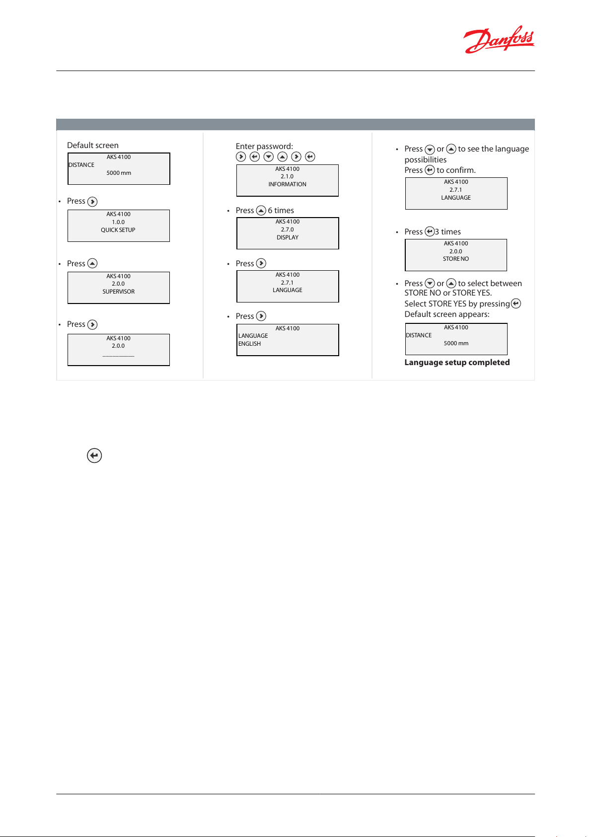
How to change the language setting (Default: English)
Default screen
• Press
• Press
• Press
AKS 4100
DISTANCE
5000 mm
AKS 4100
1.0.0
QUICK START
AKS 4100
2.0.0
SUPERVISOR
AKS 4100
2.0.0
____ ______
AKS 4100
2.1.0
INFORMATION
AKS 4100
DISTANCE
5000 mm
Enter password:
• Press 6 times
• Press
• Press
• Press or to see the language
possibilities
Press to confirm.
• Press 3 times
• Press or to select between
STORE NO or STOREYES.
Select STORE YES by pressing
Default screen appears:
Language setup completed
QUICK SETUP
AKS 4100
2.7.0
DISPLAY
AKS 4100
2.7.1
LANGUAGE
AKS 4100
LANGUAGE
ENGLISH
AKS 4100
2.7.1
LANGUAGE
AKS 4100
2.0.0
STORE NO
Liquid level sensor, type AKS 4100 and AKS 4100U
How to change the language setting (Default: English)
Table 53: How to change the language setting
Reset to factory setting
• Go to SUPERVISOR menu (see CABLE and COAXIAL version)
• Go to parameter 2.9.4 Reset Factory
• Select RESET FACTORY YES
• Press 3 times to return to default screen
• Factory reset completed
© Danfoss | Climate Solutions | 2021.07 AI243386442914en-001101 | 27

File name
Document type
Document topic
Approval authority
GOST FR.C.29.004.A 51938
Measuring - Performance Certicate
UA.1O146.D.00075-19
UA Declaration
EMCD/LVD
LLC CDC EURO-TYSK
033F0689.AA
EU Declaration
EMC
Danfoss
MD 033F0686.AH
Manufacturers Declaration
PED
Danfoss
033F0695.AA
Manufacturers Declaration
China RoHS
Danfoss
0F18749.513467890YTN
Pressure - Safety Certicate
CRN
TSSA
0F19272.2
Pressure - Safety Certicate
CRN
TSSA
This device fulls the statutory requirements of the EMC directives. The manufacturer certies successful testing of the product by applying the CE mark.
Valid for AKS 4100 - Not valid for AKS 4100U:
Pattern Approval Certicate of Measuring Instruments for the Russian Federation
Valid for AKS 4100 - Not valid for AKS 4100U:
In compliance with EMC regulations in the Russian Federation
EMC
EMC Directives 2004 / 108 / EC and 93 / 68 / EEC in conjunction with
EN 61326-1 (2006) and EN 61326-2-3 (2006). The device conforms to these standards if:
- the device has a coaxial probe or
- the device has a single probe that is installed in a metallic tank
LVD
Low-Voltage Directives 2006 / 95 / EC and 93 / 68 / EEC in conjunction with EN 61010-1 (2001)
NAMUR
NAMUR NE 21 Electromagnetic Compatibility (EMC) of Industrial Process and Laboratory Control Equipment
NAMUR NE 43 Standardization of the Signal Level for the Failure Information of Digital Transmitters
Liquid level sensor, type AKS 4100 and AKS 4100U
Certicates, declarations, and approvals
The list contains all certicates, declarations, and approvals for this product type. Individual code number may have
some or all of these approvals, and certain local approvals may not appear on the list.
Some approvals may change over time. You can check the most current status at danfoss.com or contact your local
Danfoss representative if you have any questions.
Table 54: Valid approvals
Table 55: Approvals and certication
© Danfoss | Climate Solutions | 2021.07 AI243386442914en-001101 | 28

Online support
Danfoss oers a wide range of support along with our products, including digital product information, software,
mobile apps, and expert guidance. See the possibilities below.
The Danfoss Product Store
The Danfoss Product Store is your one-stop shop for everything product related—no matter where
you are in the world or what area of the cooling industry you work in. Get quick access to essential
information like product specs, code numbers, technical documentation, certications, accessories,
and more.
Start browsing at store.danfoss.com.
Find technical documentation
Find the technical documentation you need to get your project up and running. Get direct access to
our ocial collection of data sheets, certicates and declarations, manuals and guides, 3D models
and drawings, case stories, brochures, and much more.
Start searching now at www.danfoss.com/en/service-and-support/documentation.
Danfoss Learning
Danfoss Learning is a free online learning platform. It features courses and materials specically
designed to help engineers, installers, service technicians, and wholesalers better understand the
products, applications, industry topics, and trends that will help you do your job better.
Create your Danfoss Learning account for free at www.danfoss.com/en/service-and-support/learning.
Get local information and support
Local Danfoss websites are the main sources for help and information about our company and
products. Find product availability, get the latest regional news, or connect with a nearby expert—all
in your own language.
Find your local Danfoss website here: www.danfoss.com/en/choose-region.
Spare Parts
Get access to the Danfoss spare parts and service kit catalog right from your smartphone. The app
contains a wide range of components for air conditioning and refrigeration applications, such as
valves, strainers, pressure switches, and sensors.
Download the Spare Parts app for free at www.danfoss.com/en/service-and-support/downloads.
Coolselector®2 - nd the best components for you HVAC/R system
Coolselector®2 makes it easy for engineers, consultants, and designers to nd and order the best
components for refrigeration and air conditioning systems. Run calculations based on your operating
conditions and then choose the best setup for your system design.
Download Coolselector®2 for free at coolselector.danfoss.com.
Any information, including, but not limited to information on selection of product, its application or use, product design, weight, dimensions, capacity or any other
technical data in product manuals, catalogues descriptions, advertisements, etc. and whether made available in writing, orally, electronically, online or via download,
shall be considered informative, and is only binding if and to the extent, explicit reference is made in a quotation or order conrmation. Danfoss cannot accept any
responsibility for possible errors in catalogues, brochures, videos and other material. Danfoss reserves the right to alter its products without notice. This also applies to
products ordered but not delivered provided that such alterations can be made without changes to form, t or function of the product. All trademarks in this material
are property of Danfoss A/S or Danfoss group companies. Danfoss and the Danfoss logo are trademarks of Danfoss A/S. All rights reserved.
© Danfoss | Climate Solutions | 2021.07 AI243386442914en-001101 | 29
 Loading...