

1
205 mm
[8 in]
140 mm
[5 1/2 in]
220 mm
[8 5/8 in]
88 mm
[3 1/2 in]
50 mm
[2 in]
29 mm
[1 1/8 in]
2
Installation guide
AKS 38
LLS 4000 retrofit
148R9529
1
2
1
220 mm
[8 5/8 in]
2
140 mm
[5 1/2 in]
148R9529
[8 in]
205 mm
88 mm
[3 1/2 in]
[2 in]
50 mm
29 mm
[1 1/8 in]
3
24 V DC
1
24 V DC
Black
White
Green
Red
4
* Danfoss code number 080Z0053, AK-PS 075, or similar
© Danfoss | DCS (ms) | 2021.04 AN375739676136en -000101 | 1
45°
ENGLISH
Refrigerants
Applicable to:
Ammonia R717
HCFC R22, R507A
HFC
R407A, R404A, R410A, R134A, R513A
Temperature range
-50 °C/+65 °C (-58 °F/149 °F)
Pressure range
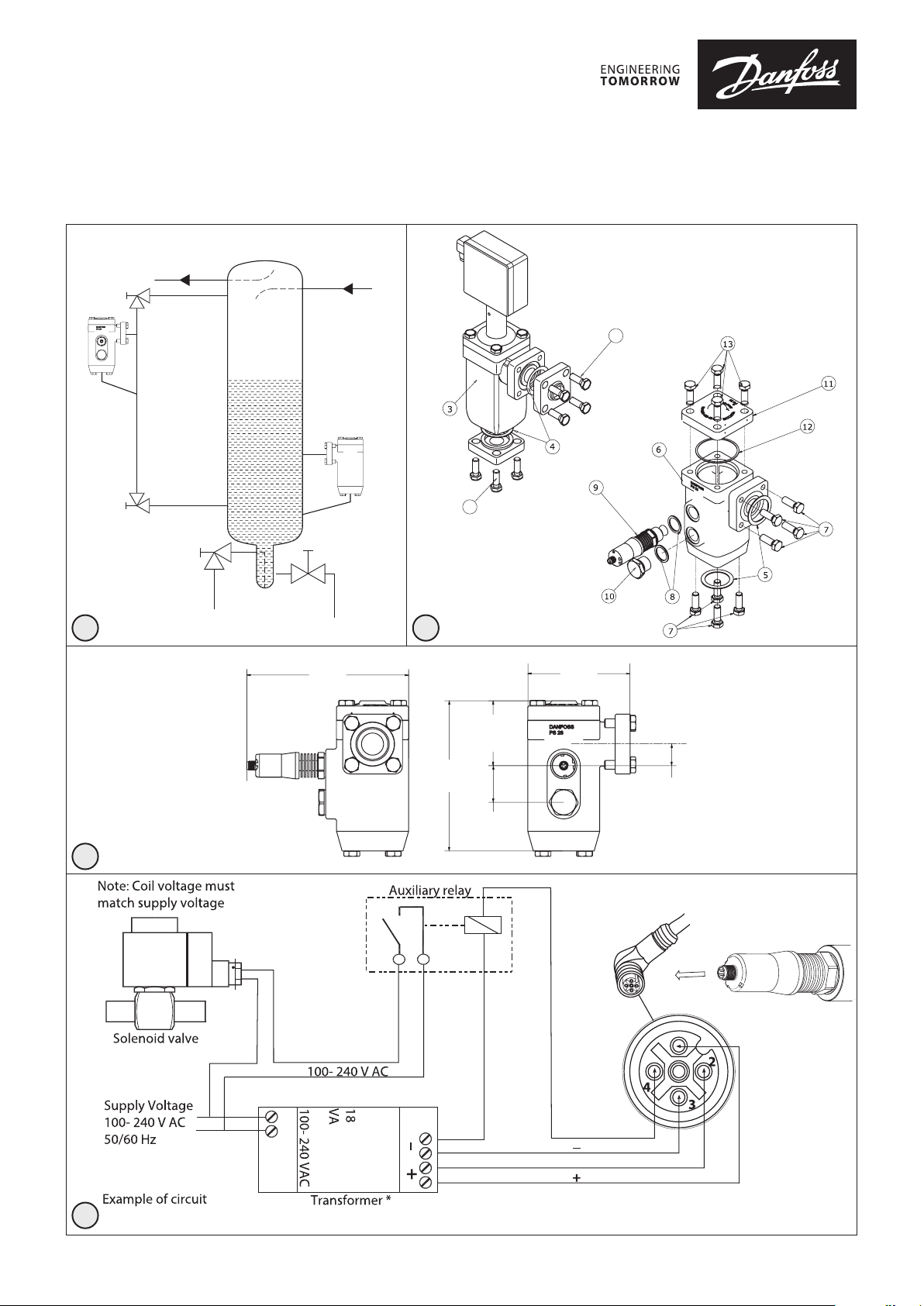
AKS 38 retrofit house is designed for a max.
working pressure of 28 bar (406 psig).
Electrical data (LLS 4000)
Power Supply: 24 V DC +/-25%, 80 mA
Standard power supply of type: SELV
(Separated Extra Low Voltage) with current
limit of max. 8 A.
Solid state relay: Max 30 V DC, 200 mA.
M12, 4 pin electrical connection.
Enclosure
AKS 38 Retrofit house: IP65
LLS 4000: IP66 /IP67
Liquid Level differential
The AKS 38 retrofit house is equipped
with 2 connections with 50 mm distance
(fig. 3), that can be used for mounting:
- 1 x LLS 4000 + plug (Hi/Lo level
control, default configuration)
- 2 x LLS 4000 (ON/OFF level control,
require additional LLS 4000)
For ON/OFF level control only, 1 x LLS 4000
can be used in combination with a time
delay via an externally managed time
delay.
The time delay shall be set with care
and provide an effective differential
NOT higher than 50 – 75 mm under
all conditions.
Installation
IMPORTANT
AKS 38 Retrofit house must
always be installed in a vertical
position (fig. 1 and 2).
AKS 38 is supplied with new bolts and
gaskets (fig. 2, pos. 5+7) for the retrofitting.
The external surfaces of the flanges must
be protected against corrosion with a suitable protective coat after installation.
To avoid an oil seal forming which would
affect the LLS 4000 measuring the bottom
connecting pipe must have an incline
towards the liquid separator.
Shut-off valves should be mounted as
close as possible to the retrofit house for
service (fig. 1).
Installing the retrofit house (fig. 2)
• Unscrew the 4 bolts on the side flange of
the existing AKS 38 (fig. 2, pos. 1)
• Unscrew the 4 bolts on the bottom flange
(fig. 2, pos. 2)
• Remove the old AKS 38 housing (fig. 2,
pos. 3) and scrap the old gaskets
(fig. 2, pos. 4)
• Install the new gaskets (fig. 2, pos. 5) and
position the retrofit housing (fig. 2, pos. 6)
to the flanges
• Fasten new 4 × M12×35 stainless steel
bolts (fig. 2, pos. 7) in each flange.
Tighten diagonally to a max. tightening
torque: 74 Nm (55 ft-lb)
Installing the LLS 4000 and ¾” plug (fig. 2)
• Install the 2 alu gaskets (fig. 2, pos. 8)
• Fasten the LLS 4000 (fig. 2, pos. 9) and ¾”
plug (fig. 2, pos. 10). Max. tightening
torque: 10 Nm/7.4 ft-lb pre-tightening
+ 45 degrees clockwise rotation
Max. tightening torque:
10 Nm/7.4 ft-lb pre-tightening +
45 degrees clockwise rotation.
Electrical installation (fig. 4)
The wiring diagram (fig. 4) is an example
and serves as an overall guide to the actual
installation.
24 V DC transformer for LLS 4000/4000U:
Danfoss code number 080Z0053,
AK-PS 075, or similar.
AK-PS 075 data:
Input Voltage
100 – 240 V AC
50 – 60 Hz
0.4 A (120 V AC) /
0.2 A (230 V AC)
Output Voltage:
24 V DC
0.75 A
18 VA
Observe:
Auxiliary relay:
Coil voltage: 24 V DC
Contact rating: Must match load of the
connected field coil (voltage and load)
The Auxiliary relay and the Transformer are
not included in the AKS 38 Retrofit kit.
Maintenance
IMPORTANT
The AKS 38 Retrofit housing
must be evacuated before
opening to air.
Replacing the flange gaskets
(fig. 2, pos. 5)
• Unscrew the 4 bolts on the side flange
(fig. 2, pos. 7)
• Unscrew the 4 bolts on the bottom
flange (fig. 2, pos. 7)
• Remove both gaskets (fig. 2, pos. 5)
• Install the new gaskets
• Fasten 4 bolts in each flange. Tighten
diagonally to a max. tightening torque:
74 Nm (55 ft-lb)
Replacing the top cover gasket
(fig. 2, pos. 12)
• Unscrew the 4 bolts (fig. 2, pos. 13)
• Remove the top cover (fig. 2, pos. 11)
• Remove the gasket (fig. 2, pos. 12)
• Install the new gasket
• Fasten 4 × bolts (fig. 2, pos. 13). Tighten
diagonally to a max. tightening torque:
74 Nm (55 ft-lb)
© Danfoss | DCS (ms) | 2021.04
AN375739676136en -000101 | 2
 Loading...